Page is loading ...

®
R O G R E SS
L IG H T IN G
P
R
P2538

Lifetime Limited Warranty
Progress Lighting fan motors are warranted to the END USER to be free of
electrical and/or mechanical defects for life. Pull chain switches, reverse
switches, capacitors and metal nishes are warranted for a period of 1
year. Warping of wooden or plastic blades is not covered by this warranty.
The END USER has the option of returning the defective fan to the place
of purchase during the rst 30 days for replacement. After 30 days, the
purchaser MUST contact Progress Lighting for repair or replacement.
The END USER also bears the responsibility for all costs in the removal,
shipping and reinstallation of fans or parts for repair or replacement.
Progress Lighting will not assume liability or responsibility for damages
(including incidental or consequential) caused by the improper installation
or operation of the unit or its component parts, or by the failure of
supporting hardware not supplied by Progress Lighting. This warranty
is given in lieu of all other guarantees, whether expressed or implied,
and is voided in cases of abuse, misuse or improper handling, negligence,
shipping damage, unauthorized repairs (made or attempted) or unusual
application.
Some states do not allow limitations on how long an implied warranty lasts
or the exclusion or limitations of incidental or consequential damages, so
the above limitations and exclusions may not apply to you. This warranty
gives you specic rights and you may have other rights which vary from
state to state.
Date Purchased
Store Purchased
UL Model No.
Serial No.
Vendor No.
UPC
52-TV
111017
Lifetime Limited Warranty

Safety Rules
Unpacking Your Fan
Installing Your Fan
Fan and Light Control Options
Operating Your Fan
Care of Your Fan
Troubleshooting
Specications
Table of Contents
1
2
3
6
10
11
11
12

1. To reduce the risk of electric shock, insure electricity
has been turned off at the circuit breaker or fuse box
before beginning.
2. All wiring must be in accordance with the National
Electrical Code ANSI/NFPA 70-1999 and local electrical codes.
Electrical installation should be performed by a
qualied licensed electrician.
3. CAUTION: To reduce the risk of personal injury, use only
the screws provided with the electrical box.
4. The outlet box and support structure must be securely
mounted and capable of reliably supporting 35 lbs. (15.9
kg). Use only UL Listed outlet boxes marked “Acceptable
for Fan Support of 35 lbs. (15.9 kg) or less.”
5. The fan must be mounted with a minimum of 7 feet
clearance from the trailing edge of the blades to the oor.
6. Do not operate reversing switch while fan blades are in
motion. Fan must be turned off and blades stopped before
reversing blade direction.
7. Avoid placing objects in path of the blades.
8. To avoid personal injury or damage to the fan and other
items, be cautious when working around or
cleaning the fan.
9. Do not use water or detergents when cleaning the fan or fan
blades. A dry dust cloth or lightly dampened cloth will be
suitable for most cleaning.
10. After making electrical connections, spliced conductors
should be turned upward and pushed carefully up into
electrical box. The wires should be spread apart with the
grounded conductor and the equipment-grounding
conductor on one side of the electrical box and ungrounded
conductor on the other side of the electrical box.
11. Electrical diagrams are for reference only. Light kits that
are not packed with the fan must be UL Listed and marked
suitable for use with the model fan you are installing.
Switches must be UL General Use Switches. Refer to the
instructions packaged with the light kits and switches for
proper assembly.
12. All set screws must be checked and retightened where
necessary before installation.
1. Safety Rules
READ AND SAVE THESE INSTRUCTIONS
TO REDUCE THE RISK OF FIRE, ELECTRIC SHOCK OR PERSONAL
INJURY, MOUNT TO OUTLET BOX MARKED “ACCEPTABLE FOR FAN
SUPPORT OF 35LBS. (15.9 KG) OR LESS”, AND USE SCREWS PRO-
VIDED WITH THE OUTLET BOX.
TO REDUCE THE RISK OF PERSONAL INJURY, DO NOT BEND THE
BLADE BRACKETS (ALSO REFERRED TO AS (“FLANGES”) DURING
ASSEMBLY OR AFTER INSTALLATION. DO NOT INSERT OBJECTS IN
THE PATH OF THE BLADES.

3
2
15
4
6
7
8
9
a. Blade attachment hardware
(9 Screws)
b. Electrical hardware & Balancing kit
(3 plastic wire connectors, blade
balancing kit)
5. Fan Motor Assembly
6. Blades (3)
7. Light Kit Fitter Assembly
8. Glass Shade
9. Light Bulbs (2)
1. Mounting Bracket (inside canopy)
2. 4.5” Ball/Downrod Assembly (hanger pin
and locking pin pre-attached)
3. Canopy with Canopy Ring (attached)
4. Decorative Motor Collar Cover
2. Unpacking Your Fan
Unpack your fan and check the contents. You should have the following items:
a
b

3. Installing Your Fan
Tools Required
Phillips screw driver or straight slotted screw
driver, adjustable wrench, step ladder, and
wire cutters.
Mounting Options
If there isn’t an existing electrical box, then
read the following instructions. Disconnect
the power by removing fuses or turning off
circuit breakers.
Secure the electrical box directly to the building
structure. Use appropriate fasteners and
building materials. The electrical box and
its support must be able to fully support the
moving weight of the fan (at least 35 lbs.).
Do not use plastic electrical boxes.
Figures 1, 2, and 3 are examples of different
ways to mount the electrical box.
Note: You may need a longer downrod to
maintain proper blade clearance when installing
on a steep, sloped ceiling. The maximum
angle allowable is 30˚. If the canopy touches
downrod, remove the decorative canopy
bottom cover and turn the canopy 180˚ before
attaching the canopy to the mounting plate.
To hang your fan where there is an existing
xture but no ceiling joist, you may need an
installation hanger bar as shown in Figure 4.
TO REDUCE THE RISK OF FIRE, ELECTRIC
SHOCK OR PERSONAL INJURY, MOUNT
TO OUTLET BOX MARKED “ACCEPTABLE
FOR FAN SUPPORT OF 35LBS. (15.9 KG) OR
LESS”, AND USE SCREWS PROVIDED WITH
THE OUTLET BOX. ELECTRICAL BOXES
COMMONLY USED FOR THE SUPPORT OF
LIGHTING FIXTURES MAY NOT BE ACCEPT-
ABLE FOR FAN SUPPORT AND MAY NEED TO
BE REPLACED. CONSULT A QUALIFIED ELEC-
TRICIAN IF IN DOUBT.
Figure 1
Figure 2
Figure 4
Figure 3

4.
Hanging the Fan
REMEMBER to turn off the power. Follow
the steps below to hang your fan properly.
NOTE: This fan is recommended for
standard ceiling mount using the downrod
provided with this fan. When using standard
ceiling installation with the 4.5 inch downrod
provided, the distance from the ceiling
to the bottom of the fan blades will be
approximately 12 inches.
Standard Ceiling Mounting
1. Remove the canopy ring from the canopy
by turning the ring to the right until it
unlocks. (Figure 5)
2. Remove the mounting plate from the
canopy by loosening the four screws on
the top of the canopy. Remove the two
non-slotted screws and loosen the slotted
screws. This will enable you to remove
the mounting plate. (Figure 6)
4. Remove the hanger pin and locking pin
from downrod assembly.
5. Route the wires exiting the top of the fan
motor through the decorative motor collar
cover then the canopy ring. Make sure the
slot openings are on top. Route the wires
through the canopy and then through the
ball/downrod assembly. (Figure 7)
Remove
Loosen but Do Not Remove
Turn Canopy Ring to Remove
Figure 5
Figure 6
6. Loosen, but do not remove, the set screws
on the collar on the top of the motor
housing.
7. Align the holes at the bottom of the
downrod with the holes in the collar on top
of the motor housing. (Figure 7)
Carefully insert the hanger pin through the
holes in the collar and downrod. Be careful
not to jam the hanger pin against the wiring
inside the downrod. Insert the locking pin
through the hole near the end of the bolt
until it snaps into its locked position, as
noted in the circle inset of Figure 7.
8. Re-tighten the set screws on the collar on
top of the motor housing.
9. Make sure the grommet is properly installed
in the collar cover, then slide the collar cover
on the downrod until it rests on the motor
housing. Be sure that the canopy and the
collar cover are both oriented correctly.
10. Proceed to “Installing the Fan” section.
FAILURE TO PROPERLY INSTALL SET SCREWS
AS NOTED IN STEP 8 COULD RESULT IN FAN
LOOSENING AND POSSIBLY FALLING.
Figure 7
Pin in
position
locked
Motor wires
Ball/Downrod
assembly
Canopy
Canopy
ring
cover
Motor collar
Tighten screws
Motor
collar
Hanger
pin
Locking
pin
Reverse
switch

Standard mounting
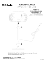
5.
Installing Fan to
the Electrical Box
WHEN MOUNTING THE FAN ON A SLOPED
CEILING, THE STANDARD BALL/DOWNROD
MOUNTING METHOD MUST BE USED. THE
MOUNTING PLATE MUST BE MOUNTED SO
THAT THE SLOT OPENINGS ARE ON THE
LOWER SIDE BY SLIDING THE MOUNTING
PLATE FROM THE TOP DOWN.
1. Pass the 120-volt supply wires through the
center hole in the ceiling mounting plate as
shown in Figure 8.
2. Install the ceiling mounting bracket on the
electrical box by using the mounting screws
provided with the electrical box. Note that
the at side of the mounting plate is toward
the electrical box. (Figure 8)
3. Tighten the two screws on the electrical box
securely.
4. Carefully lift the fan assembly up to the
ceiling mounting plate. Make sure the tab
on the mounting plate is properly seated in
the groove in the hanger ball. (Figure 9)
Figure 8
Washers
120V
Wires
UL Listed
Electrical
Box
Ceiling
Mounting
Bracket
Hook
Mounting
Screws
(Supplied with
Electiral Box)
WHEN USING THE STANDARD BALL/DOWNROD
MOUNTING, THE TAB IN THE RING AT THE
BOTTOM OF THE MOUNTING BRACKET MUST
REST IN THE GROOVE OF THE HANGER BALL.
FAILURE TO PROPERLY SEAT THE TAB IN THE
GROOVE COULD CAUSE DAMAGE TO WIRING.
Figure 9

6. Fan & Light Control Options
Selecting a Control
Your fan does not include controls for operating
the speed or lighting functions. Please select
a control that suits your preference from the
following guide.
(1) Remote Control Options
NON-DIMMABLE BULBS
When using bulbs that are not dimmable (such
as the included compact uorescent bulbs),
use Progress Lighting P2618-01 or equivalent
control.
DIMMABLE BULBS
When using bulbs that are dimmable (requires
separate purchase of LED or incandescent
bulbs), use Progress Lighting P2614-01 or
equivalent control.
(2) Hardwired Control Options
1-GANG SWITCH BOX
DIMMABLE BULBS
When using bulbs that are dimmable
(requires separate purchase of LED
or incandescent bulbs), use Progress
Lighting P2630-30 or equivalent control.
2-GANG SWITCH BOX
NON-DIMMABLE BULBS
When using bulbs that are not dimmable
(such as the included compact uorescent
bulbs), use Progress Lighting P2613-30
or equivalent control PLUS a separate
on/off control to operate lighting.
DIMMABLE BULBS
When using bulbs that are dimmable
(requires separate purchase of LED
or incandescent bulbs), use Progress
Lighting P2613-30 or equivalent control
PLUS a separate compatible dimmer
control to operate lighting.
A REMOTE CONTROL IS YOUR ONLY CONTROL
OPTION IF YOU ONLY HAVE 1 CIRCUIT
PROVIDING POWER TO THE FAN. THE REMOTE
RECEIVER WILL SPLIT THE CIRCUIT TO
PROVIDE SEPARATE CONTROL FOR THE FAN
SPEEDS AND LIGHTING.
HARDWIRED CONTROLS CAN ONLY BE USED
IF 2 CIRCUITS ARE PROVIDED TO POWER THE
FAN. ONE CIRCUIT WILL BE USED TO OPERATE
THE FAN SPEEDS AND ONE CIRCUIT WILL BE
USED TO OPERATE THE LIGHTING

7.
EACH WIRE NUT (WIRE CONNECTOR) SUPPLIED
WITH THIS FAN IS DESIGNED TO ACCEPT UP TO
ONE 12 GAUGE HOUSE WIRE AND TWO WIRES
FROM THIS FAN. IF YOU HAVE LARGER THAN
12 GAUGE HOUSE WIRING OR MORE THAN
ONE HOUSE WIRE TO CONNECT TO THE FAN
WIRING, CONSULT AN ELECTRICIAN FOR THE
PROPER SIZE WIRE NUTS TO USE.
USE THE PLASTIC WIRE CONNECTORS
SUPPLIED WITH YOUR FAN. SECURE THE
CONNECTORS WITH ELECTRICAL TAPE AND
ENSURE THERE ARE NO LOOSE STRANDS OR
CONNECTIONS.
BLUE
BLACK
WHITE
GREEN
BLUE
BLACK
WHITE
WHITE
Outlet
box
SUPPLY CIRCUIT
Green
BLACK
WHITE
Grounding to
Downrod
Figure 10
Making the Electrical
Connections
REMEMBER to disconnect the power. If
you feel you do not have enough electrical
wiring knowledge or experience, have your fan
installed by a licensed electrician.
Follow the steps below to connect the fan to
your household wiring. Use the wire
connecting nuts supplied with your fan and
supplied with remote control. Secure the
connectors with electrical tape. Make sure
there are no loose strands or
connections. (Figure 10)
1. Connect the two green fan ground wires,
located on the downrod and mounting
bracket, to the household ground wire.
2. Connect the neutral fan (White) wire to the
white neutral household wire.
3. Connect the fan supply (black and blue)
wire to the black household supply wire as
shown in gure 10.
4. After Connecting the wires, spread them
apart so that the green and white wires are
on one side of the outlet box and the black
wire is on the other side.
5. Turn the wire connecting nuts upward and
push the wiring into the outlet box.

Attaching the Fan
Blades
1. Insert the blade through the slot cut-off in
the center ywheel, align the three screw
holes in the blade with the screw holes in
the ywheel and secure with the screws
provided. (Figure 11)
2. Repeat for the remaining blades.
Figure 11
Figure 12
Blade Balancing
All blades are grouped by weight. Because
natural woods vary in density, the fan may
wobble even though the blades are weight
matched.
The following procedure should correct most
fan wobble. Check after each step.
1. Check that all blade screws are secure.
2. Most fan wobble problems are caused
when blade levels are unequal. Check this
level by selecting a point on the ceiling
above the tip of one of the blades. Measure
from a point on the center of each blade
to the point on the ceiling. Measure this
distance as shown in Figure 12. Rotate
the fan until the next blade is positioned
for measurement. Repeat for each blade.
Measurements deviation should be within
1/8”. Run the fan for 10 minutes.
Finishing the Fan
Installation
STANDARD CEILING MOUNTING
1. Align the locking slots of the ceiling
canopy with the two screws in the mounting
plate. Push up to engage the slots and turn
clockwise to lock in place. Immediately
tighten the two mounting screws rmly.
2. Install the remaining two mounting
screws into the holes in the canopy and
tighten rmly.
3. Install the decorative canopy ring by
aligning the ring’s slots with the screws
in the canopy. Rotate the ring counter-
clockwise to lock in place.
4. You may now proceed to attaching the
fan blades.
WHEN USING THE STANDARD BALL/DOWNROD
MOUNTING, THE TAB IN THE RING AT THE
BOTTOM OF THE MOUNTING PLATE MUST
REST IN THE GROOVE OF THE HANGER BALL.
FAILURE TO PROPERLY SEAT THE TAB IN THE
GROOVE COULD CAUSE DAMAGE TO WIRING.
3. Make sure that canopy is tightened securely
to ceiling mounting bracket and that the
ceiling mounting bracket is tightened
securely to the electrical box.
4. Interchanging two adjacent blades can
redistribute the weight and possibly result
in the smoother operation.
5. Use the enclosed Blade Balancing Kit if the
blade wobble is still noticeable.
8.

9.
Installing the Light
Kit/ Glass Bowl
CAUTION - To reduce the risk of electrical
shock, disconnect the electrical supply circuit
to the fan before installing the light kit.
THE GLASS IS FRAGILE, USE CARE
WHEN INSTALLING THE LIGHT KIT AND
THE GLASS SHADE.
1. Loosen but do not remove three of four
mounting screws from the light kit adaptor
below the fan motor assembly; remove one
mounting screw. (Figure 13)
2. Connect the blue and white wires exiting
the light kit adaptor with the black and
white wires from the light kit assembly by
engaging the molded adaptor plugs (blue to
black; white to white).
3. Carefully tuck connectors into the light
kit adaptor. Position the light kit assembly
onto the light kit adaptor, aligning each of
the four holes. Rotate the light kit assembly
clockwise to engage the three mounting
screws with the three key hole slots, tighten
the screws. Re-install the one mounting
screw that was removed in step 1 and
tighten rmly.
4. With power off, install the two uorescent
bulbs (Max. 13W or equivalent LED or
incandescent bulbs) by screwing into the
light bulb sockets. (Figure 14)
5. Place the glass shade into the light kit
assembly, aligning the three at areas
on the top ange of the glass shade with
the three raised dimples in the light kit
assembly. Turn the glass shade clockwise
until it stops. (Figure 14)
Glass
Light Kit
Assembly
Bulbs(2)
(Provided)
Dimples
Raised
Flat Area
Figure 13
Figure 14
PERIODICALLY CHECK THE GLASS IS
SEATED FULLY CLOCKWISE IN THE LIGHT KIT
ASSEMBLY.
ALLOW THE BULB TO COOL COMPLETELY
BEFORE TOUCHING OR REPLACING THE
BULBS TO AVOID ACCIDENTAL BURNING OF
THE SKIN.

10. Operating Your Fan
Speed settings for warm or cool weather depend
on factors such as room size, ceiling height,
number of fans, and so on.
The fan shipped from the factory with the
reversing switch positioned to circulate air
downward. If airow is desired in the opposite
direction, turn your fan off and wait for the
blades to stop turning, then slide the reversing
switch (located at the top of the motor housing,
refer to gure 7 on page 4) to opposite position,
and turn fan on again. The fan blades will turn
in the opposite direction and reverse airow.
Figure 15
Figure 16
Warm weather - (Forward) A downward air
ow creates a cooling effect as shown in Figure
15. This allows you to set your air conditioner
on a higher setting without affecting your
comfort.
Cool weather - (Reverse) An upward air ow
moves warm air off the ceiling are as shown in
Figure 16. This allows you to set your heating
unit on a lower setting without affecting your
comfort.

11. Care of Your Fan and Troubleshooting
Care of Your Fan
Here are some suggestions to help you
maintain your fan.
1. Because of the fan’s natural movement,
some connections may become loose.
Check the support connections, brackets,
and blade attachments twice a year. Make
sure they are secure. (It is not necessary to
remove fan from ceiling.)
2. Clean your fan periodically to help maintain
its new appearance over the years. Do not
use water when cleaning, this could damage
the motor, or the wood or possibly cause
an electrical shock. Use only a soft brush
or lint-free cloth to avoid scratching the
nish. The plating is sealed with a lacquer
to minimize discoloration or tarnishing.
Warning - Make sure the power is off
before cleaning your fan.
3. You can apply a light coat of furniture polish
to the wood for additional protection and
enhanced beauty. Cover small scratches
with a light application of shoe polish.
4. There is no need to oil your fan.
The motor has permanently lubricated
sealed ball bearings.
MAKE SURE THE POWER IS OFF AT THE ELECTRICAL PANEL BOX
BEFORE YOU ATTEMPT TO MAKE ANY REPAIRS. REFER TO THE SECTION,
“MAKING ELECTRICAL CONNECTIONS.”
Fan will not start
Fan sounds noisy
1. Check main and branch circuit fuses or breakers
2. Check line wire connections to the fan and switch wire connections in
the switch housing. CAUTION: Make sure main power is off.
3. Check batteries in the transmitter. Does the red LED light come on?
Are you standing close enough to the fan? (Normal range is 10-20
feet.) Are the dip switch settings the same on the transmitter (hand unit)
and receiver? REMEMBER TO TURN OFF POWER SUPPLY
BEFORE CHECKING THE DIP SWITCH SETTINGS IN
RECEIVER.
1. Make sure all motor housing screws are snug.
2. Make sure the screws that attach the fan blade bracket to the motor hub
are tight.
3. Make sure wire nut connections are not rattling against each other or
the interior wall of the switch housing.
CAUTION: Make sure power is off.
4. Allow a 24-hour “breaking in” period. Most noises associated with a
new fan disappear during this time.
5. If using the Ceiling Fan light kit, make sure the screws securing the
glassware are tight. Check that the light bulb is also secure.
6. Make sure the canopy is a short distance from the ceiling.
It should not touch the ceiling.
7. Make sure your electrical box is secure and rubber isolator pads were
used between the mounting bracket and electrical box.
Troubleshooting
Problem Solution

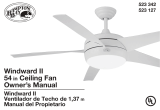
12. Specications
FAN
SIZE
SPEED VOLTS
FAN POWER
CONSUMPTION
(WITHOUT LIGHTS)
WATTS
AIRFLOW
CFM
AIRFLOW
EFFICIENCY
(HIGHER IS BETTER)
CFM/WATT
NET
WEIGHT
GROSS
WEIGHT
CUBE
FEET
52”
Low 120 11 1425 130
18.07
Lbs
20.72
Lbs
1.7
Med 120 31 3132 101
High 120 64 4742 79
©2016 Progress Lighting, Inc.
701 Millennium Blvd.,
Greenville, SC 29607
All Rights Reserved

Montaje estándar
5.
Cómo instalar el ventilador
en la caja eléctrica
AL INSTALAR EL VENTILADOR EN UN TECHO
INCLINADO, TIENES QUE HACERLO POR EL
MÉTODO DE MONTAJE CON TUBO BAJANTE
Y BOLA ESTÁNDAR. LA PLACA DE MONTAJE TIENE
QUE INSTALARSE DE MANERA TAL QUE LAS
ABERTURAS DE RANURA QUEDEN SOBRE EL LADO
INFERIOR, DESLIZANDO LA PLACA DE MONTAJE
DESDE LA PARTE SUPERIOR HACIA ABAJO.
1. Pasa los cables de suministro de 120 V a través
del oricio central de la placa de montaje del
techo, como se muestra en la Figura 8.
2. Instala el soporte de montaje de techo sobre
la caja eléctrica, con los tornillos de montaje
incluidos. Fíjate que el lado plano de la
placa de montaje esté orientado hacia la caja
eléctrica. (Figura 8)
3. Aprieta bien los dos tornillos en la caja
eléctrica.
4. Con cuidado alza el conjunto del ventilador
hasta la placa de montaje en el techo.
Asegúrate de que la pestaña sobre la placa de
montaje encaje bien en la ranura de la bola de
soporte. (Figura 9)
Figura 8
Arandelas
Cables de 120 V
Caja
eléctrica
aprobada
por UL
Soporte
de montaje
en techo
Gancho
Tornillos de montaje
(incluidos con
la caja eléctrica)
EN EL MONTAJE ESTÁNDAR DE TUBO BAJANTE
Y BOLA, LA PESTAÑA EN EL ARO DE LA PARTE
INFERIOR DEL SOPORTE DE MONTAJE TIENE
QUE ENCAJAR EN LA RANURA DE LA BOLA DE
SOPORTE. NO ENCAJAR BIEN LA LENGÜETA EN
LA RANURA PUDIERA DAÑAR EL CABLEADO.
Figura 9
ADVERTENCIA
PRECAUCIÓN

7.
CADA TUERCA DEL CABLE (CONECTOR DE
CABLE) INCLUIDA CON ESTE VENTILADOR
ESTÁ DISEÑADA PARA ACEPTAR UN CABLE
DOMÉSTICO DE CALIBRE 12 COMO MÁXIMO Y
DOS CABLES DEL VENTILADOR. SI TIENES UN
CABLEADO DOMÉSTICO DE MAYOR CALIBRE
QUE 12 O MÁS DE UN CABLE DOMÉSTICO PARA
CONECTAR AL CABLEADO DEL VENTILADOR,
CONSULTA A UN ELECTRICISTA SOBRE EL
TAMAÑO ADECUADO DE LAS TUERCAS DE
CABLE A USAR.
USA LOS CONECTORES DE CABLES PLÁSTICOS
INCLUIDOS CON TU VENTILADOR. SUJETA LOS
CONECTORES CON CINTA DE ELECTRICISTA Y
ASEGÚRATE DE QUE NO HAYA CONEXIONES NI
CABLES SUELTOS.
AZUL
NEGRO
BLANCO
VERDE
AZUL
NEGRO
BLANCO
BLANCO
Caja eléctrica
CIRCUITO DE SUMINISTRO
Verde
NEGRO
BLANCO
Conexión a tierra
al tubo bajante
Figura 10
Cómo hacer las
conexiones eléctricas
RECUERDA cortar la electricidad. Si crees
que no tienes suciente experiencia o
conocimientos en cableado eléctrico, contrata
a un electricista con licencia para que instale
el ventilador.
Sigue estos pasos para conectar tu ventilador
al circuito de tu hogar. Usa las tuercas de
conexión de cable incluidas con el ventilador
y el control remoto. Asegura los conectores
con cinta aislante. Asegúrate de que no haya
conexiones ni cables sueltos. (Figura 10)
1. Conecta los dos cables verdes de conexión
a tierra del ventilador, ubicados en el tubo
bajante y el soporte de montaje, al cable de
conexión a tierra del hogar.
2. Conecta el cable neutro (blanco) del
ventilador al cable neutro blanco del
circuito eléctrico del hogar.
3. Conecta el cable de alimentación (negro y
azul) del ventilador al cable de suministro
negro del hogar como se muestra en la
Figura 10.
4. Después de conectar los cables, sepáralos
de manera que los cables verde y blanco
queden a un lado de la caja eléctrica y el
cable negro, al otro.
5. Gira las tuercas de conexión del cable hacia
arriba y coloca el cableado dentro de la caja
eléctrica.
NOTA
ADVERTENCIA

12. Especicaciones
TAMAÑO DEL
VENTILADOR
VELOCIDAD VOLTIOS
CONSUMO DE
ENERGÍA DEL
VENTILADOR
(SIN LUCES)
WATTS
FLUJO DE
AIRE
CFM
LA EFICIENCIA
DEL FLUJO DE
AIRE
(MÁS ALTO ES
MEJOR)
CFM/WATT
PESO
NETO
PESO
BRUTO
PIES
CÚBICOS
1.3 m
Baja 120 11 1425 130
8.2
Kg
9.4
Kg
1.7
Media 120 31 3132 101
Alta 120 64 4742 79
©2016 Progress Lighting, Inc.
701 Millennium Blvd.,
Greenville, SC 29607
Todos los derechos reservados
/