Page is loading ...

®
P250080
93157631_A

Date Purchased
Store Purchased
Model No.
Serial No.
Vendor No.
UPC
30-Year Limited Warranty
111017
Progress Lighting fan motors are warranted to the END USER to be free of electrical
and/or mechanical defects for a period of 30 (thirty) years from date of sale. Pull chain
switches, reverse switches, capacitors and metal nishes are warranted for a period of 1
year. Warping of wooden or plastic blades is not covered by this warranty.
The END USER has the option of returning the defective fan to the place of purchase during
the rst 30 days for a replacement. After 30 days, the purchaser MUST contact Progress
Lighting for repair or replacement. The END USER also bears the responsibility for all
costs in the removal, shipping and reinstallation of fans or parts for repair or replacement.
Progress Lighting will not assume liability or responsibility for damages (including
incidental or consequential) caused by improper installation or operation of the unit or
its component parts, or by the failure of supporting hardware not supplied by Progress
Lighting. This warranty is given in lieu of all other guarantees, whether expressed or
implied, and is voided in cases of abuse, misuse or improper handling, negligence,
shipping damage, unauthorized repairs (made or attempted) or unusual application.
Some states do not allow limitations on how long an implied warranty lasts or the
exclusion or limitations of incidental or consequential damages, so the above limitations
and exclusions may not apply to you. This warranty gives you specic rights and you may
have other rights which vary from state to state.
P250080
785247264261
785247264285
785247264292
785247264308
785247264315
785247264278

1
2
3
8
9
9
10
Safety Rules
Unpacking Your Fan
Installing Your Fan
Operating Your Fan
Care of Your Fan
Troubleshooting
Specications
Table of Contents

1. To reduce the risk of electric shock, ensure electricity
has been turned off at the circuit breaker or fuse box
before beginning.
2. All wiring must be in accordance with the National
Electrical Code ANSI/NFPA 70-1999 and local electrical codes.
Electrical installation should be performed by a
qualied licensed electrician.
3. CAUTION: To reduce the risk of personal injury, use only
the screws provided with the electrical box.
4. The outlet box and support structure must be securely
mounted and capable of reliably supporting 35 lbs. (15.9
kg). Use only UL Listed outlet boxes marked “Acceptable
for Fan Support of 35 lbs. (15.9 kg) or less.”
5. The fan must be mounted with a minimum of 7 feet
clearance from the trailing edge of the blades to the oor.
6. Do not operate reversing switch while fan blades are in
motion. Fan must be turned off and blades stopped before
reversing blade direction.
7. Avoid placing objects in path of the blades.
8. To avoid personal injury or damage to the fan and other
items, be cautious when working around or
cleaning the fan.
9. Do not use water or detergents when cleaning the fan or fan
blades. A dry dust cloth or lightly dampened cloth will be
suitable for most cleaning.
10. After making electrical connections, spliced conductors
should be turned upward and pushed carefully up into
electrical box. The wires should be spread apart with the
grounded conductor and the equipment-grounding
conductor on one side of the electrical box and ungrounded
conductor on the other side of the electrical box.
11. Electrical diagrams are for reference only. Light kits that
are not packed with the fan must be UL Listed and marked
suitable for use with the model fan you are installing.
Switches must be UL General Use Switches. Refer to the
instructions packaged with the light kits and switches for
proper assembly.
12. All set screws must be checked and retightened where
necessary before installation.
1. Safety Rules
READ AND SAVE THESE INSTRUCTIONS
TO REDUCE THE RISK OF FIRE, ELECTRIC SHOCK OR PERSONAL
INJURY, MOUNT TO OUTLET BOX MARKED “ACCEPTABLE FOR FAN
SUPPORT OF 35LBS. (15.9 KG) OR LESS”, AND USE SCREWS PRO-
VIDED WITH THE OUTLET BOX.
TO REDUCE THE RISK OF PERSONAL INJURY, DO NOT BEND THE
BLADE BRACKETS (ALSO REFERRED TO AS (“FLANGES”) DURING
ASSEMBLY OR AFTER INSTALLATION. DO NOT INSERT OBJECTS IN
THE PATH OF THE BLADES.
TO REDUCE THE RISK OF SHOCK, THIS FAN MUST BE INSTALLED
WITH AN ISOLATION WALL CONTROL/SWITCH.

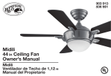
a. Mounting hardware
(16 blade attachment screws)
b. Electrical hardware & Balancing
kit (3 plastic wire connectors, blade
balancing kit)
c. Pull chain
d. Extra blade bracket screw
4. Blade Arms (5)
5. Fan Motor Assembly
6. Blades (5)
1. Mounting Bracket (inside canopy)
2. 4.25” Ball/Downrod Assembly (hanger pin
and locking pin pre-attached)
3. Canopy
2. Unpacking Your Fan
Unpack your fan and check the contents. You should have the following items:
5
1
2
3
4
6
a
b
c d

3. Installing Your Fan
Tools Required
Phillips screw driver or straight slotted screw
driver, adjustable wrench, step ladder, and
wire cutters.
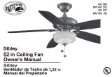
Mounting Options
If there isn’t an existing electrical box, then
read the following instructions. Disconnect
the power by removing fuses or turning off
circuit breakers.
Secure the electrical box directly to the building
structure. Use appropriate fasteners and
building materials. The electrical box and
its support must be able to fully support the
moving weight of the fan (at least 35 lbs.).
Do not use plastic electrical boxes.
Figures 1, 2, and 3 are examples of different
ways to mount the electrical box.
Note: You may need a longer downrod to
maintain proper blade clearance when
installing on a steep, sloped ceiling. The
maximum angle allowable is 30˚. If the
canopy touches downrod, remove the
decorative canopy bottom cover and turn
the canopy 180˚ before attaching the canopy
to the mounting bracket.
To hang your fan where there is an existing
xture but no ceiling joist, you may need an
installation hanger bar as shown in Figure 4.
TO REDUCE THE RISK OF FIRE, ELECTRIC
SHOCK OR PERSONAL INJURY, MOUNT
TO OUTLET BOX MARKED “ACCEPTABLE
FOR FAN SUPPORT OF 35LBS. (15.9 KG) OR
LESS”, AND USE SCREWS PROVIDED WITH
THE OUTLET BOX. ELECTRICAL BOXES
COMMONLY USED FOR THE SUPPORT OF
LIGHTING FIXTURES MAY NOT BE ACCEPT-
ABLE FOR FAN SUPPORT AND MAY NEED TO
BE REPLACED. CONSULT A QUALIFIED ELEC-
TRICIAN IF IN DOUBT.
Figure 1
Figure 2
Figure 4
Figure 3

4.
Hanging the Fan
REMEMBER to turn off the power. Follow
the steps below to hang your fan properly.
NOTE: This fan is recommended for
standard ceiling mount using the downrod
provided with this fan. When using standard
ceiling installation with the 4.25 inch
downrod provided, the distance from the
ceiling to the bottom of the fan blades will be
approximately 10.4 inches.
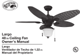
Standard Ceiling Mounting
1. Remove the mounting bracket from the
canopy by loosening the four screws on
the top of the canopy. Remove the two
non-slotted screws and loosen the slotted
screws. This will enable you to remove the
mounting bracket. (Figure 5)
2. Remove the hanger pin and locking pin from
downrod assembly.
3. Make sure the slot openings are on top.
Route the wires through the canopy and then
through the ball/downrod assembly. (Figure
6)
4. Loosen, but do not remove, the set screws
on the collar on the top of the motor
housing.
Figure 6
5. Align the holes at the bottom of the downrod
with the holes in the collar on top of the
motor housing. (Figure 6)
Carefully insert the hanger pin through the
holes in the collar and downrod. Be careful
not to jam the hanger pin against the wiring
inside the downrod. Insert the locking pin
through the hole near the end of the bolt until
it snaps into its locked position, as noted in
the circle inset of Figure 6.
6. Re-tighten the set screws on the collar on top
of the motor housing.
7. Make sure that the canopy is oriented
correctly.
8. Proceed to “Installing the Fan” section.
FAILURE TO PROPERLY INSTALL SET SCREWS
AS NOTED IN STEP 6 COULD RESULT IN FAN
LOOSENING AND POSSIBLY FALLING.
Slot opening
Motor wires
Locking Pin
Tighten
screws
Hanger Pin
Canopy
Ball/Downrod
assembly
Pin in locked
position
Motor
Collar
Remove
Loosen but Do Not Remove
Figure 5

Standard Mounting
5.
Installing Fan to
the Electrical Box
WHEN MOUNTING THE FAN ON A SLOPED
CEILING, THE STANDARD BALL/DOWNROD
MOUNTING METHOD MUST BE USED. THE
MOUNTING BRACKET MUST BE MOUNTED
SO THAT THE SLOT OPENINGS ARE ON THE
LOWER SIDE BY SLIDING THE MOUNTING
BRACKET FROM THE TOP DOWN.
1. Pass the 120-volt supply wires through the
center hole in the ceiling mounting bracket
as shown in Figure 7.
2. Install the ceiling mounting bracket on the
electrical box by using the mounting screws
provided with the electrical box. Note that
the at side of the mounting bracket is
toward the electrical box. (Figure 7)
3. Tighten the two screws on the electrical box
securely.
4. Carefully lift the fan assembly up to the
ceiling mounting bracket. Make sure the tab
on the mounting bracket is properly seated
in the groove in the hanger ball. (Figure 8)
Figure 7
Washers
120V
Wires
UL Listed
Electrical
Box
Ceiling
Mounting
Bracket
Hook
Mounting
Screws
(Supplied with
Electrical Box)
Slot opening
WHEN USING THE STANDARD BALL/DOWNROD
MOUNTING, THE TAB IN THE RING AT THE
BOTTOM OF THE MOUNTING BRACKET MUST
REST IN THE GROOVE OF THE HANGER BALL.
FAILURE TO PROPERLY SEAT THE TAB IN THE
GROOVE COULD CAUSE DAMAGE TO WIRING.
Figure 8

6.
EACH WIRE NUT (WIRE CONNECTOR) SUPPLIED
WITH THIS FAN IS DESIGNED TO ACCEPT UP TO
ONE 12 GAUGE HOUSE WIRE AND TWO WIRES
FROM THIS FAN. IF YOU HAVE LARGER THAN
12 GAUGE HOUSE WIRING OR MORE THAN
ONE HOUSE WIRE TO CONNECT TO THE FAN
WIRING, CONSULT AN ELECTRICIAN FOR THE
PROPER SIZE WIRE NUTS TO USE.
USE THE WIRE CONNECTORS SUPPLIED WITH
YOUR FAN. SECURE THE CONNECTORS WITH
ELECTRICAL TAPE AND ENSURE THERE ARE
NO LOOSE STRANDS OR CONNECTIONS
Figure 9
Making the Electrical
Connections
REMEMBER to disconnect the power. If
you feel you do not have enough electrical
wiring knowledge or experience, have your fan
installed by a licensed electrician.
Follow the steps below to connect the fan to
your household wiring. Use the wire
connecting nuts supplied with your fan. Secure
the connectors with electrical tape. Make sure
there are no loose strands or
connections. (Figure 9)
1. Connect the two green fan ground wires,
located on the downrod and mounting
bracket, to the household ground wire.
2. Connect the neutral fan (white) wire to the
white neutral household wire.
3. Connect the fan supply (black and blue) wire
to the black household supply wire as shown
in gure 9.
4. After connecting the wires, spread them apart
so that the green and white wires are on one
side of the outlet box and the black wire is on
the other side.
5. Turn the wire connecting nuts upward and
push the wiring into the outlet box.
SUPPLY CIRCUIT
BLACK
WHITE
WHITE
BLUE
BLACK
WHITE
BLACK
WHITE
BLUE
GREEN
Grounding
to Downrod
Outlet
box
Fan is wired to accept a
universal light kit (not included)

Attaching the Fan
Blades
NOTE: Your fan blades are reversible. Select the
blade nish which best accentuates your decor.
1. Attach blade to blade bracket using screws shown
in Figure 10. Repeat for the two remaining screws.
2. Tighten each screw securely.
Figure 11
Finishing the Fan
Installation
STANDARD CEILING MOUNTING
1. Align the locking slots of the ceiling canopy with
the two screws in the mounting bracket. Push up
to engage the slots and turn clockwise to lock
in place. Immediately tighten the two mounting
screws rmly.
2. Install the remaining two mounting screws into
the holes in the canopy and tighten rmly.
3. You may now proceed to attaching the fan blades.
WHEN USING THE STANDARD BALL/DOWNROD
MOUNTING, THE TAB IN THE RING AT THE
BOTTOM OF THE MOUNTING PLATE MUST
REST IN THE GROOVE OF THE HANGER BALL.
FAILURE TO PROPERLY SEAT THE TAB IN THE
GROOVE COULD CAUSE DAMAGE TO WIRING.
7.
Figure 10
Blade Balancing
All blades are grouped by weight. Because natural
woods vary in density, the fan may wobble even
though the blades are weight matched.
The following procedure should correct most fan
wobble. Check after each step.
1. Check that all blade screws are secure.
2. Most fan wobble problems are caused when blade
levels are unequal. Check this level by selecting
a point on the ceiling above the tip of one of the
blades. Measure from a point on the center of
each blade to the point on the ceiling. Measure
this distance as shown in Figure 12. Rotate the fan
until the next blade is positioned for measurement.
Repeat for each blade. Measurements deviation
should be within 1/8”. Run the fan for 10 minutes.
3. Make sure that canopy is tightened securely to
ceiling mounting bracket and that the ceiling
mounting bracket is tightened securely to the
electrical box.
4. Interchanging two adjacent blades can redistribute
the weight and possibly result in the smoother
operation.
5. Use the enclosed Blade Balancing Kit if the blade
wobble is still noticeable.
3. Fasten the blade assembly to the motor by aligning
the screw holes on the bottom of the fan motor
with the holes on the blade arm, and tightening the
motor screws. Please note that the motor screws
are preattached into the blade brackets. (Figure 11)
4. Repeat steps 1,2 & 3 for the remaining blades.
Figure 12
Blade
Blade Arm Screws
Screws
Blade Arm

8. Operating Your Fan
Speed settings for warm or cool weather
depend on factors such as room size, ceiling
height, number of fans, and so on.
The fan shipped from the factory with the
reverse switch positioned to circulate air
downward. If airow is desired in the opposite
direction, turn your fan off and wait for the
blades to stop turning, then slide the reverse
switch (located on the switch housing, refer to
gure 13) to opposite position, and turn fan on
again. The fan blades will turn in the opposite
direction and reverse airow. Figure 14
Figure 15
Warm weather - (Forward) A downward
air ow creates a cooling effect as shown
in Figure 14. This allows you to set your
air conditioner on a higher setting without
affecting your comfort.
Cool weather - (Reverse) An upward air ow
moves warm air off the ceiling are as shown in
Figure 15. This allows you to set your heating
unit on a lower setting without affecting your
comfort.
Install Pull Chain
Install the pull chain extension chain and fob
(Figure 13).
Figure 13
Fob
Reverse
switch

9. Care of Your Fan and Troubleshooting
Care of Your Fan
Here are some suggestions to help you
maintain your fan.
1. Because of the fan’s natural movement,
some connections may become loose.
Check the support connections, brackets,
and blade attachments twice a year. Make
sure they are secure. (It is not necessary to
remove fan from ceiling.)
2. Clean your fan periodically to help maintain
its new appearance over the years. Do not
use water when cleaning, this could damage
the motor, or the wood or possibly cause
an electrical shock. Use only a soft brush
or lint-free cloth to avoid scratching the
nish. The plating is sealed with a lacquer to
minimize discoloration or tarnishing.
Warning - Make sure the power is off
before cleaning your fan.
3. You can apply a light coat of furniture polish
to the wood for additional protection and
enhanced beauty. Cover small scratches with
a light application of shoe polish.
4. There is no need to oil your fan.
The motor has permanently lubricated sealed
ball bearings.
MAKE SURE THE POWER IS OFF AT THE ELECTRICAL PANEL BOX
BEFORE YOU ATTEMPT TO MAKE ANY REPAIRS. REFER TO THE SECTION,
“MAKING ELECTRICAL CONNECTIONS.”
Fan will not start
Fan sounds noisy
1. Check main and branch circuit fuses or breakers
2. Check line wire connections to the fan and switch wire connections in
the switch housing. CAUTION: Make sure main power is off.
1. Make sure all motor housing screws are snug.
2. Make sure the screws that attach the fan blade bracket to the motor hub
are tight.
3. Make sure wire nut connections are not rattling against each other or
the interior wall of the switch housing.
CAUTION: Make sure power is off.
4. Allow a 24-hour “breaking in” period. Most noises associated with a
new fan disappear during this time.
5. If using the Ceiling Fan light kit, make sure the screws securing the
glassware are tight. Check that the light bulb is also secure.
6. Make sure the canopy is a short distance from the ceiling.
It should not touch the ceiling.
7. Make sure your electrical box is secure and rubber isolator pads were
used between the mounting bracket and electrical box.
Troubleshooting
Problem Solution

10. Specications
FAN
SIZE SPEED VOLTS
FAN POWER
CONSUMPTION
(WITHOUT LIGHTS)
WATTS
AIRFLOW
CFM
AIRFLOW
EFFICIENCY
(HIGHER IS BETTER)
CFM/WATT
NET
WEIGHT
GROSS
WEIGHT
CUBE
FEET
52” Low 120 10.58 1898 179.4 13.89
Lbs
15.43
Lbs 1.3
High 120 58.26 4591 78.8
©2016 Progress Lighting, Inc.
701 Millennium Blvd.,
Greenville, SC 29607
All Rights Reserved

®
Manual de instalación de ventilador de techo
P250080
93157631_A

30 años de garantía limitada
111017
Los motores de ventilador Progress Lighting están garantizados al USUARIO FINAL
por treinta (30) años, a partir de la fecha de compra, de que estarán libres de defectos
eléctricos y/o mecánicos. Los interruptores activados por cadena, interruptores de reversa,
capacitores y acabados de metal tienen 1 año de garantía. No están cubiertas por esta
garantía las deformaciones de las aspas de madera o plástico.
El USUARIO FINAL tiene la opción de devolver el ventilador defectuoso adonde lo
compró, dentro de los 30 días siguientes a la compra, al efecto de su reposición. Pasados
esos 30 días, el comprador TIENE que contactar a Progress Lighting para reparación o
reposición. El USUARIO FINAL es responsable de todos los costos por desmontaje,
envío y reinstalación del ventilador, así como de las partes y piezas a reparar o reponer.
Progress Lighting no asumirá responsabilidad alguna por daños (incluso incidentales
o consecuentes) causados por instalación o manipulación inapropiadas de la unidad
o sus partes y piezas componentes, ni por fallas de herrajes de soporte que no fueron
suministrados por Progress Lighting. Esta garantía se concede en sustitución de todas las
demás, ya sean explícitas o implícitas, y se anulará en caso de uso abusivo o aplicación
inusual, mal uso o mala manipulación, negligencia, daños en el envío y reparaciones no
autorizadas (consumadas o intentadas).
Algunos estados no permiten limitaciones en la duración de una garantía implícita ni
exclusión ni limitaciones de daños incidentales o consecuentes, así que las exclusiones o
limitaciones referidas más arriba pudieran no aplicarse a su caso. Esta garantía le otorga
derechos especícos y es posible que usted tenga otros, que varían de estado a estado.
P250080
Fecha de compra
Modelo núm.
Número de serie
Proveedor Nº.
UPC
Tienda donde
se compró
785247264261
785247264285
785247264292
785247264308
785247264315
785247264278

1
2
3
8
9
9
10
Normas de seguridad
Cómo desempacar el ventilador
Cómo instalar el ventilador
Cómo usar el ventilador
Cuidado del ventilador
Solución de problemas
Especicaciones
Tabla de contenido

1. Para disminuir el riesgo de descarga eléctrica, antes de comenzar
la instalación asegúrate de que la electricidad ha sido cortada en
el cortacircuitos o en la caja de fusibles.
2. Todo el cableado tiene que cumplir con el Código Nacional
de Electricidad ANSI/NFPA 70-1999 y los códigos eléctricos
locales. La instalación eléctrica debe hacerse por un electricista
calicado con licencia.
3. PRECAUCIÓN: Para reducir el riesgo de lesiones físicas, usa
sólo los tornillos suministrados con la caja de distribución.
4. La caja eléctrica y estructura de soporte tienen que montarse de
forma segura para poder sostener con conanza 35 lb. (15.9 kg).
Usa solo cajas eléctricas aprobadas por UL y marcadas como
“Apropiadas para sostener ventiladores de 35 lb (15.9 kg) o
menos”.
5. El ventilador tiene que montarse con al menos 7 pies (2.13 m) de
separación entre el borde trasero de las aspas y el piso.
6. No operes el interruptor de reversa mientras las aspas del ventilador
estén en movimiento. El ventilador tiene que estar apagado y las
aspas detenidas antes de invertir el sentido del movimiento.
7. Evita colocar objetos en la trayectoria de las aspas.
8. Para evitar lesiones personales o daños al ventilador y otros
artículos, ten cuidado al limpiarlo o al trabajar cerca de él.
9. No usar agua ni detergentes para limpiar el ventilador o las
aspas. Para limpiar, casi siempre será adecuado un paño seco o
ligeramente humedecido con que quitar el polvo.
10. Después de concluir con las conexiones eléctricas, debes voltear
los conductores empalmados hacia arriba y empujarlos con cuidado
hacia dentro de la caja de distribución. Los cables deben estar
separados, con el cable y el conductor a tierra del equipo hacia uno
de los lados de la caja eléctrica y el conductor sin conexión a tierra
hacia el lado opuesto.
11. Los diagramas eléctricos son sólo para referencia. Los kits de luces
no empaquetados con el ventilador tienen que estar aprobados
por UL y marcados como apropiados para usar con el modelo de
ventilador que estás instalando. Los interruptores tienen que estar
clasicados de uso general por UL. Para ensamblar bien, consulta
las instrucciones adjuntas a los kits de luces e interruptores.
12. Antes de la instalación, todos los tornillos de jación tienen que
comprobarse y reajustarse donde sea necesario.
1. Normas de seguridad
LEE Y GUARDA ESTAS INSTRUCCIONES
PARA REDUCIR EL RIESGO DE LESIONES, NO DOBLES LOS BRAZOS
DE LAS ASPAS (TAMBIÉN LLAMADOS “REBORDES”) DURANTE
NI DESPUÉS DE LA INSTALACIÓN. NO COLOCAR OBJETOS EN LA
TRAYECTORIA DE LAS ASPAS. PARA EVITAR EL RIESGO DE DESCARGA ELÉCTRICA, ESTE
VENTILADOR DEBE SER INSTALADO CON UN CONTROL/
INTERRUPTOR DE AISLAMIENTO DE MONTAJE EN PARED.
PARA REDUCIR EL RIESGO DE INCENDIO, DESCARGA ELÉCTRICA
U OTRAS LESIONES, INSTALA SÓLO EN UNA CAJA ELÉCTRICA
CLASIFICADA COMO “APROPIADA PARA SOSTENER VENTILADORES
DE 35 LB (15.9 KG) O MENOS”, Y USA SÓLO LOS TORNILLOS
INCLUIDOS CON LA CAJA ELÉCTRICA.

a. Herrajes para montaje
(16 tornillos para el montaje de aspas)
b. Herrajes eléctricos y kit de
compensación (3 conectores plásticos
de cables, kit de compensación de aspas)
c. Cadena para interruptor
d. Tornillo adicional para soporte de aspas
3. Cubierta
4. Brazos de aspas (5)
5. Conjunto del motor del ventilador
6. Aspas (5)
1. Soporte de montaje (dentro de la cubierta)
2. Conjunto de tubo bajante/esfera de 4.25”
(10.8 cm) (con pasadores de soporte y de
cierre prejados)
2. Cómo desempacar el ventilador
Desempaca tu ventilador y revisa el contenido. Debes tener los siguientes artículos:
5
1
2
3
4
6
a
b
c d

3. Cómo instalar el ventilador
Herramientas
necesarias
Destornillador Phillips o de punta plana, llave
ajustable, escalera de tijera y cortacables.
Opciones de montaje
Si no hay una caja eléctrica presente, lee
las siguientes instrucciones. Desconecta la
energía retirando los fusibles o apagando
los cortacircuitos.
Asegura la caja eléctrica directamente a la
estructura de la edicación. Usa sujetadores y
materiales de construcción apropiados. La caja
eléctrica y su soporte tienen que poder sostener
todo el peso en movimiento del ventilador
(al menos 35 lb = 15.9 kg).
No uses cajas eléctricas de plástico.
Las guras 1, 2 y 3 ejemplican diferentes
maneras de montar la caja eléctrica.
Caja eléctrica
Caja eléctrica
Provee un
soporte fuerte
Placa de
montaje
en techo
Caja
eléctrica
empotrada
Nota: Tal vez necesites un tubo bajante
más largo para mantener la altura mínima
adecuada de las aspas al instalar el ventilador
en un techo inclinado. El ángulo máximo
permitido es 30º. Si la cubierta toca el
tubo bajante, retira la cubierta decorativa
inferior y gira la cubierta 180º antes de
jarla al soporte de montaje.
Caja eléctrica
Para colgar el ventilador donde haya una
lámpara, pero ninguna viga de techo, tal vez
necesites una barra colgante como se muestra
en la Figura 4.
PARA REDUCIR EL RIESGO DE INCENDIO, DESCARGA
ELÉCTRICA U OTRAS LESIONES, INSTALA SÓLO
EN UNA CAJA ELÉCTRICA CLASIFICADA COMO
“APROPIADA PARA SOSTENER VENTILADORES
DE 35 LB (15.9 KG) O MENOS”, Y USA SÓLO
LOS TORNILLOS INCLUIDOS CON LA CAJA
ELÉCTRICA. LAS CAJAS ELÉCTRICAS UTILIZADAS
COMÚNMENTE PARA EL SOPORTE DE ARTÍCULOS
DE ILUMINACIÓN PUEDEN NO SERVIR COMO UN
SOPORTE DE VENTILADOR, Y TAL VEZ DEBAN
REEMPLAZARSE. EN CASO DE DUDA, CONSULTA A
UN ELECTRICISTA CALIFICADO.
Figura 1
Figura 2
Figura 4
Figura 3

4.
Cómo colgar el
ventilador
RECUERDA cortar el suministro de
electricidad. Sigue los pasos más abajo para
colgar correctamente tu ventilador.
NOTA: Se recomienda instalar este
ventilador en techo interior estándar usando
el tubo bajante incluido. Cuando uses una
instalación de techo estándar con el tubo
bajante de 4.25 plg (10.8 cm) suministrado,
la distancia desde el techo a la parte inferior
de las aspas será de unas 10.4 plg (26.4 cm).
Montaje estándar en techo
1. Retira el soporte de montaje de la cubierta
aojando los cuatro tornillos en la parte
superior de la cubierta. Quita los dos
tornillos sin ranura y aoja los tornillos
ranurados. Esto te permitirá retirar el
soporte de montaje (Figura 5)
2. Retira los pasadores de soporte y de cierre
en el conjunto del tubo bajante.
3. Asegúrate de que las ranuras queden en la
parte superior. Inserta los cables a través de
la cubierta y enseguida a través del conjunto
del tubo bajante y esfera. (Figura 6)
Figura 6
4. Aoja, sin quitarlos, los tornillos de jación
en el collarín de la parte superior de la
carcasa de motor.
5. Alinea los oricios en la parte inferior del
tubo bajante con aquellos del collarín en
la parte superior de la carcasa de motor.
(Figura 6)
Inserta con cuidado el pasador de soporte a
través de los oricios del collarín y del tubo
bajante. Ten cuidado de no apretar contra
el cableado dentro del tubo bajante. Inserta
el pasador de cierre en el oricio cercano
al extremo del perno hasta que encaje en su
posición, como se muestra en el círculo de la
Figura 6.
6. Vuelve a apretar los tornillos del collarín en la
parte superior de la carcasa del motor.
7. Asegúrate de que la cubierta tenga la
orientación apropiada.
8. Pasa a la sección "Cómo instalar el
ventilador".
SI NO COLOCAS CORRECTAMENTE LOS
TORNILLOS SEGÚN LO INDICADO EN EL PASO
6, SE PUEDEN AFLOJAR Y POSIBLEMENTE SE
CAIGA EL VENTILADOR.
Abertura
de ranura
Cables del motor
Pasador de
seguridad
Aprieta
los tornillos
Pasador
de soporte
Cubierta
Conjunto
de tubo
bajante/esfera
Pasador en
posición de cierre
Collarín
del motor
Quitar
Aflojar pero no quitar
Figura 5
/