Page is loading ...

EN
Online UPS
PowerWalker VFI 10000CP 3/3
PowerWalker VFI 15000CP 3/3
PowerWalker VFI 20000CP 3/3
PowerWalker VFI 30000CP 3/3
Bedienungsanleitung
Unterbrechungsfreie Stromversorgung


IT
IT
INHALTSVERZEICHNIS
1. SAFETY AND EMC INSTRUCTIONS ................................................................................................. 1
1-1. TRANSPORTATION AND STORAGE ............................................................................................................ 1
1-2. PREPARATION ..................................................................................... ERROR! BOOKMARK NOT DEFINED.
1-3. INSTALLATION ..................................................................................... ERROR! BOOKMARK NOT DEFINED.
1-4. OPERATION ........................................................................................ ERROR! BOOKMARK NOT DEFINED.
1-5. STANDARDS ...................................................................................................................................... 2
2. INSTALLATION AND OPERATION .................................................................................................. 3
2-1. UNPACKING AND INSPECTION ................................................................................................................ 3
2-2. REAR PANEL VIEW .............................................................................................................................. 4
2-3. SINGLE UPS INSTALLATION ................................................................................................................... 5
2-4. UPS INSTALLATION FOR PARALLEL SYSTEM................................................................................................ 8
2-5. SOFTWARE INSTALLATION ..................................................................................................................... 9
3. OPERATIONS ................................................................................................................................ 10
3-1. BUTTON OPERATION ......................................................................................................................... 10
3-2. LED INDICATORS AND LCD PANEL ........................................................................................................ 11
3-3. AUDIBLE ALARM .................................................................................. ERROR! BOOKMARK NOT DEFINED.
3-4. SINGLE UPS OPERATION .................................................................................................................... 13
3-5. PARALLEL OPERATION ....................................................................................................................... 16
3-6. ABBREVIATION MEANING IN LCD DISPLAY .............................................................................................. 17
3-7. LCD SETTING ................................................................................................................................. 18
3-8. OPERATING MODE/STATUS DESCRIPTION ............................................................................................... 25
3-9. FAULT CODE ................................................................................................................................... 31
3-10.WARNING INDICATOR ...................................................................................................................... 31
3-11.WARNING CODE ............................................................................................................................. 32
4. TROUBLE SHOOTING ................................................................................................................... 32
5. STORAGE AND MAINTENANCE ..................................................................................................... 34
5-1. STORAGE ....................................................................................................................................... 34
5-2. MAINTENANCE ................................................................................................................................. 34
6. SPECIFICATIONS ......................................................................................................................... 35

IT
1. Wichtige Sicherheitshinweise
Bitte beachten Sie strikt alle Warnhinweise und Bedienungsanleitungen in diesem Handbuch. Verwahren Sie
diese Anleitung gut auf und lesen sorgfältig die folgenden Anweisungen, bevor Sie das Gerät installieren.
Nehmen Sie das Gerät nicht vor dem Lesen aller Sicherheitsinformation und Betriebsanleitungen in Betrieb.
1-1. Transport
Bitte transportieren Sie die USV nur in der Originalverpackung, um es vor Stößen zu
schützen.
The UPS must be stored in the room where it is ventilated and dry.
1-2. Vorbereitung
In der USV kann es zur Bildung von Kondenswasser kommen, wenn diese von einer
warmen direkt einer kalten Umgebung ausgesetzt wird. Die USV muss absolut
trocken sein, bevor sie installiert wird. Lassen Sie der USV mindestens zwei Stunden
Zeit sich zu akklimatisieren.
Installieren Sie die USV nicht neben offenem Wasser oder in einer feuchten
Umgebung.
Installieren Sie die USV nicht neben einer Heizung oder an einem Ort, wo es direktem
Sonnenlicht ausgesetzt ist.
Halten Sie die Ventilationsöffnungen des USV-Gehäuses frei.
1-3. Installation
Schließen Sie keine Geräte an die USV an, die diese überlasten könnten.
Verlegen Sie die Kabel so, dass niemand darüber stolpern kann.
Do not block air vents in the housing of UPS. The UPS must be installed in a location
with good ventilation. Ensure enough space on each side for ventilation.
UPS has provided earthed terminal, in the final installed system configuration,
equipotential earth bonding to the external UPS battery cabinets.
The UPS can be installed only by qualified maintenance personnel.
An appropriate disconnect device as short-circuit backup protection should be
provided in the building wiring installation.
An integral single emergency switching device which prevents further supply to the
load by the UPS in any mode of operation should be provided in the building wiring
installation.
Connect the earth before connecting to the building wiring terminal.
Installation and Wiring must be performed in accordance with the local electrical laws
and regulations.
1-4. Betrieb
Ziehen Sie das Stromkabel der USV während des Betriebs nicht aus der Ausgang und

2
EN
unterbrechen Sie nicht die Verbindung des Stromkabels mit der USV, da dies die
Erdung aller angeschlossener Geräte inklusive der USV unterbricht.
Die USV hat seine eigene interne Stromquelle (Akkus). Die Ausgänge der USV können
unter Strom stehen, auch wenn die USV nicht an einer Steckdose eingesteckt ist.
Um die USV komplett vom Netz zu nehmen, drücken Sie bitte zuerst die
OFF/Enter-Taste, bevor Sie das Stromkabel ausstecken.
Verhindern Sie das Eindringen von Flüssigkeit oder fremder Objekte in die USV.
Die USV kann von jedermann ohne Erfahrung betreiben werden.
1-5. Standard
* Safety
IEC/EN 62040-1
* EMI
Conducted Emission...............................:IEC/EN 62040-2
Category C3
Radiated Emission..................................:IEC/EN 62040-2
Category C3
*EMS
ESD.........................................................:IEC/EN 61000-4-2
Level 4
RS........................................................ ...:IEC/EN 61000-4-3
Level 3
EFT......................................................... :IEC/EN 61000-4-4
Level 4
SURGE................................................... :IEC/EN 61000-4-5
Level 4
CS........................................................... :IEC/EN 61000-4-6
Level 3
Power-frequency Magnetic field.............. :IEC/EN 61000-4-8
Level 4
Low Frequency Signals............................:IEC/EN 61000-2-2
Warning:
This is a product for commercial and industrial application in the
second environment-
installation restrictions or additional measures may be
needed to prevent disturbances.

IT
2. Installation und Aufbau
Es gibt zwei unterschiedliche Arten von Online-USV: Standard and Long-run Modelle. Bitte beachten Sie
folgende Modellübersicht.
Model
Type
Model
Type
10000
Standard
model
10000L
Long-run
model
15000
15000L
20000
20000L
30000
30000L
We also offer optional parallel function for these two types by request. The UPS with parallel function is
called as “Parallel model”. We have described detailed installation and operation of Parallel Model in the
following chapter.
2-1. Unpacking and Inspection
Unpack the package and check the package contents. The shipping package contains:
● One UPS
● One user manual
● One monitoring software CD
● One RS-232 cable (option)
● One USB cable
● One parallel cable (only available for parallel model)
● One share current cable (only available for parallel model)
NOTE: Before installation, please inspect the unit. Be sure that nothing inside the package is damaged
during transportation. Do not turn on the unit and notify the carrier and dealer immediately if there is any
damage or lacking of some parts. Please keep the original package in a safe place for future use.

4
EN
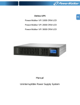
2-2. Hintere Konsolenansicht
Diagramm 1: 10000(L)/15000(L) Diagramm 2: 30000L Diagramm 3: 30000
/20000 (L)
Rear Panel
Diagramm 3: 10000(L)15000(L)/20000(L) Diagramm 4: 30000(L)
Input/Output Terminal Input/Output Terminal

IT
1. RS-232 Port
2. USB Port
3. Stecker für Not-Aus-Schalter (Emergency power off - EPO).
4. Share current port (only available for parallel model)
5. Parallel port (only available for parallel model)
6. Intelligent slot
7. Power stage fan
8. Externer Akkuanschluss
9. Bypass Input Circuit Breaker(Only available for dual input unit)
10. Eingang/Ausgang terminal ( Diagramm 2)
11. Eingangsicherung
12. Maintenance bypass switch
13. Output Grounding terminal
14. Output terminal: connect to mission-critical loads
15. Line input terminal
16. Bypass input terminal(Only available for dual input)
17. Input Grounding terminal
2-3. Single UPS Installation
Installation and wiring must be performed in accordance with the local electric laws/regulations and execute
the following instructions by professional personnel.
1) Make sure the mains wire and breakers in the building are enough for the rated capacity of UPS to
avoid the hazards of electric shock or fire.
NOTE: Do not use the wall receptacle as the input power source for the UPS, as its rated current is less than
the UPS’s maximum input current. Otherwise the receptacle may be burned and destroyed.
2) Switch off the mains switch in the building before installation.
3) Turn off all the connected devices before connecting to the UPS.
4) Prepare wires based on the following table:
Model
Wiring spec (AWG)
Input(Ph) Output(Ph) Neutral Battery Ground
10000
10
10
8
8
10000L 10 10 8 8 8
15000 8 8 6 6
15000L
8
8
6
6
6
20000
8
8
6
6
20000L 8 8 6 6 6
30000 8 8 4 4
30000L 8 8 4 4 4

6
EN
NOTE 1: The cable for 10000/10000L should be able to withstand over 40A current. It is
recommended to use AWG 10 or thicker wire for Phase and AWG 8 or thicker wire for Neutral for
safety and efficiency.
NOTE 2: The cable for 15000/15000L should be able to withstand over 63A current. It is
recommended to use AWG 8 or thicker wire for Phase and AWG 6 or thicker wire for Neutral for safety
and efficiency.
NOTE 3: The cable for 20000/20000L should be able to withstand over 63A current. It is
recommended to use AWG 8 or thicker wire for Phase and AWG 6 or thicker wire for Neutral for safety
and efficiency.
NOTE 4: The cable for 30000/30000L should be able to withstand over 63A current. It is
recommended to use AWG 8 or thicker wire for Phase and AWG 4 or thicker wire for Neutral for safety
and efficiency.
NOTE 5: The selections for color of wires should be followed by the local electrical laws and
regulations.
5) Remove the terminal block cover on the rear panel of UPS. Then connect the wires according to the
following terminal block diagrams: (Connect the earth wire first when making wire connection. Disconnect
the earth wire last when making wire disconnection!)
Terminal Block wiring diagram of 10000(L)/15000(L)/20000(L)
Terminal Block wiring diagram of 30000(L)

IT
For dual input unit, if there is two separate input, connect the Line input and bypass input respectively; if the
is only one common input, please connect the line input and bypass input together.
NOTE 1: Make sure that the wires are connected tightly with the terminals.
NOTE 2: Please install the output breaker between the output terminal and the load, and the breaker
should be qualified with leakage current protective function if necessary.
6) Put the terminal block cover back to the rear panel of the UPS.
Warning: (Only for standard model)
● Make sure the UPS is not turned on before installation. The UPS should not be turned on during wiring
connection.
● Do not try to modify the standard model to the long-run model. Particularly, do not try to connect the
standard internal battery to the external battery. The battery type and voltage may be different. If you
connect them together, it maybe causes the hazard of electric shock or fire!
Warning: (Only for long-run model)
● Make sure a DC breaker or other protection device between UPS and external battery pack is installed. If
not, please install it carefully. Switch off the battery breaker before installation.
NOTE: Set the battery pack breaker in “OFF” position and then install the battery pack.
● Pay highly attention to the rated battery voltage marked on the rear panel. If you want to change the
numbers of the battery pack, please make sure you modify the setting simultaneously. The connection
with wrong battery voltage may cause permanent damage of the UPS. Make sure the voltage of the
battery pack is correct.
● Pay highly attention to the polarity marking on external battery terminal block, and make sure the
correct battery polarity is connected. Wrong connection may cause permanent damage of the UPS.
● Make sure the protective earth ground wiring is correct. The wire current spec, color, position,
connection and conductance reliability should be checked carefully.
● Make sure the utility input & output wiring is correct. The wire current spec, color, position, connection
and conductance reliability should be checked carefully. Make sure the L/N site is correct, not reverse
and short-circuited.

8
EN
2-4. UPS Installation for Parallel System
If the UPS is only available for single operation, you may skip this section to the next.
1) Install and wires the UPSs according to the section 2-3.
2) Connect the output wires of each UPS to an output breaker.
3) Connect all output breakers to a major output breaker. Then this major output breaker will directly
connect to the loads.
4) Each UPS is connected to an independent battery pack.
NOTE: The parallel system can not use one battery pack. Otherwise, it will cause system permanent failure.
5) Refer to the following wiring diagram:
Wiring diagram of parallel system for 10000(L)/15000(L)/20000(L)

IT
Wiring diagram of parallel system for 30000(L)
2-5. Software Installation
For optimal computer system protection, install UPS monitoring software to fully configure UPS shutdown.

10
EN
3. Betrieb
3-1. Tastenbedienung
Button Function
ON/Enter Taste
Anschalten der USV: Drücken und halten Sie die ON/Mute Taste für mindesten
0,5 Sekunden, um die USV einzuschalten.
Auswahlbestätigen-Taste: Drücken Sie diese Taste. um die Auswahl in den
USV Einstellungen zu bestätigen.
OFF/ESC Taste
USV ausschalten: Drücken und halten Sie diese Taste für mindesten 0,5
Sekunden, um den Akkubetrieb der USV auszuschalten.
Drücken Sie diese Taste um die vorangegangene Auswahloptionen in den USV
Einstellungen aufzurufen
Test/Oben Taste
Akkutest: Drücken Sie die Test-Tasten gleichzeitig für 0,5 Sekunden um den
Selbsttest aufzurufen, währen sich die USV im Netzbetrieb oder
Konverter-Modus befindet.
Drücken Sie diese Taste um die nächste Auswahl in den USV Einstellungen
anzuzeigen.
Mute/Unten Taste
Stummschaltung des Alarms: Sobald die USV im Akkubetrieb ist, drücken und
halten Sie diese Taste für mindesten 0,5 Sekunde um den Alarm an oder
auszuschalten. Diese Taste beeinflusst nicht den Alarm für andere Warnungen
oder Fehlermeldungen.
Drücken Sie diese Taste um die letzte Auswahl in den USV Einstellungen
anzuzeigen.
Test/open +
Mute/unten Taste
Press and hold the two buttons simultaneous more than 1s to enter/escape the
setting menu.

IT
3-2. LCD Panel
LED Indicators:
There are 4 LEDs on front panel to show the UPS working status:
Modus LED Bypass Line Akkus Fehler
UPS An
●
●
●
●
Keine Ausgang Modus
○
○
○
○
Bypassmodus
●
○
○
○
AC Modus
○
●
○
○
Akkumodus
○
○
●
○
Konverter-Modus
○
●
○
○
Akku-Test
●
●
●
○
ECO Modus
●
●
○
○
Fehler
○
○
○
●
Note: ● means LED is lighting, and ○ means LED is faded.
LCD Panel:
LCD panel
LED indicators

12
EN
Anzeige
Funktion
Laufzeit
Zeigt die verbleibende Überbrückungszeit als Wert.
H: Stunde, M: Minute, S: Sekunde
Fehlermeldung
Zeigt Warnungen und Fehler an.
Zeigt Warnung- und Fehlerkodierung an. Die Kodes sind im Kapitel
3-9 detailliert aufgelistet.
Stummschaltung
Zeigt an, dass der USV-Alarm ausgeschaltet ist.
Ausgangs & Akkuspannung
Zeigt die Ausgangsspannung, Frequenz oder Akkuspannung an.
Vac: Ausgangsspannung, Vdc: Akkuspannung, Hz: Frequenz
Last
Zeigt die Last in 0-25%, 26-50%, 51-75% und 76-100% an.
Zeigt Überlastung an.
Zeigt einen Kurzschluss an USV oder angeschlossenen Geräten an.
Betriebsmodus
Zeigt an, dass das die USV an das Stromnetz angeschlossen ist.
Zeigt an, dass der Akku einwandfrei funktioniert.
Zeigt an, dass der Bypass einwandfrei funktioniert.
Zeigt an, dass der ECO-Modus aktiviert ist.
Zeigt an, dass der Inverterstomkreis einwandfrei funktioniert.
Zeigt an, dass der Ausgang einwandfrei funktioniert.

IT
Akku
Zeigt den Ladungszustand des Akkus in 0-25%, 26-50%, 51-75%,
und 76-100% an.
Zeigt einen Akkudefekt an.
Zeigt einen niedrigen Ladezustand und Spannung des Akkus an.
Eingangs- & Akkuspannung
Zeigt die Eingangsspannung oder -frequenz oder die
Akkuspannung an.
Vac: Eingangsspannung, Vdc: Akkuspannung, Hz: Eingangsfrequenz
3-3. Akustischer Alarm
Description
Buzzer status
Muted
UPS status
Bypassmodus
Ertönt alle 2 Minuten
Ja
Akkumodus
Ertönt alle 4 Sekunden
Fehler
Kontinuierlicher Ton
Warnungen
Überlastung
Ertönt zweimal jede Sekunde
Nein
Andere
Ertönt jede Sekunde
3-4. Single UPS Operation
1. Turn on the UPS with utility power supply (in AC mode)
1) After power supply is connected correctly, set the breaker of the battery pack at “ON” position (the
step only available for long-run model). Then set the line input breaker at “ON” position(for dual
input unit, also set the bypass input breaker at “ON”). At this time the fan is running and the UPS
enter to power on mode for initialization, several seconds later, UPS operates in Bypass mode and
supplies power to the loads via the bypass.
NOTE: When UPS is in Bypass mode, the output voltage will directly power from utility after you
switch on the input breaker. In Bypass mode, the load is not protected by UPS. To protect your
precious devices, you should turn on the UPS. Refer to next step.
2) Press and hold the “ON” button for 0.5s to turn on the UPS and the buzzer will beep once.
3) A few seconds later, the UPS will enter to AC mode. If the utility power is abnormal, the UPS will
operate in Battery mode without interruption.
NOTE: When the UPS is running out battery, it will shut down automatically at Battery mode. When the
utility power is restored, the UPS will auto restart in AC mode.
2. Turn on the UPS without utility power supply (in Battery mode)
1) Make sure that the breaker of the battery pack is at “ON” position (only for long-run model).
2) Press the “ON” button to set up the power supply for the UPS, UPS will enter to power on mode.
After initialization UPS will enter to No Output mode, then Press and hold the “ON” button for 0.5s
to turn on the UPS, and the buzzer will beep once.
3) A few seconds later, the UPS will be turned on and enter to Battery mode.

14
EN
3. Connect devices to UPS
After the UPS is turned on, you can connect devices to the UPS.
1) Turn on the UPS first and then switch on the devices one by one, the LCD panel will display total
load level.
2) If it is necessary to connect the inductive loads such as a printer, the in-rush current should be
calculated carefully to see if it meets the capacity of the UPS, because the power consumption of
this kind of loads is too big.
3) If the UPS is overload, the buzzer will beep twice every second.
4) When the UPS is overload, please remove some loads immediately. It is recommended to have the
total loads connected to the UPS less than 80% of its nominal power capacity to prevent overload
for system safety.
5) If the overload time is over acceptable time listed in spec at AC mode, the UPS will automatically
transfer to Bypass mode. After the overload is removed, it will return to AC mode. If the overload
time is over acceptable time listed in spec at Battery mode, the UPS will become fault status. At this
time, if bypass is enabled, the UPS will power to the load via bypass. If bypass function is disabled
or the input power is not within bypass acceptable range, it will cut off output directly.
4. Charge the batteries
1) After the UPS is connected to the utility power, the charger will charge the batteries automatically
except in Battery mode or during battery self-test.
2) Suggest to charge batteries at least 10 hours before use. Otherwise, the backup time may be
shorter than expected time.
3) Make sure the battery numbers setting on the control board (Please refer to the section 3-4-12 for
detailed setting) is consistent to real connection.
5. Battery mode operation
1) When the UPS is in Battery mode, the buzzer will beep according to different battery capacity. If the
battery capacity is more than 25%, the buzzer will beep once every 4 seconds; If the battery
voltage drops to the alarm level, the buzzer will beep quickly (once every sec) to remind users that
the battery is at low level and the UPS will shut down automatically soon. Users could switch off
some non-critical loads to disable the shutdown alarm and prolong the backup time. If there is no
more load to be switched off at that time, you have to shut down all loads as soon as possible to
protect the devices or save data. Otherwise, there is a risk of data loss or load failure.
2) In Battery mode, if buzzer sound annoys, users can press the Mute button to disable the buzzer.
3) The backup time of the long-run model depends on the external battery capacity.
4) The backup time may vary from different environment temperature and load type.
5) When setting backup time for 16.5 hours (default value from LCD panel), after discharging 16.5
hours, UPS will shut down automatically to protect the battery. This battery discharge protection
can be enabled or disabled through LCD panel control. (Refer to 3-7 LCD setting section)
6. Test the batteries
1) If you need to check the battery status when the UPS is running in AC mode/CVCF mode, you could
press the “Test” button to let the UPS do battery self-test.
2) Users also can set battery self-test through monitoring software.
7. Turn off the UPS with utility power supply in AC mode
1) Turn off the inverter of the UPS by pressing “OFF” button for at least 0.5s, and then the buzzer will
beep once. The UPS will turn into Bypass mode.
NOTE 1: If the UPS has been set to enable the bypass output, it will bypass voltage from utility
power to output terminal even though you have turned off the UPS (inverter).

IT
NOTE 2: After turning off the UPS, please be aware that the UPS is working at Bypass mode and
there is risk of power loss for connected devices.
2) In Bypass mode, output voltage of the UPS is still present. In order to cut off the output, switch off
the line input breaker(for dual input unit, also switch off the bypass line breaker). A few seconds
later, there is no display shown on the display panel and UPS is complete off.
8. Turn off the UPS without utility power supply in Battery mode
1) Turn off the UPS by pressing “OFF” button for at least 0.5s, and then the buzzer will beep once.
2) Then UPS will cut off power to output and there is no display shown on the display panel.
9. Mute the buzzer
1) To mute the buzzer, please press the “Mute” button for at least 0.5s. If you press it again after the
buzzer is muted, the buzzer will beep again.
2) Some warning alarms can’t be muted unless the error is fixed. Please refer to section 3-3 for the
details.
10. Operation in warning status
1) When Fault LED flashes and the buzzer beeps once every second, it means that there are some
problems for UPS operation. Users can get the warning indicator from LCD panel. Please check the
trouble shooting table in chapter 4 for details.
2) Some warning alarms can’t be muted unless the error is fixed. Please refer to section 3-3 for the
details.
11. Operation in Fault mode
1) When Fault LED illuminates and the buzzer beeps continuously, it means that there is a fatal error in
the UPS. Users can get the fault code from display panel. Please check the trouble shooting table
in chapter 4 for details.
2) Please check the loads, wiring, ventilation, utility, battery and so on after the fault occurs. Don’t try
to turn on the UPS again before solving the problems. If the problems can’t be fixed, please contact
the distributor or service people immediately.
3) For emergency case, please cut off the connection from utility, external battery, and output
immediately to avoid more risk or danger.
12. Operation of changing battery numbers
1) This operation is only available for professional or qualified technicians.
2) Turn off the UPS. If the load couldn’t be cut off, you should remove the cover of maintenance
bypass switch on the rear panel and turn the maintenance switch to “BPS” position first.
3) Switch off the line input breaker(for dual input unit, also switch off the bypass input breaker), and
switch off the battery breaker (only available for long-run model).
4) Remove the cabinet cover, and disconnect battery wire for standard model. Then modify the
jumper of JS3 on the control board to set the battery numbers as following table.
Note:1 = connect with jumper; 0 = no jumper; x = the pins are for other functions.
5) Modify the battery pack for the setting number carefully. After complete it, put the cover back,
switch on the battery breaker for long-run model.
Battery Number
in series
JS3
pin1 & pin2 pin3 & pin4 Pin5 & pin6 pin7 & pin8
18
1
0
0
X
19 0 1 0 X
20
0
0
1
X

16
EN
6) Switch on the line input breaker(for dual input unit, also switch on the bypass input breaker) and
the UPS will enter Bypass mode. If the UPS is in maintenance Bypass mode, turn the maintenance
switch to “UPS” position and then turn on the UPS.
3-5. Parallel Operation
1. Parallel system initial startup
First of all, please make sure all of the UPSs are parallel models and have the same configuration.
1) Turn on each UPS to AC mode respectively (Refer to section 3-4(1)). Then, measure the inverter
output voltage of each phase for each UPS to check if the inverter voltage difference between
actual output and setting value is less than 1.5V (typical 1V) with multimeter. If the difference is
more than 1.5V, please calibrate the voltage by configuring inverter voltage adjustment (Refer to
Program 15, 16 and 17, section 3-7) in LCD setting. If voltage difference remains more than 1.5V
after calibration, please contact your local distributor or service center for help.
2) Calibrate the output voltage measurement by configuring output voltage calibration (Refer to
Program 18, 19, and 20, section 3-7) in LCD setting to make sure the difference between real
output voltage and detected value of UPS is less than 1V.
3) Turn off each UPS (Refer to section 3-4(7.)). Then, follow the wiring procedure in section 2-4.
4) Remove the cover of parallel share current cable port on the UPS, connect each UPS one by one
with the parallel cable and share current cable, and then screw the cover back.
5) Turn on the parallel system in AC mode:
a) Turn on the line input breaker of each UPS(for dual input, also turn on bypass input breaker).
After all UPSs enter to bypass mode, measure the output voltage between two UPS for the
same phase to make sure the phase sequence is correct . If these two voltage differences are
near to zero, that means all connections are correct. Otherwise, please check if the wirings are
connected correctly.
b) Turn on the output breaker of each UPS.
c) Turn on each UPS in turns. After a while, the UPSs will enter to AC mode synchronously and
then, the parallel system is completed.
6) Turn on the parallel system in Battery mode:
a) Turn on the battery breaker (only available in long-run model) and output breaker of each UPS.
NOTE: It’s not allowed to share one battery pack for long-run UPSs in parallel system. Each UPS
should be connected to its battery pack.
b) Turn on any UPS. A few seconds later, the UPS will enter to battery mode.
c) Then, turn on another UPS. A few seconds later, the UPS will enter to battery mode and add to the
parallel system.
d) If you have the third UPS, follow the same procedure of c). Then, the parallel system is complete.
If more detailed information is needed, please contact supplier or service center for parallel
operation instruction.
2. Add one new unit into the parallel system
1) You can not add one new unit into the parallel system when whole system is running. You must cut
off the load and shutdown the system.
2) Make sure all of the UPS are the parallel models, and follow the wiring refer to section 2-4.
3) Install the new parallel system refers to the previous section.
3. Remove one unit from the parallel system
There are two methods to remove one unit from the parallel system:
First method:

IT
1) Press the “OFF” key twice and each time should be lasted for more than 0.5s. Then, the UPS will
enter into bypass mode or no output mode without output.
2) Turn off the output breaker of this unit, and then turn off the input breaker of this unit.
3) After it shuts down, you can turn off the battery breaker (for long-run model) and remove the
parallel and share current cables. And then remove the unit from the parallel system.
Second method:
1) If the bypass is abnormal, you can not remove the UPS without interruption. You must cut off the
load and shut down the system first.
2) Make sure the bypass setting is enabled in each UPS and then turn off the running system. All UPSs
will transfer to Bypass mode. Remove all the maintenance bypass covers and set the maintenance
switches from “UPS” to “BPS”. Turn off all the input breakers and battery breakers in parallel system.
3) Turn off the output breaker and remove the parallel cable and share current cable of the UPS which
you want to remove. Then, remove it from parallel system.
4) Turn on the input breaker of the remaining UPS and the system will transfer to Bypass mode. Set
the maintenance switches from “BPS” to “UPS and put the maintenance bypass covers back.
5) Turn on the remaining UPS according to the previous section.
Warning: (Only for the parallel system)
● Before turning on the parallel system to activate inverter, make sure that all unit’s maintenance switch
at the same position.
● When parallel system is turned on to work through inverter, please do not operate the maintenance
switch of any unit.
3-6. LCD-Display Index der Formulierungen
Abkürzung Anzeige Bedeutung
ENA
Aktivieren
DIS
Deaktivieren
ATO
Auto
BAT
Akku
NCF
Normal Modus
CF
Konverter-Modus
SUB
Subtract
ADD
Hintufugen
ON
An
OFF
Aus
FBD
Nicht erlaubt
OPN
Erlaubt
RES
Reserviert
N.L
Neutral Leitungsverlust
CHE
Prüfen
/