Page is loading ...

Power Supply Replacement Instructions
for the MLS 304/306/406
1. Disconnect the power cord from the switcher.
2. If the switcher is rack mounted, remove it from the rack.
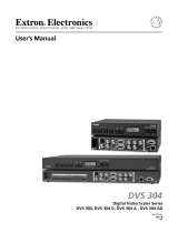
3. Remove the 14 screws (8 on the top and 3 on each side) that secure the
switcher’s top cover, as shown below.
Lift cover
straight up.
Remove (14)
screws from
top and sides.
4. Lift the cover straight up and off.
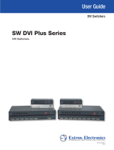
5. Disconnect both power supply cables, as shown below. Disconnect the two-
pin power input cable from the power supply. Disconnect the power supply
output cable from the switcher’s main PCB board (not the power supply).
Remove the
screw.
Power Supply to be Removed
Remove the screw.
Disconnect the
cable from the
main board
end.
Remove the screw.
Remove the screw.
Disconnect the
cable from the
power supply’s
2-pin connector.
6. Remove the four screws that secure the power supply to the base of the
switcher. Retain at least two of the screws for installation of the new power
supply.
Extron Electronics, USA
1230 South Lewis Street
Anaheim, CA 92805
800.633.9876 714.491.1500
FAX 714.491.1517
Extron Electronics, Europe
Beeldschermweg 6C
3821 AH Amersfoort, The Netherlands
+800.3987.6673 +31.33.453.4040
FAX +31.33.453.4050
Extron Electronics, Asia
135 Joo Seng Rd. #04-01
PM Industrial Bldg., Singapore 368363
+800.7339.8766 +65.6383.4400
FAX +65.6383.4664
Extron Electronics, Japan
Kyodo Building, 16 Ichibancho
Chiyoda-ku, Tokyo 102-0082
Japan
+81.3.3511.7655 FAX +81.3.3511.7656
www.extron.com
68-1262-04
Rev. A
09 07
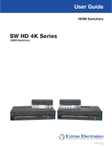
Install
standoffs (2).
Plug the PCB’s power output cable
to the power supply’s 2-pin power
input connector.
Install screws (2).
Plug the output
cable from fhe
power supply to
the PCB’s power
input connector.
10. Connect the switcher’s power output cable to the power supply’s 2-pin power
input connector. See the previous illustration.
11. Connect power output cable from the power supply to the switcher’s power
input connector. See the previous illustration.
12. Install the insulator and attaching screws that were removed in step 7.
Position insulator under
the heat sink.
Fasten the
insulator to the
standoffs.
Heat Sink
C The insulator must be tucked under the heat sink to protect components
from possible damage.
13.
Replace the top cover and reinstall the 14 screws removed in step 3.

If the optional 5-wire power output cable needs to be installed, replace the
power supply’s power output cable with the cable shown below.
A switcher PCB with part #20-601-xxx and the
MLS 306’s PCB both use a 6-pin power output
connector. Install the included optional 5-wire
output cable on the replacement power supply
for either switcher.
8b. The MLS 306 switcher requires that the included optional 5-wire power
output cable be installed on the replacement power supply. See the previous
cable illustration.
N The MLS 306 switcher’s PCB part number is not readily viewable
because of the multi-board arrangement. However, the MLS 306 uses a
6-pin power input connector, as shown` in the illustration below, and requires that
the replacement power supply’s optional 5-wire output cable be used.
The MLS 306 uses
a 6-pin power input
connector on its PCB.
9. Secure the replacement power supply to the switcher’s PCB using two of
the screws from step 6 and the two standoffs from step 7. The screws and
standoffs screw into the holes where the original power supply was attached.
See the following illustration.
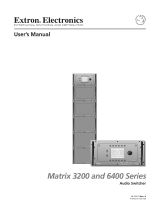
7. Remove and discard the two standoff hex nuts on the underside of the
replacement power supply board as shown below. Do not discard the stand-
offs to which the hex nuts were threaded or the power supply insulator and
the two attaching screws.
Remove hex nuts (2).
8. If the switcher is an MLS 304 or MLS 406, proceed to step 8a.
If the switcher is an MLS 306, proceed to step 8b.
8a. Check the part number on the switcher’s PCB. The part number indicates
which power output cable to use with the replacement power supply. The
replacement power supply is shipped with the 8-wire cable attached.
A PCB with part #20-730-xxx
uses an 8-pin power output
connector. Use the installed 8-wire
output cable on the replacement
power supply.
A PCB with part #20-601-xxx
uses a 6-pin power output
connector. Remove the installed
output cable on the replacement
power supply and use the optional
5-wire output cable included in
the kit.
/