Page is loading ...

CF2000
INSTALLATION MANUAL
Wheatley Hall Road
Doncaster
South Yorkshire
DN2 4NB
Tel 01302 321 541
www.cooperfire.com
Assessed to ISO 9001:2000
Certification number 714h/02
Document Drg Ref PR200-50-502-20
QUALITY
MANAGEMENT
0832 – CPD – 1089
EN54-2 1997 & A1;2006
EN54-4:1997 & A1;2002 A2:2006
Approved to
P 8

Introduction to the Manual
CF2000
Analogue Addressable Fire Detection System
This manual provides information on the installation, operation and
maintenance of the Cooper Fire Systems CF2000 System.
NOTICE
The operating system of the CF2000 may be revised as a result of
enhancements to the system software or hardware. Revisions to this
manual will be issued and supplied on request and should be logged
in the table supplied on the contents page.
Introduction
CAUTION
RISK OF EXPLOSION IF BATTERY IS REPLACED
BY AN INCORRECT TYPE
DISPOSE OF THE USED BATTERIES ACCORDING
TO THE INSTRUCTIONS ( Appendix Page 92 )

Contents
Contents Page
1.0 System Design & Installation 5
Introduction 6
Project Planning 7
System Design Guidelines 8
Compatible Equipment 9
Detectors 10
Call Points 14
Sounders 16
Interfaces 17
3 Channel I/O 17
1 Channel I/O 17
Zone Monitor Unit 18
Shop Unit Interface 18
Spur Isolater 19
4 Way Sounder Circuit 19
20
21
24
26
28
Equipment Compatiblity
System Overview
Technical Specification
Optional Functions
External Connections
Installation
29
Fixing details
30
System Wiring
31
2.0 Commissioning CF2000
33
Commissioning Software
34
Panel Fault Finding
38
Protocol
39
3.0 Panel Controls and Indicators
40
41
42
43
44
44
46
47
48
50
51
52
Panel Controls and
Indicators System Healthly
View Event
Fire Event
View Fires
View Pre-Alarm
View Fault
View Disabled Address View
Disabled Zone
View Disabled I/O
View Log
Operations
Soft Reset
53
Evacuate
54
Silence Alarms
55
Lamp Test
56
Weekly Test
57

Contents
Contents Page
Access Level 2
Commissioning
59
Panel Settings
Erase Log
60
Change Password
61
Change Lanuage
62
Date Time
63
System Details
64
Testing
Testing Device
65
Test Zone
66
Test Sound Levels
67
One Man Walk Test
68
Global Flashing LED
69
Analogue Levels
70
Device Config
71
72
Add Device
Delete Device
4.0 Appendix
73
74
75
76
77
78
79
80
81
82
83
84
85
86
Spur Isolator
4 Way Sounder Controller
Zone Monitor Unit
Shop Monitor Unit
1 Way Input Output Unit
Sensor Base Wiring
System Wiring
IP66 Wall Sounder
Internal Wall Sounder
Base Sounder Wiring
3 Way Input Output Unit
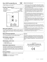
Loop Powered Beacon Call
Point
CE Marking
Battery Disposal Instructions
87
88

System Installation and Design
Section 1
5

Introduction
CF2000 provides all of the sophisticated features required of a leading edge analogue
addressable fire system along with the simple operation and neat installation
demanded by installers and building users.
The panel can be flush or surface mounted and the generously sized metal back box
allows ample facilities for rear or top cable entries.
It is available as a two loop panel with or without an integral printer.
A comprehensive range of ancillary devices is available to operate with the CF2000
panel, including Optical, Ionisation, photo-thermal and heat sensors, callpoints and a
comprehensive range of interfaces.
Each of the CF2000 system components has been specifically designed to operate as
part of a CF2000 system, this provides an assurance that the panel, the sensor, the
interfaces and the ancillaries are all fully compatible with each other and that the full
range of system functionality is supported by each device.
Each loop of a CF2000 panel can accommodate up to 200 (99 Belgium) addresses.
6

Project Planning
The following is a typical program and timetable for a CF2000 installation project, once
the initial order has been received:
1. Project Meeting
Installer and user to be present; system specifications, schematic diagram and
proposed circuit drawing to be available. CF2000 Installation & Commissioning
Guide to be provided.
2. Equipment Fix
Typically 2 week's notice is required for equipment to be delivered. Cable to be
installed and bases/back boxes to be fitted. Then fire sensors, call points, alarm
sounders and interface units can installed.
3. Address Schedule
Schedule of sensor locations to be completed by installer and returned to enable
System programming.
4. Auto Learn
Fire panel/repeater panels to be installed and terminated. System to be powered
up by installer and auto learn mode activated (see Auto Learn section). System
to be tested and verified by installer, prior to final commissioning.
5. Final Commissioning
Minimum 2 weeks notice is required from receipt of Address Schedule and
Commission request form for a Cooper Fire Systems Service Engineer to attend
site to implement/oversee the final commissioning procedures (see
Commissioning section), in conjunction with the installer.
7

Guidelines
Systems should to the relevant local standards and codes of practice, for the UK this is
BS5839 part 1. CF2000 meets all the relevant requirements of BS5839 part 1: 2002.
Installation planning is simplified by the fact that every addressable CF2000 device contains an
integral short circuit isolator. Care must be taken to ensure that local standards requirements
regarding aspects such as loop coverage, area covered by a single spur and cable
specification are observed.
There may be certain applications in which deviations from the code may be necessary and
these must be listed on the commissioning certificate. (See commissioning section)
Loop lengths
The maximum permitted loop length is 2 km measured from the near to the far terminals on the
CF2000 Motherboard PCB. There is no minimum limit to loop length. Any wiring spurs off the
loop must be included within the 2 km limit. On long loop runs, the lengths of wiring rises and
falls (between floors, down to manual call points) must be included. Remember to include
these especially when taking loop lengths from plan drawings.
Loop loading - total number of addresses
The total number of addresses per loop is 200 (99 Belgium). this includes detectors, call points
and all other addressable items and call points. When designing systems its recommended
that allowances are made for future expansion, Short circuit isolators are incorporated into
every CF2000 loop device, including Smoke detectors, heat detectors, sounders, callpoints
and interfaces. Therefore, no further fault protection is required , in the event of a single fault,
none of the devices connected to the loop will fail to operate as the fault will be isolated by the
two adjacent devices.
Spur connected devices downstream of a cable fault will cease to function.
System Design Guidelines
8

Compatible Equipment
Addressable Ca ll Points
CBG370 Addressable call point - Flush 85(H) x 85(W) x 30(D)
CBG370/S Addressable call point - Surface 85(H) x 85(W) x 53(D)
CBG370/W P W eatherproof addressable call point 108(H) x 108(W ) x 65(D)
Ana logue Sensors
CAH330 Analogue heat detector 101 Dia x 43(D)
CAP320 Analogue optical smoke detector 101 Dia x 33(D)
CAI310 Analogue ionization smoke detector 101 Dia x 33(D)
CAPT340 Analogue photo/thermal dual detector 101 Dia x 43(D)
CAB300 Common mounting base 104 Dia x 22(D)
Addressable Inte rfa ce s
CSI350 Spur Isolator 85(H) x 145(W ) x 58(D)
CIO351 3 Channel I/O Unit 130(H) x 180(W ) x 60(D)
CZMU352 Zone Monitor Unit 85(H) x 145(W ) x 58(D)
CMIO353 230v Relay I/O Unit 130(H) x 180(W ) x 60(D)
CSC354 4 W ay Sounder Controller 300(H) x 300(W ) x 74(D)
CSUM355 Shop Unit Monitor 130(H) x 180(W ) x 60(D)
Addressable Sounde rs a nd Bea cons
CAS380 Loop Mounted Base Sounder 102 Dia x 40(D)
CAS381 W all Sounder 105(H) x 105(W ) x 95(D)
CAS381/W P W all Sounder - weatherproof 110(H) x 110(W ) x 105(D)
CAB382 Loop Mounted Beacon 93 Dia x 53(D)
CASBB384 Loop Mounted Base Sounder/Beacon 115 Dia x 35(D)
CASB383 Wall Sounder/Beacon 106(H) x 106(W ) x 91(D)
CASB383/W P W all Sounder/Beacon IP66 110(H) x 110(W ) x 100(D)
Conventional Ca ll Points
CBG375 Flush mounting call point 87(H) x 87(W ) x 20(D)
CBG375/S Surface mounting call point 87(H) x 87(W ) x 53(D)
CBG376 W eatherproof surface call point 110(H) x 110(W ) x 65(D)
Conventional De tectors
CPD320 Photoelectric smoke detector 101 Dia x 33(D)
CID310 Ionization smoke detector 101 Dia x 33(D)
CPT340 Combined photo/thermal detector 101 Dia x 43(D)
CFR330 Fast response heat detector 101 Dia x 43(D)
CMT360 Medium response heat detector 101 Dia x 43(D)
CHT390 High temperature heat detector 101 Dia x 43(D)
CDBB300 Common mounting base 104 Dia x 22(D)
Conventional Sounde rs
AC/R 24V flush mounting electronic sounder 86(H) x 86(W ) x 42(D) *
CXBB/R Surface mounting back box for AC/R
SY/R 24V low current sounder 105(H) x 105(W ) x 95(D)
SQ/R Base sounder 112 Dia x 30(D)
ROLP/R/S Electronic sounder - shallow base for indoor applications 93 Dia x 75(D)
ROLP/R/D Electronic sounder - deep base (W eatherproof) 93 Dia x 105(D)
Conventional Sounde r/Be acons
FL/RL/R/D Combined sounder/beacon deep base 93 Dia x 92(D)
FL/RL/R/S Combined sounder/beacon Shallow base 93 Dia x 121(D)
9

CPD320 Conventional Photoelectric Detector, this is the
most commonly used detector and is most suitable for
detecting slow burning fires.
The range of compatible detectors for the CF2000 system consists of the following:
CPT340 Conventional Photo/thermal Detector, this is a
new addition to the Cooper Fire Systems range of
detectors. It is the ideal detector for a multi-use
environment as it has an excellent response to
smouldering and fast burning fires.
CMT360 77°C Fixed Conventional Heat Detector,
Heat detectors are suitable for dusty environments or
environments where smoke is likely to be present under
normal operating conditions.
Compatible Equipment
Conventional Devices
Model CID310 CPD320 CFR330 CMT360 CHT390 CPT340
Operating voltage
Standby current (max) 70µA
Start-up Current (max 20 seconds) 340µA
Alarm current (max) 20mA
Ambient Temperature (max) 45ºC 60ºC 75ºC 75ºC
Ambient Temperature (min)
Alarm temperature (static)
60ºC
77ºC
Heat detector class
as defined by EN54-5:2000
Radioactive material/strength Am 18.5KBq
Relative humidity (non cond)
Height (w/o base)
Height (with base)
Diameter
Weight (w/o base) 86g 78g 78g
Material
Colour
76g
15 to 30V dc
25mA
30µA
210µA N/A
47mm 56mm
100mm
N/A
N/A
60ºC
-20ºC
34mm
White
90ºC
N/A
0 to 95%
43mm
A2R BS CS A2S
PC/ABS
10

CHT390 92°C Fixed Conventional Heat Detector,
Heat detectors are suitable for dusty environments or
environments where smoke is likely to be present under
normal operating conditions.
CFR330 Rate of Rise A2R Heat Detector,
Heat detectors are suitable for dusty environments or
environments where smoke is likely to be present under
normal operating conditions.
CDBB300 Conventional Detector Base,
Compatible Equipment
Conventional Devices
11

CAP320 Analogue Photoelectric Sensor, this is the most
commonly used sensors and is most suitable for detecting
slow burning fires.
The status LED can be programmed to either be
permanently off under normal conditions or to pulse in
order to confirm that it is in communication with the
CF2000 control panel.
The range of compatible sensors for the CF2000 system consists of the following:
CAPT340 Analogue Photo/thermal Sensor, this is a new
addition to the Cooper Fire Systems range of sensors. It is
the ideal sensor for a multi-use environment as it has an
excellent response to smouldering and fast burning fires.
Photo/thermal sensors can be programmed for thermal
only operation at certain times of day
The status LED can be programmed to either be
permanently off under normal conditions or to pulse in
order to confirm that it is in communication with the
CF2000 control panel.
Compatible Equipment
Analogue Devices
Model CAI310 CAP320 CAH330 CAPT340
Operating voltage
Standby current (max)
Alarm current (max)
A1R 50ºC
BS 65ºC
CS 80ºC
Ambient Temperature (min)
A1R 60ºC
BS 77ºC
CS 90ºC
Heat sensor class
as defined by EN54-5:2000
Radioactive material/strength Am 18.5KBq
Relative humidity (non cond)
Height (w/o base)
Height (with base)
Diameter
Weight (w/o base) 86g 78g 76g 78g
Material
Colour
18 TO 30V dc
220µA
5mA
-20ºC
N/A
A1R, BS, CS
control panel
selectable
A2S
PC/ABS
0 to 95%
34mm 43mm
N/A
White
50ºC60ºCAmbient Temperature (max)
N/A 60ºCAlarm temperature (static)
47mm 56mm
100mm
12

CAH330 Analogue Heat Sensor,
Heat sensors are suitable for dusty environments or
environments where smoke is likely to be present under
normal operating conditions. The CAH330 can be
programmed to operate in A1R,BS or CS mode of
operation depending on the required application and
sensitivity requirements.
The status LED can be programmed to either be
permanently off under normal conditions or to pulse in
order to confirm that it is in communication with the
CF2000 control panel.
CAB300 Analogue Sensor Base,
Compatible Equipment
Analogue Devices
Short Circuit Isolators
Each of the sensors in his range contain an integral short circuit isolator, which operates between the
-VE COM IN terminal and the -VE COM OUT terminal. The isolator operates in conjuction with the
CF2000 Control Panel when a low parallel resistance fault of typically 200W is presented between the
+VE and -VE of the loop wiring.
Short Circuit Isolation Data
(Integral with each sensor)
Total Loop Resistance for correct
operation of short circuit isolator
50Ω (max)
Continuous Current allowable through
isolator
700mA (max)
Isolator Resistance in closed state 0.13Ω (max)
Leakage Current into direct short
circuit with isolator open
13mA (max)
Parallel Fault Resistance to be seen
at the Control Panel for isolators to
open
200Ω (typ)
13

Compatible Equipment
Compatible callpoints
The range of purpose designed callpoints for CF2000 consists of a surface callpoint, a
flush callpoint and a surface weatherproof callpoint.
A range of accessories is available including a hinged protective cover, Resettable
element kit and a flush bezel.
Compatible Sounders
A wide range of sounders are available to operate with CF2000.
All sounders have multiple selectable volume settings, the volume setting is controlled
by the CF2000 panel and so can be altered without needing to access the sounder.
Conventional
CBG375
CBG375/S
CBG376/WP
14

Compatible Equipment
Compatible callpoints
The range of purpose designed callpoints for the CF2000 consists of a surface callpoint,
a flush callpoint and a surface weatherproof callpoint.
A range of accessories is available including a hinged protective cover, Resettable
element kit and a flush bezel.
The status LED can be programmed to either be permanently off under normal
conditions or to pulse in order to confirm that it is in communication with the CF2000
control panel.
Compatible Sounders and Beacons
A wide range of loop powered sounders and beacons are available to operate with the
CF2000 consisting of a combined sounder base with a maximum output of 95 dB(A), a
standalone sounder with a maximum output of 100 dB(A) that is available in standard or
weatherproof versions and a stand alone loop powered beacon.
For applications where a discreet dedicated sounder is required, a cover plate is
available for the white base mounted sounder enabling it to be used as a stand alone
wall or ceiling mounted sounder.
All of these devices are fully programmable via the sophisticated CF2000 multi stage
cause and effect programming facilities.
All sounders have multiple selectable volume settings, the volume setting is controlled
by the CF2000 panel and so can be altered without needing to access the sounder.
CBG370
CBG370/S
CBG370/WP
Analogue
15

Base sounder
The CAS380 has been designed specifically to complement the latest generation of
Cooper Fire Systems soft addressed detectors.
it consists of a first fix bracket, and a main body which clips onto the bracket
incorporating the sounder and a detector mounting base in a single composite
assembly.
After the body has been clicked into place and connected, a sensor or front cover is
then added to complete a very simple quick and neat installation.
The cover enables the CAS380 to be used as a discreet stand alone wall or ceiling
mounted device.
The sounder base design incorporates a mechanism that can be activated if required to
lock either the sensor or the cover into place to prevent unauthorised removal.
Dedicated Stand alone sounders
Stand alone sounders are ideal for applications where greater sound outputs are
required than can be achieved with a base sounder or for applications requiring a higher
level of resilience or ingress protection.
Two different versions are available standard version and an IP66 rated version.
CAS380
CAS381
CAS381/WP
CAS380 with sensor fitted
CAS380 with CASC fitted
Compatible Equipment
16

Interfaces
CF2000 has been designed to be suitable for a wide range of applications, various
interfaces have been developed to enable the simple integration of other fire systems or
building control and safety systems. The following devices are available:
3 Channel I/O device. (CIO351)
CIO351 has 3 input channels and 3 output channels, it is used to monitor up to three
separate inputs from equipment such as sprinkler flow switches and also to provide 3
separately controlled volt free output contacts which are intended to be used to control
external equipment such as air handling plant or access control systems.
All inputs and outputs operate completely independently of each other and can be
programmed using the sophisticated cause and effect capabilities of CF2000 to operate
either globally or in response to activation of specific devices or specific inputs.
Inputs are monitored for open and short circuits, a specific resistance is required to
activate an alarm condition, fully open or short circuit conditions are monitored and
generate a system fault signal.
Inputs are suitable for use as fire signal inputs such as from a sprinkler flow switch ,
however they can also be used to monitor non fire inputs such as external keyswitches.
Outputs are rated to switch a maximum of 1A resistive at 30V DC.
The CIO351 is supplied in a surface mounting IP65 box.
1 Channel I/O device with mains rated switching capability
(CMIO353)
CMIO353 is a single channel input / output unit, the output is capable of switching up to
1A at 230V AC.
Commonly used for applications such as door release controls and plant shut down
signaling
The input is monitored for open and short circuits, a specific resistance is required to
activate an alarm condition, fully open or short circuit conditions are monitored and
generate a system fault signal.
The input is suitable for use as a fire signal input such as from a sprinkler flow switch,
however it can also be used to monitor non fire inputs such as an external keyswitch.
The CIO353 is supplied in a surface mounting IP65 box.
CIO351
CMIO353
17

Zone monitor unit (CZMU352)
CZMU352 is designed to enable a zone of compatible conventional detectors and
callpoints to be connected into the CF2000 loop, it is compatible with up to 20 Cooper
Fire Systems conventional detectors connected via CDBB300 bases.
Please refer to local standards e.g.BS5839 Pt1:2002 for details of the maximum
allowable area to be covered by a single spur / zone. CZMU352 fixes to a standard,
deep, double gang back box and can be either surface or semi recess mounted. When
semi recessed only the front section protrudes giving a maximum 29mm depth.
Shop unit Interface (CSUM355)
CSUM355 accepts a zone of conventional detectors plus an unlimited number of
callpoints which can be connected to the same input as the detectors or a separate
callpoint input if required.
It also has a 24V 1A rated relay output, and a facility to connect a power supply, which
can then be monitored for fault.
In addition it has the facility to connect two circuits of conventional polarised sounders,
which are monitored by means of an end of line resistor and powered in alarm
conditions from the external power supply.
The sounder circuits can be programmed to operate in pulsed, continuous or time
delayed mode.
Please refer to local standards e.g. BS5839 Pt1:2002 for details of the maximum
allowable area to be covered by a single spur / zone. The CSUM355 is supplied in a
surface mounting IP65 box.
Interfaces
CSUM355
CZUM352
18
(CZMU352)

Spur Isolator (CSI350)
CSI350 enables soft addressing to work when the loop contains spurs, it controls the
addressing operation so that when the system reaches a spur, all devices on the spur
are allocated an address before it continues addressing the loop.
The device also incorporates a short circuit isolator.
Because each device contains a short circuit isolator only 1 is required at the start of
each spur.
CSI350 is mounted on a standard deep double gang back box (supplied)
Please refer to BS5839 Pt1:2002 for details of the maximum allowable area to be
covered by a single spur / zone
4 Way sounder circuit controller (CS354)
CSC354 provides power for 4 separately controllable conventional sounder circuits,
each circuit can be separately programmed.
CSC354 is designed to greatly simplify installation in applications where specialist
sounders or beacons are required since it powers the sounders and allows full control of
the sounder operation without having to wire the sounder back to the CF2000 control
panel.
A 4 way unit takes up a single address but each circuit can be independently controlled.
An CSC354 unit requires a local un-switched 230V supply and incorporates a back up
battery to 24 hours of standby operation followed by a minimum of 30 minutes of full
alarm ringing.
A standby of 72 hours can be achieved at the expense of reduced load capability.
Interfaces
CSI350
CSC354
19

Equipment Compatibility
Sensors
Loop wired sensors must be of the Cooper Fire Systems 300 series soft addressed
analogue type. Cooper Fire Systems 300 series conventional detectors can be
connected via an CZMU352 interface. The connection of other detector types via an
CZMU352 interface is not recommended,
Call points
Loop wired call points must be the Cooper Fire Systems 300 series soft addressed
analogue type, Cooper Fire Systems 300 series conventional callpoints can be
connected via an CZMU352 interface. The connection of other callpoint types via an
CZMU352 interface is not recommended,
Sounders
Loop powered addressable sounders must be of the Cooper Fire Systems 300
series soft addressed analogue type.
Conventional sounders can also be connected either to the conventional sounder
circuits at the panel or to the loop via a CSC354 addressable sounder controller
interface providing they meet the following:
1) They are suitable for operation between 18V and 28V.
2) They are polarised and suppressed.
3) The total alarm load is less than the rating of the panel / Alarm Power Interface.
Note: It is possible to use devices outside these requirements if they are supplied
with power from a separate source and switched via a suitable relay.
Relay circuits
Additional relays can be added to the CF2000 system by using either CMIO353 or
CIO351 relay units.
Relays / Auto-dialers and auxiliary equipment
A wide variety of relays and other equipment can be connected to the CF2000
system, but you should note the following constraints:
1) CF2000 provides monitored outputs to drive fire and fault relays mounted in
external equipment. External relays should be suppressed. If a non-suppressed
relay is used then a diode can be connected , to suppress any reverse EMF on the
release of the relay which might cause the panel to malfunction.
2) A 24V DC output is provided at the panel to make it easy to connect ancillary
equipment. Although the panel can supply a continuous quiescent load of up to
30mA, BS5839 precludes this practice and any ancillary equipment you connect
should only consume power in the alarm or fault mode to meet the requirements of
BS5839.
20
/