ABB Relion 611 series REB611 User manual
- Category
- Measuring, testing & control
- Type
- User manual

Relion
®
611 series
Busbar and Multipurpose Differential
Protection and Control
REB611
Product Guide

Contents
1. Description.....................................................................3
2. Standard configuration...................................................3
3. Protection functions........................................................5
4. Application.....................................................................5
5. Supported ABB solutions...............................................8
6. Control...........................................................................9
7. Measurement.................................................................9
8. Disturbance recorder....................................................10
9. Event log......................................................................10
10. Recorded data............................................................10
11. Trip circuit supervision and measurement circuit
supervision..................................................................10
12. Self-supervision...........................................................10
13. Access control............................................................10
14. Inputs and outputs......................................................11
15. Communication...........................................................11
16. Technical data.............................................................13
17. Local HMI....................................................................26
18. Mounting methods......................................................26
19. IED case and IED plug-in unit......................................27
20. Selection and ordering data.........................................28
21. Accessories and ordering data....................................29
22. Tools...........................................................................30
23. Terminal diagram.........................................................32
24. References..................................................................32
25. Functions, codes and symbols....................................33
26. Document revision history...........................................34
Disclaimer
The information in this document is subject to change without notice and should not be construed as a commitment by ABB. ABB assumes no responsibility for any
errors that may appear in this document.
© Copyright 2012 ABB.
All rights reserved.
Trademarks
ABB and Relion are registered trademarks of the ABB Group. All other brand or product names mentioned in this document may be trademarks or registered
trademarks of their respective holders.
Busbar and Multipurpose Differential Protection and Control 1MRS757467 B
REB611
Product version: 1.0
2 ABB

1. Description
REB611 is a dedicated busbar protection IED
(intelligent electronic device) designed for phase-
segregated short-circuit protection, control, and
supervision of single busbars. REB611 is intended
for use in high-impedance-based applications
within utility substations and industrial power
systems. In addition, the IED can be utilized in
restricted earth-fault and residual earth-fault
applications for the protection of generators,
motors, transformers and reactors.
REB611 is a member of ABB’s Relion
®
product
family and part of the 611 protection and control
product series. The 611 series IEDs are
characterized by their compactness and
withdrawable-unit design.
The 611 series is designed to offer simplified but
powerful functionality intended for most
applications. Once the application-specific
parameters have been entered, the installed IED
is ready to be put into service. The further
addition of communication functionality and
interoperability between substation automation
devices offered by the IEC 61850 standard adds
flexibility and value to end users as well as
electrical system manufacturers.
2. Standard configuration
REB611 is available in one standard configuration.
To increase the user-friendliness of the IED’s
standard configuration and to emphasize the
IED's simplicity of usage, only the application-
specific parameters need setting within the IED's
intended area of application.
The standard signal configuration can be altered
by LHMI (human-machine interface), WHMI (Web
browser-based user interface) or the optional
application functionality of the Protection and
Control IED Manager PCM600.
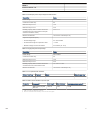
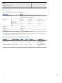
Table 1. Standard configuration
Description Std. conf.
High-impedance differential A
Busbar and Multipurpose Differential Protection and Control 1MRS757467 B
REB611
Product version: 1.0 Issued: 2012-05-04
Revision: B
ABB 3

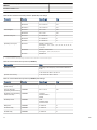
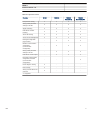
Table 2. Supported functions
Functionality Conf. A
Protection
1)
High-impedance differential protection, instance 1 ●
High-impedance differential protection, instance 2 ●
High-impedance differential protection, instance 3 ●
Non-directional earth-fault protection, low stage, instance 1
●
2)
Non-directional earth-fault protection, high stage, instance 1
●
2)
Circuit breaker failure protection ●
Master trip, instance 1 ●
Master trip, instance 2 ●
Control
Circuit-breaker control ●
Supervision
Trip circuit supervision, instance 1 ●
Trip circuit supervision, instance 2 ●
CT supervision for high-impedance protection scheme, instance 1 ●
CT supervision for high-impedance protection scheme, instance 2 ●
CT supervision for high-impedance protection scheme, instance 3 ●
Measurement
Disturbance recorder ●
Three-phase current measurement, instance 1
3)
●
Residual current measurement, instance 1 ●
● = Included
1) The instances of a protection function represent the number of identical function blocks available in a standard configuration.
2) Io selectable by parameter, Io measured as default.
3) In REB611, CMMXU is used for measuring differential phase currents.
Busbar and Multipurpose Differential Protection and Control 1MRS757467 B
REB611
Product version: 1.0
4 ABB

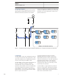
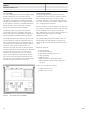
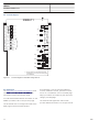
3. Protection functions
The IED offers phase-segregated (three phases)
high-impedance differential protection and non-
directional earth-fault protection for busbars,
motors and generators. REB611 also offers high-
impedance differential-based restricted earth-fault
protection for motors, generators, reactors and
power transformers.
Lockout
relay
86
Hi> 87
Hi> 87
Hi> 87
MCS 1I MCS 1I
3I>BF 51BF
Io>BF
51N
BF
Io>>> 50N
Io> 51N-1
3
3
3
3
REB611 (STANDARD CONF A)
GUID-E0FA94F1-428D-4BA3-82EF-F5DAB1CABDC7 V1 EN
Figure 1. Protection function overview of standard configuration A in a single zone with bus-wire supervision
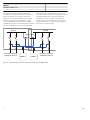
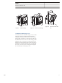
4. Application
The IED REB611 offers bus-differential protection
in a single zone with bus-wire supervision. It also
offers the possibility of bus-differential protection
over two zones using two REB611 IEDs.
The IED REB611 can be used in the protection of
a motor or generator using the combined
restricted earth-fault and residual earth-fault
protection functionalities. Due to the individuality
of the high-impedance protection functions, a
single REB611 can be used for restricted earth-
fault protection of both the high and low voltage
side of a power transformer.
The high-impedance principle for busbar
differential protection provides a secure and
dependable protection scheme against faults
within the measured zone. The high-impedance
principle has been used for many years for
differential protection due to the capability to
manage through-faults also with heavy current
transformer (CT) saturation.
The IED REB611’s high-impedance protection
functions contain built-in blocking functionality,
which is provided by the bus-wire supervision
functions to restrict faulty operations in case of
faults in the measurement circuits.
Busbar and Multipurpose Differential Protection and Control 1MRS757467 B
REB611
Product version: 1.0
ABB 5

An additional stand-by (residual) earth-fault
protection is provided by the two non-directional
earth-fault stages. The stand-by earth-fault
protection can be used together with the high-
impedance protection functionality to protect
motors, generators and transformers against
residual earth-faults. The measurements are taken
from the earthing point of the protected object.
The residual earth-fault protection can also be
used as bus-wire supervision, especially in new or
retrofitting applications, where an earth-fault
protection function is used for grounding the
measurement circuits where short-circuiting or
circuit breaks have occurred. The grounding can
be done by an external relay.
Zone B
3
3 3
Incoming / Outgoing
Feeder for Zone A
REB611 REB611
Incoming / Outgoing
Feeder for Zone B
3
3
3
Zone A
Bus coupler
GUID-9D830E6D-F3C4-45D3-879E-FA6C6F140114 V1 EN
Figure 2. Bus-differential protection covering two zones with two REB611 IEDs
Busbar and Multipurpose Differential Protection and Control 1MRS757467 B
REB611
Product version: 1.0
6 ABB

Hi> 87
3
3
Io>BF
Lockout
relay
86
REB611 (STANDARD CONF A)
1
1
MCS 1I MCS 1I
3I>BF 51BF
Hi> 87
Hi> 87
MCS 1I MCS 1I
MCS 1I MCS 1I
Io> 51N-1 Io>>> 50N
51N
BF
GUID-9F68C879-2144-468C-9441-0BD7CB201E98 V1 EN
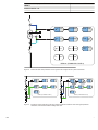
Figure 3. Restricted earth-fault protection of the high and low voltage side of a power transformer
REB611 (STANDARD CONF A) REB611 (STANDARD CONF A)
3
1
3
3
Lockout
relay
86
G
Hi> 87
Hi> 87
MCS 1I MCS 1I
3I>BF 51BF
Io>BF
51N
BF
Io>>> 50N
Io> 51N-1
1
1
G
Lockout
relay
86
Hi> 87
Hi> 87
Hi> 87
MCS 1I MCS 1I
3I>BF 51BF
Io>BF
51N
BF
Io>>> 50N
Io> 51N-1
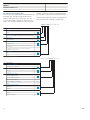
GUID-55BADD92-9638-443A-9EB2-026DEA615AC3 V1 EN
Figure 4. Protection of two generators, one with restricted earth fault and the other with high-impedance
differential, both combined with standby earth fault
Busbar and Multipurpose Differential Protection and Control
1MRS757467 B
REB611
Product version: 1.0
ABB 7

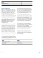
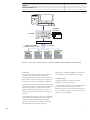
5. Supported ABB solutions
ABB’s 611 series protection and control IEDs
together with the COM600 Station Automation
device constitute a genuine IEC 61850 solution
for reliable power distribution in utility and
industrial power systems. To facilitate and
streamline the system engineering, ABB’s IEDs
are supplied with Connectivity Packages
containing a compilation of software, IED-specific
information and a full IED data model including
event and parameter lists. By utilizing the
Connectivity Packages, the IEDs can be readily
configured via the PCM600 Protection and
Control IED Manager and integrated with the
COM600 Station Automation device or the
MicroSCADA Pro network control and
management system.
The 611 series IEDs offer native support for the
IEC 61850 standard, including limited binary
GOOSE messaging. Compared with traditional
hard-wired inter-device signaling, peer-to-peer
communication over a switched EthernetLAN
offers an advanced and versatile platform for
power system protection. The 611 series IED’s
implementation of the IEC 61850 substation
automation standard enables access to some
distinctive features that include fast software-
based communication, continuous supervision of
the integrity of the protection and communication
system, and inherent flexibility for reconfiguration
and upgrades.
The customizable graphical display of the Web
browser-based HMI of COM600 presents a single-
line diagram feature that is especially useful for
the 611 series IEDs because of the limited size of
the LHMI. Further, the WHMI of COM600 offers
an overview of the whole substation, including
IED-specific single-line diagrams, thus enabling
convenient information accessibility.
To enhance personnel safety, the WHMI also
enables remote access to substation devices and
processes. Furthermore, COM600 can be used
as a local data warehouse for technical
documentation of the substation and for network
data collected by the IEDs. The collected network
data facilitates extensive reporting and analyzing
of network fault situations using the data and
event handling features of COM600.
The data historian can be used for accurate
process performance monitoring by following
process and equipment performance calculations
with real-time and history values. Better
understanding of the process behaviour by joining
time-based process measurements with
production and maintenance events helps the
user to understand the process dynamics.
COM600 also features gateway functionality
providing seamless connectivity between the
substation IEDs and network-level control and
management systems such as MicroSCADA Pro
and System 800xA.
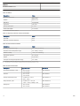
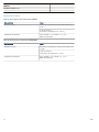
Table 3. Supported ABB solutions
Product Version
Station Automation COM600 3.4 or later
MicroSCADA Pro 9.2 SP2 or later
System 800xA 5.0 Service Pack 2
Busbar and Multipurpose Differential Protection and Control 1MRS757467 B
REB611
Product version: 1.0
8 ABB

Binary horizontal
GOOSE communication
IEC 61850
Ethernet switch
REM611 REB611REF611 REF611
REF611
Overcurrent
Earth-fault
Phase unbalance
Thermal overload
AR sequence in progress
Disturb.rec.trigged
Trip circuit failure
Breaker failure
REF611
Overcurrent
Earth-fault
Phase unbalance
Thermal overload
AR sequence in progress
Disturb.rec.trigged
Trip circuit failure
Breaker failure
REM611
Short circuit
Combined protection
Thermal overload
Motor restart inhibit
Emergency start enabled
Disturb.rec.trigged
Supervision alarm
Breaker failure
REB611
High-impedance 1 operate
High-impedance 2 operate
High-impedance 3 operate
High-impedance start
Segregated supervision
Disturb.rec.trigged
Trip circuit failure
Breaker failure
COM600
Web HMI
COM600
GUID-00B698A5-3631-4BCA-9FD0-A06179806B24 V1 EN
Figure 5. Power system example using 611 series IEDs, COM600 and MicroSCADA pro or System 800xA
6. Control
The IED offers control of one circuit breaker or
contactor with dedicated push buttons for
opening and closing. Control is achieved via the
IED’s LHMI or a remote system (for example, the
Protection and Control IED Manager COM600).
By default, the IED is equipped with a single input
interlocking scheme. For the creation of additional
interlocking schemes, secured object control
(SOC), blocking-based protection schemes or
external tripping, binary GOOSE messaging can
be used.
These additional protection and control schemes
required by specific applications are configured
using the LHMI, the WHMI and the optional
application functionality of PCM600. The LHMI
and the WHMI can be utilized for signal
configuration, while the PCM600 is required for
the configuration of the GOOSE messaging.
7. Measurement
The IED continuously measures the high-
impedance and neutral currents.
The measured values can be accessed locally via
the user interface on the IED front panel or
remotely via the communication interface of the
IED. The values can also be accessed locally or
remotely using the WHMI.
Busbar and Multipurpose Differential Protection and Control 1MRS757467 B
REB611
Product version: 1.0
ABB 9

8. Disturbance recorder
The IED is provided with a disturbance recorder
with preconfigured analog and binary channels.
The analog channels can be set to record either
the waveform or the trend of the currents and
residual voltage measured. The analog channels
can also be set to trigger the recording function
when the measured values fall below or exceed
the set values.
The binary signal channels can be set to start a
recording on the rising or the falling edge of the
binary signal or both. The binary channels are
preconfigured to record IED-specific signals, for
example the start or trip signals of the IED stages,
or external blocking or control signals. All
available preconfigured binary signals can be set
to trigger the recordings.
Additionally, the disturbance recorder contains
the status of the active setting group.
The recorded information is stored in a non-
volatile memory and can be uploaded for
subsequent fault analysis.
For additional information regarding the
preconfigured analog and binary channels, see
the standard configuration section in the
application manual.
9. Event log
To collect sequence-of-events (SoE) information,
the IED incorporates a non-volatile memory with a
capacity of storing up to 512 events with
associated time stamps. The non-volatile memory
retains its data also in case the IED temporarily
loses its auxiliary supply. The event log facilitates
detailed pre- and post-fault analyses of feeder
faults and disturbances. The increased capacity
to process and store data and events in the IED
offers the prerequisites to support the growing
information demand of future network
configurations.
The SoE information can be accessed locally via
the user interface on the IED front panel or
remotely via the communication interface of the
IED. The information can further be accessed,
either locally or remotely, using the Web browser-
based user interface.
10. Recorded data
The IED has the capacity to store the records of
the 32 latest fault events. The records enable the
user to analyze the most recent power system
events.
Each record includes current, residual voltage
and angle values, start times of the protection
blocks, time stamp, and so on.
The fault recording can be triggered by the start
signal or the trip signal of a protection block, or
by both.
The available measurement modes include DFT,
RMS and peak-to-peak. In addition, the maximum
demand current with time stamp is recorded
separately. By default, the records are stored in
the non-volatile memory of the device.
11. Trip circuit supervision and measurement
circuit supervision
The trip circuit supervision (TCS) continuously
monitors the availability and operability of the trip
circuit. It provides two open-circuit monitoring
functions that can be used to monitor the circuit
breaker’s control signal circuits. The supervision
function of the TCS also detects the loss of circuit
breaker control voltage.
The measurement circuit supervision function of
the IED constantly monitors the performance of
the current transformer. This is done by utilizing
the phase-segregated CT supervision function.
12. Self-supervision
The IED’s built-in self-supervision system
continuously monitors the state of the IED
hardware and the operation of the IED software.
The operator is alerted when any fault or
malfunction is detected.
A permanent IED fault blocks the protection
functions to prevent incorrect operation.
13. Access control
To protect the IED from unauthorized access and
to maintain information integrity, the IED is
provided with a four-level, role-based
authentication system with administrator-
programmable individual passwords for the
viewer, operator, engineer and administrator
Busbar and Multipurpose Differential Protection and Control
1MRS757467 B
REB611
Product version: 1.0
10 ABB

levels. The access control applies both locally and
remotely to the front panel user interface, the
Web browser-based user interface and PCM600.
14. Inputs and outputs
The IED is equipped with three phase-segregated
differential current inputs and one residual-current
input. The differential current inputs and the
residual-current inputs are rated 1/5 A, that is, the
inputs allow connection of either 1 A or 5 A
secondary current transformers. The optional
residual-current input 0.2/1 A is normally used in
applications requiring sensitive earth-fault
protection and featuring core-balance current
transformers.
The rated currents of the analog inputs can be
selected in the IED software. In addition, the
binary input threshold (18…176 V DC) can be
selected by adjusting the IED’s parameter
settings.
All binary input and output contacts are pre-
configured according to the two standard
configurations available, but can be easily
reconfigured by setting application-based
parameters using the signal configuration
functionality of the LHMI and WHMI.
See the Input/output overview table and the
terminal diagrams for more information about the
IED's inputs and outputs.
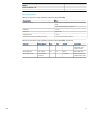
Table 4. Input/output overview
Standard
configuration
Analog inputs Binary inputs/outputs
CT VT BI BO
A 4 - 4 6
15. Communication
For application specific situations where
communication between IEDs and remote
systems are needed, the 611 series IEDs also
support IEC 61850 and Modbus
®
communication
protocols. Operational information and controls
are available through these protocols. Some
communication functionality, for example,
horizontal communication between the IEDs, is
only enabled by the IEC 61850 communication
protocol.
The IEC 61850 communication implementation
supports monitoring and control functionality.
Additionally, parameter settings and disturbance
and fault records can be accessed using the IEC
61850 protocol. Disturbance records are available
to any Ethernet-based application in the standard
COMTRADE file format. The IED supports
simultaneous event reporting to five different
clients on the station bus.
The IED can send binary signals to other IEDs (so-
called horizontal communication) using the IEC
61850-8-1 GOOSE (Generic Object Oriented
Substation Event) profile. Binary GOOSE
messaging can, for example, be employed for
protection and interlocking-based protection
schemes. The IED meets the GOOSE
performance requirements for tripping
applications in distribution substations, as defined
by the IEC 61850 standard.
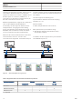
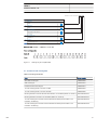
The IED offers an optional second Ethernet bus to
enable the creation of a self-healing Ethernet ring-
type topology. The communication module
including three RJ-45 ports is used when the
whole substation bus is based on CAT5 STP
cabling.
The self-healing Ethernet ring solution enables a
cost-efficient communication loop controlled by a
managed switch with rapid spanning tree protocol
(RSTP) support. The managed switch controls the
consistency of the ring, routes the data and
corrects the data flow in case of a communication
disturbance. The IEDs in the ring topology act as
unmanaged switches forwarding unrelated data
traffic. The self-healing Ethernet ring solution
avoids single point of failure concerns and
improves the reliability of the communication.
All communication connectors, except for the
front port connector, are placed on integrated
Busbar and Multipurpose Differential Protection and Control 1MRS757467 B
REB611
Product version: 1.0
ABB 11

optional communication modules. The IED can be
connected to Ethernet-based communication
systems via the RJ-45 connector (100Base-TX) or
the fibre-optic LC connector (100Base-FX). If
connection to a serial bus is required, the 10-pin
RS-485 screw terminal can be used.
Modbus implementation supports RTU, ASCII and
TCP modes. Besides standard Modbus
functionality, the IED supports retrieval of time-
stamped events, changing the active setting
group and uploading of the latest fault records. If
a Modbus TCP connection is used, five clients
can be connected to the IED simultaneously.
When the IED uses the RS-485 bus for the serial
communication, both two- and four-wire
connections are supported. Termination and pull-
up/down resistors can be configured with jumpers
on the communication card. External resistors are
not needed.
The IED supports the following time
synchronization methods with a time-stamping
resolution of 1 ms:
Ethernet-based:
• SNTP (Simple Network Time Protocol)
With special time synchronization wiring:
• IRIG-B (Inter-Range Instrumentation Group -
Time Code Format B)
In addition, the IED supports time synchronization
via the Modbus protocol.
Managed Ethernet switch
with RSTP support
Managed Ethernet switch
with RSTP support
Network
Network
REF611
Overcurrent
Earth-fault
Phase unbalance
Thermal overload
AR sequence in progress
Disturb.rec.trigged
Trip circuit failure
Breaker failure
REF611
Overcurrent
Earth-fault
Phase unbalance
Thermal overload
AR sequence in progress
Disturb.rec.trigged
Trip circuit failure
Breaker failure
REF611
Overcurrent
Earth-fault
Phase unbalance
Thermal overload
AR sequence in progress
Disturb.rec.trigged
Trip circuit failure
Breaker failure
REM611
Short circuit
Combined protection
Thermal overload
Motor restart inhibit
Emergency start enabled
Disturb.rec.trigged
Supervision alarm
Breaker failure
REB611
High-impedance 1 operate
High-impedance 2 operate
High-impedance 3 operate
High-impedance start
Segregated supervision
Disturb.rec.trigged
Trip circuit failure
Breaker failure
REF611
REF611
REF611
REM611
REB611
Client B
Client A
GUID-A19C6CFB-EEFD-4FB2-9671-E4C4137550A1 V1 EN
Figure 6. Self-healing Ethernet ring solution
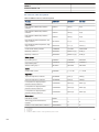
Table 5. Supported station communication interfaces and protocols
Interfaces/protocols
Ethernet Serial
100BASE-FX 10/100BASE-TX RS-485
IEC 61850 ● ● -
MODBUS RTU/ASCII - - ●
MODBUS TCP/IP ● ● -
● = Supported
Busbar and Multipurpose Differential Protection and Control 1MRS757467 B
REB611
Product version: 1.0
12 ABB

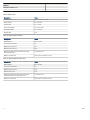
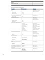
16. Technical data
Table 6. Dimensions
Description Value
Width Frame 177 mm
Case 164 mm
Height Frame 177 mm (4U)
Case 160 mm
Depth 201 mm (153 + 48 mm)
Weight Complete IED 4.1 kg
Plug-in unit only 2.1 kg
Table 7. Power supply
Description Type 1 Type 2
U
aux
nominal 100, 110, 120, 220, 240 V AC
50 and 60 Hz
24, 30, 48, 60 V DC
48, 60, 110, 125, 220, 250 V DC
Maximum interruption time in the
auxiliary DC voltage without
resetting the IED
50 ms at U
n
rated
U
aux
variation 38...110% of U
n
(38...264 V AC) 50...120% of U
n
(12...72 V DC)
80...120% of U
n
(38.4...300 V DC)
Start-up threshold 19.2 V DC (24 V DC * 80%)
Burden of auxiliary voltage supply
under quiescent (P
q
)/ operating
condition
DC < 12.0 W (nominal)/< 18.0 W (max.)
AC < 16.0 W (nominal)/< 21.0 W (max.)
DC < 12.0 W (nominal)/< 18.0 W (max.)
Ripple in the DC auxiliary voltage Maximum 15% of the DC value (at frequency of 100 Hz)
Fuse type T4A/250 V
Table 8. Energizing inputs
Description
Value
Rated frequency 50/60 Hz
Current inputs Rated current, I
n
0.2/1 A
1)
1/5 A
2)
Thermal withstand capability:
• Continuously 4 A 20 A
• For 1 s 100 A 500 A
Dynamic current withstand:
• Half-wave value 250 A 1250 A
Input impedance < 100 mΩ < 20 mΩ
1) Ordering option for residual current input
2) Residual current and/or phase current
Busbar and Multipurpose Differential Protection and Control
1MRS757467 B
REB611
Product version: 1.0
ABB 13

Table 9. Binary inputs
Description Value
Operating range ±20% of the rated voltage
Rated voltage 24...250 V DC
Current drain 1.6...1.9 mA
Power consumption 31.0...570.0 mW
Threshold voltage 18...176 V DC
Reaction time 3 ms
Table 10. Signal output X100: SO1
Description Value
Rated voltage 250 V AC/DC
Continuous contact carry 5 A
Make and carry for 3.0 s 15 A
Make and carry for 0.5 s 30 A
Breaking capacity when the control-circuit time
constant L/R<40 ms
1 A/0.25 A/0.15 A
Minimum contact load 100 mA at 24 V AC/DC (2.4 VA)
Table 11. Signal outputs and IRF output
Description
Value
Rated voltage 250 V AC/DC
Continuous contact carry 5 A
Make and carry for 3.0 s 10 A
Make and carry 0.5 s 15 A
Breaking capacity when the control-circuit time
constant L/R<40 ms, at 48/110/220 V DC
1 A/0.25 A/0.15 A
Minimum contact load 100 mA at 24 V AC/DC (2.4 VA)
Busbar and Multipurpose Differential Protection and Control 1MRS757467 B
REB611
Product version: 1.0
14 ABB

Table 12. Double-pole power output relays with TCS function
Description Value
Rated voltage 250 V AC/DC
Continuous contact carry 8 A
Make and carry for 3.0 s 15 A
Make and carry for 0.5 s 30 A
Breaking capacity when the control-circuit time
constant L/R<40 ms, at 48/110/220 V DC (two
contacts connected in series)
5 A/3 A/1 A
Minimum contact load 100 mA at 24 V AC/DC (2.4 VA)
Trip-circuit supervision (TCS):
• Control voltage range 20...250 V AC/DC
• Current drain through the supervision circuit ~1.5 mA
• Minimum voltage over the TCS contact 20 V AC/DC (15...20 V)
Table 13. Single-pole power output relays
Description Value
Rated voltage 250 V AC/DC
Continuous contact carry 5 A
Make and carry for 3.0 s 15 A
Make and carry for 0.5 s 30 A
Breaking capacity when the control-circuit time
constant L/R<40 ms, at 48/110/220 V DC
1 A / 0.25 A / 0.15 A
Minimum contact load 100 mA at 24 V AC/DC (2.4 VA)
Table 14. Front port Ethernet interfaces
Ethernet interface
Protocol Cable Data transfer rate
Front TCP/IP protocol Standard Ethernet CAT 5 cable with RJ-45 connector 10 MBits/s
Table 15. Station communication link, fibre-optic
Connector
Fibre type
1)
Wave length Max. distance
Permitted path attenuation
2)
LC MM 62.5/125 μm glass
fibre core
1300 nm 2 km < 8 dB
1) (MM) multi-mode fibre, (SM) single-mode fibre
2) Maximum allowed attenuation caused by connectors and cable together
Busbar and Multipurpose Differential Protection and Control
1MRS757467 B
REB611
Product version: 1.0
ABB 15

Table 16. IRIG-B
Description Value
IRIG time code format
B004, B005
1)
Isolation 500 V 1 min
Modulation Unmodulated
Logic level TTL Level
Current consumption 2...4 mA
Power consumption 10...20 mW
1) According to 200-04 IRIG -standard
Table 17. Degree of protection of flush-mounted IED
Description Value
Front side IP 54
Rear side, connection terminals IP 20
Table 18. Environmental conditions
Description
Value
Operating temperature range -25...+55ºC (continuous)
Short-time service temperature range
-40...+85ºC (< 16 h)
1)2)
Relative humidity < 93%, non-condensing
Atmospheric pressure 86...106 kPa
Altitude Up to 2000 m
Transport and storage temperature range -40...+85ºC
1) Degradation in MTBF and HMI performance outside the temperature range of -25...+55ºC
2) For IEDs with an LC communication interface the maximum operating temperature is +70ºC
Table 19. Environmental tests
Description
Type test value Reference
Dry heat test (humidity < 50%) • 96 h at +55ºC
• 16 h at +85ºC
IEC 60068-2-2
Cold test • 96 h at -25ºC
• 16 h at -40ºC
IEC 60068-2-1
Change of temperature test • 5 cycles (3 h + 3 h) at
25°C…+55°C
IEC 60068-2-14
Damp heat test, cyclic • 6 cycles (12 h + 12 h) at
+25°C…+55°C, humidity > 93%
IEC 60068-2-30
Storage test • 96 h at -40ºC
• 96 h at +85ºC
IEC 60068-2-2
IEC 60068-2-1
Busbar and Multipurpose Differential Protection and Control 1MRS757467 B
REB611
Product version: 1.0
16 ABB

Table 20. Electromagnetic compatibility tests
Description Type test value Reference
1 MHz/100 kHz burst disturbance
test:
IEC 61000-4-18
IEC 60255-22-1, class III
IEEE C37.90.1-2002
• Common mode 2.5 kV
• Differential mode 2.5 kV
3/10/30 MHz burst disturbance test: IEC 61000-4-18
• Common mode 2 kV
Electrostatic discharge test: IEC 61000-4-2
IEC 60255-22-2
IEEE C37.90.3-2001
• Contact discharge 8 kV
• Air discharge 15 kV
Radio frequency interference tests:
10 V (rms)
f=150 kHz...80 MHz
IEC 61000-4-6
IEC 60255-22-6, class III
10 V/m (rms)
f=80...2700 MHz
IEC 61000-4-3
IEC 60255-22-3, class III
10 V/m
f=900 MHz
ENV 50204
IEC 60255-22-3, class III
20 V/m (rms)
f=80...1000 MHz
IEEE C37.90.2-2004
Fast transient disturbance tests: IEC 61000-4-4
IEC 60255-22-4
IEEE C37.90.1-2002
• All ports 4 kV
Surge immunity test: IEC 61000-4-5
IEC 60255-22-5
• Communication 2 kV, line-to-earth
• Other ports 4 kV, line-to-earth
2 kV, line-to-line
Power frequency (50 Hz) magnetic
field:
IEC 61000-4-8
• Continuous
• 1...3 s
300 A/m
1000 A/m
Pulse magnetic field immunity test 1000 A/m IEC 61000-4-9
Damped oscillatory magnetic field
immunity test
100 A/m
IEC 61000-4-10
Voltage dips and short interruptions 30%/10 ms
60%/100 ms
60%/1000 ms
> 95%/5000 ms
IEC 61000-4-11
Busbar and Multipurpose Differential Protection and Control 1MRS757467 B
REB611
Product version: 1.0
ABB 17

Table 20. Electromagnetic compatibility tests, continued
Description Type test value Reference
Power frequency immunity test:
• Common mode
• Differential mode
Binary inputs only
300 V rms
150 V rms
IEC 61000-4-16
IEC 60255-22-7, class A
Emission tests: EN 55011, class A
IEC 60255-25
• Conducted
0.15...0.50 MHz < 79 dB (µV) quasi peak
< 66 dB (µV) average
0.5...30 MHz < 73 dB (µV) quasi peak
< 60 dB (µV) average
• Radiated
30...230 MHz < 40 dB (µV/m) quasi peak, measured
at 10 m distance
230...1000 MHz < 47 dB (µV/m) quasi peak, measured
at 10 m distance
Table 21. Insulation tests
Description
Type test value Reference
Dielectric tests IEC 60255-5 and
IEC 60255-27
• Test voltage 2 kV, 50 Hz, 1 min
500 V, 50 Hz, 1 min, communication
Impulse voltage test IEC 60255-5 and
IEC 60255-27
• Test voltage 5 kV, 1.2/50 μs, 0.5 J
1 kV, 1.2/50 μs, 0.5 J, communication
Insulation resistance measurements IEC 60255-5 and
IEC 60255-27
• Isolation resistance > 100 MΩ, 500 V DC
Protective bonding resistance IEC 60255-27
• Resistance < 0.1 Ω, 4 A, 60 s
Busbar and Multipurpose Differential Protection and Control 1MRS757467 B
REB611
Product version: 1.0
18 ABB

Table 22. Mechanical tests
Description Reference Requirement
Vibration tests (sinusoidal) IEC 60068-2-6 (test Fc)
IEC 60255-21-1
Class 2
Shock and bump test IEC 60068-2-27 (test Ea shock)
IEC 60068-2-29 (test Eb bump)
IEC 60255-21-2
Class 2
Seismic test IEC 60255-21-3 Class 2
Table 23. Product safety
Description Reference
LV directive 2006/95/EC
Standard EN 60255-27 (2005)
EN 60255-1 (2009)
Table 24. EMC compliance
Description Reference
EMC directive 2004/108/EC
Standard EN 50263 (2000)
EN 60255-26 (2007)
Table 25. RoHS compliance
Description
Complies with RoHS directive 2002/95/EC
Busbar and Multipurpose Differential Protection and Control 1MRS757467 B
REB611
Product version: 1.0
ABB 19

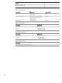
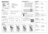
Protection functions
Table 26. High-impedance differential protection (HIPDIF)
Characteristic Value
Operation accuracy Depending on the frequency of the current measured: f
n
±2 Hz
±1.5% of the set value or ±0.002 x In
Start time
1)2)
Minimum Typical Maximum
IFault = 2.0 x set
Start value
12 ms 16 ms 24 ms
IFault= 10 x set Start
value
10 ms 12 ms 14 ms
Reset time < 40 ms
Reset ratio Typical 0.96
Retardation time < 35 ms
Operate time accuracy in definite time mode ±1.0% of the set value or ±20 ms
1) Measurement mode = default (depends on stage), current before fault = 0.0 x In, fn = 50 Hz, fault current with nominal frequency injected from
random phase angle, results based on statistical distribution of 1000 measurements
2) Includes the delay of the signal output contact
Table 27. High-impedance differential protection (HIPDIF) main settings
Parameter
Values (Range) Unit Step Default Description
Operate value 1...200 %In 1 5 Operate value,
percentage of the
nominal current
Minimum operate time 20...300000 ms 10 20 Minimum operate
time
Busbar and Multipurpose Differential Protection and Control 1MRS757467 B
REB611
Product version: 1.0
20 ABB
Page is loading ...
Page is loading ...
Page is loading ...
Page is loading ...
Page is loading ...
Page is loading ...
Page is loading ...
Page is loading ...
Page is loading ...
Page is loading ...
Page is loading ...
Page is loading ...
Page is loading ...
Page is loading ...
Page is loading ...
Page is loading ...
-
 1
1
-
 2
2
-
 3
3
-
 4
4
-
 5
5
-
 6
6
-
 7
7
-
 8
8
-
 9
9
-
 10
10
-
 11
11
-
 12
12
-
 13
13
-
 14
14
-
 15
15
-
 16
16
-
 17
17
-
 18
18
-
 19
19
-
 20
20
-
 21
21
-
 22
22
-
 23
23
-
 24
24
-
 25
25
-
 26
26
-
 27
27
-
 28
28
-
 29
29
-
 30
30
-
 31
31
-
 32
32
-
 33
33
-
 34
34
-
 35
35
-
 36
36


ABB Relion 611 series REB611 User manual
- Category
- Measuring, testing & control
- Type
- User manual
Ask a question and I''ll find the answer in the document
Finding information in a document is now easier with AI
Related papers
-
ABB Relion 611 series REB611 User manual
-
-
-
-
-
-
ABB 620 Series ANSI User manual
-
-
-
Other documents
-
Hager VME01SPD Protection Devices Surge Protection Kit User manual
-
Dwyer Series MCS User manual
-
HP Modular Cooling System Quick start guide
-
 Pilot Communications PMAC202 User manual
-
Siemens UL1066 User manual
-
-
SCANMASKIN SC-450 User manual
-
Dahua IP Villa Door Station User manual
-
 Mikro RX232 User guide
-
Westermo RPW-600 User guide

