Page is loading ...

S-2CB, Manual.doc
Copyright 2015. Vestil Manufacturing Corp. Page 1 of 16
S-2CB-SERIES COUNTER-BALLANCE STACKER
OPERATION AND MAINTENANCE MANUAL
Receiving instructions:
After delivery, IMMEDIATELY remove the packaging from the product in a manner that preserves the
packaging and maintains the orientation of the product in the packaging; then inspect the product closely to
determine whether it sustained damage during transport. If damage is discovered during the inspection,
immediately
record a complete description of the damage on the bill of lading. If the product is
undamaged, discard the packaging.
NOTES
:
1) Complian
ce with laws, regulations, codes, and non-voluntary standards enforced in the location where
the product is used is exclusively the responsibility of the owner/end-user.
2) VESTIL is not liable for any injury or property damage that occurs as a consequence of failing to apply either:
a) Instructions in this manual; or b) Information provided on labels affixed to the product.
Neither is Vestil
responsible for any consequential damages sustained as a result of failing to exercise sound judgment
while assembling, installing, using or maintaining this product.
TABLE OF CONTENTS PAGE TABLE OF FIGURES PAGE
Safety Principles 2
Product Introduction 2
Safety Guidelines 3
Removing EPT from Pallet 3 - 4
Use, 1
st
Inspection, & Functions Tests 6
Operation
6 - 7
Lifting & Transporting Loads
7
Batteries & Charger
7 - 8
Troubleshooting
9 - 13
5
14-15
16
VESTIL MANUFACTURING CORP.
2999 North Wayne Street, P.O. Box 507, Angola, IN 46703
Telephone: (260) 665-7586 -or- Toll Free (800) 348-0868
Fax: (260) 665-1339
www.vestilmfg.com e-mail: [email protected]m
FIG. 5 Function Controls, Gauges, & Safety Features
Maintenance & Inspections
Markings

S-2CB, Manual.doc
Copyright 2015 Vestil Manufacturing Corp.
Page 2 of 16
PRODUCT INTRODUCTION
Specifications appear in the table below:
Vestil Manufacturing Corp. created this manual to acquaint owners and users of our electric pallet trucks
with safe operation and maintenance procedures. Employers are responsible for instructing employees to
use the product properly. Employees and any other persons, who might foreseeably use, repair, or
perform maintenance on the EPT must read and understand every instruction BEFORE using the device.
Cart operators should have access to the manual at all times and should review the directions before each
use. Contact Vestil for answers to any question you have after reading the entire manual.
Although Vestil diligently strives to identify foreseeable hazardous situations, th
is manual cannot address
every conceivable danger. The end-user is ultimately responsible for exercising sound judgment at all times.
SAFETY PRINCIPLES
We offer two types of counter-balance stackers (S-2CB): 2,000 pound (~907kg) capacity models.
Each unit conforms to the generalized specifications disclosed in this manual and fulfills our demanding standards
for quality, safety and durability.
Vestil Manufacturing Corp. recognizes the critical importance of workplace safety. Each person who might
participate in operation or maintenance of the product must read this manual. Read the entire manual and fully
understand the directions BEFORE using or performing maintenance on the cart. If you do not
understand an instruction, contact Vestil for clarification. Failure to adhere to the directions in this
manual might lead to serious personal injury or even death.
Vestil is not liable for any injury or property damage that occurs as a consequence of failing to apply the safe
operation and maintenance procedures explained in this manual or that appear on labels affixed to the product.
Furthermore, failure to exercise good judgment and common sense may result in property damage, serious
personal injury, or death, and also are not the responsibility of Vestil.
This manual applies the hazard identification methods suggested for instruction manuals by the American
National Standards Institute (ANSI). In accordance with ANSI guidelines for hazard identification language, this
manual classifies personal injury risks and situations that could lead to property damage with SIGNAL WORDS.
These signal words announce an associated safety message. The reader must understand that the signal word
chosen indicates the seriousness of that hazard according to the following convention:
Identifies a hazardous situation which, if not avoided, WILL result in DEATH or SERIOUS
INJURY. Use of this signal word is limited to the most extreme situations.
Identifies a hazardous situation which, if not avoided, COULD result in DEATH or
SERIOUS INJURY.
Indicates a hazardous situation which, if not avoided, COULD result in MINOR or
MODERATE injury.
Identifies practices not related to personal injury, such as operation that could damage the cart.
No safety alert symbol (equilateral triangle enclosing an exclamation point) accompanies this
signal word.
Thank you for purchasing Counter Balance Stacker (“S-2CB-118,” “counter-
balance stacker,” “truck,” or “unit”) offered by Vestil Manufacturing Corporation
(“Vestil”). Our counter-balance stackers are durable, high-quality products that
combine safety features and low-maintenance mechanisms. Despite the product’s
relatively simple mechanics, all personnel must familiarize themselves with the safe
operation instructions provided in this manual.

S-2CB, Manual.doc
Copyright 2015 Vestil Manufacturing Corp. Page 3 of 16
SAFETY GUIDELINES
Failure to read and understand the instructions included in this manual before using or servicing the
pallet truck constitutes misuse of the product. Study the entire manual before you use the truck for the
first time and before each subsequent use. Read the manual to refresh your understanding of the safe use and
maintenance procedures on p. 50-51. If questions remain after you finish reading the manual, contact Vestil for
answers. DO NOT attempt to resolve any problem with the truck unless you are certain
that it will be safe to use
afterwards.
To decrease the risk of electrocution:
DO NOT contact or operate the pallet truck close to electrified wires or other sources of electricity;
Before operating theS-2CB, always inspect the area where you will use it.
Improper use might result in serious personal injuries to the operator and/or bystanders. To
minimize the possibility of injury, ALL persons who might operate, perform maintenance on, or service the S-2CB
must read, understand and apply the following instructions:
DO NOT operate the S-2CB unless and until you are:
1. Trained to use the machine; AND
2. Certified as a trained operator by your employer in accordance with U.S. OSHA regulations (29 CFR
§1910.178) and any standards incorporated by reference (e.g. ANSI/ITSDF B56.1-2005).
DO NOT attempt to lift or transport loads that exceed the rated capacity.
Inspect the machine before each use; DO NOT use the EPT unless it is in normal condition. Normal operating
condition exists if the S-2CB passes the inspection and functions tests described under the heading, “Inspect
& Perform a Functions Tests” on p. 14.
DO NOT use the unit until you read and understand the entire owner’s manual. Review the manual before
each use AND before performing maintenance on the device.
DO NOT use the S-2CB if the load-supporting elements sustain any structural damage. Structural elements
include, but are not limited to, the forks, carriage, and wheels. If structural damage is present, immediately
tag the unit “Out of Service” and inform maintenance personnel of the problem.
DO NOT use the S-2CB if it makes unusual noises during operation.
DO NOT allow people to ride on the stacker. Only the operator of S-2CB equipped with a properly
installed rider platform.
DO NOT attempt to lift an unevenly distributed load. Always center and evenly distribute the load on the forks.
DO NOT operate the S-2CB on surfaces (ramps or grades).
DO NOT leave the S-2CB unattended while it supports a load. Always fully lower the forks, and then
completely disengage the skid or pallet.
DO NOT modify the stacker without first receiving written authorization from Vestil. Unauthorized
modifications may make the S-2CB unsafe to use.
To maximize the service life of the S-2CB and to prevent damage:
Always store the machine in a secure, dry location where it will not interfere with traffic or other activities.
Maintain the product as suggested in “Maintenance & Inspections”.
REMOVING THE Coounter-Balance Stacker FROM THE SHIPPING PALLET:
Counter-Balance stacker is s
hipped in ready-to-use condition. However, it must first be removed from the shipping pallet
before it can be used for the first time.
DO NOT attempt to drive the Stacker off of the pallet; it might tip over and cause bodily injuries or
property damage. To minimize the risk of injury to yourself or other persons, perform the following steps to
remove the machine from the shipping pallet:
1. Remove all packing material.
2. Inform all personnel not participating in the unpacking process to clear the area.
3.
Lift the S-2CB off of the pallet using a hoist or a with a capacity of at least 4
,000 pounds. Always
apply the proper hoisting procedures or forklift operation practices you learned during your training program.

S-2CB, Manual.doc
Copyright 2015 Vestil Manufacturing Corp.
Page 4 of 16
Connect the sling to both hook points on the Mas
t (1
on ea
ch side
;
the pictur
e below
only shows the hook point
on the right side); then lift the unit no more than 6 – 8 inches above the pallet. The S-2CB will tilt towards the
control yoke. Additionally, it may swing from side-to-side once free of the pallet if you did not properly position the
hoist above the center of the sling. Stabilize the suspended truck with one hand, and stand safely to the side
while operating the hoist.
To remove the S-2CB from the shipping pallet using a hoist:
Hook Point

S-2CB, Manual.doc
Copyright 2015 Vestil Manufacturing Corp.
Page 5 of 16
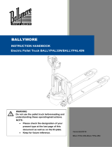
EMERGENCY STOP (“E-STOP”) BUTTON:
Press the E-stop button to
immediately interrupt all powered
functions. Use the E-stop during
operation if the travel or fork (raise
and lower) functions do not respond
normally to operator commands.
Use the E-stop as a service brake to secure the
S-2CB when parked.
FIG. 1: Function Controls, Gauges, and Safety Features
BELLY SWITCH:
The belly switch protects the operator from injury
while driving the EPT in reverse. When pressed, the
truck will change direction, i.e. move forward, for
approximately 3 seconds; after 3 seconds it will stop
completely. If the belly switch becomes jammed or
stuck, the stacker will move forward (away from the
operator) for at most 3 seconds; the control circuit will
remain disabled until reset.
To reset the circuit, either raise the ha
ndle to the
fully vertical position (or simply release the
handle), or press it downwards to the fully
horizontal position.
MOVEMENT CONTROLLERS:
To drive the S-2CB in the
forward direction, rotate the
movement control forward with
your thumbs as indicated by the
solid arrow superimposed on
photograph below. To move the
pallet truck in reverse
, rotate
the control wheel in the opposite
direction, which is shown with a
dashed arrow.
The degree of rotation determines the speed of
movement, so the farther you press the wheel in
either direction, the faster the S-2CB will travel, up to
a maximum speed of ~3.4mph
when unloaded or
~2.8mph when loaded to capacity. Simply by
releasing the movement control, the S-2CB will
decelerate to a complete stop.
BATTERY CHARGE GAUGE:
The battery charge gauge
indicates the status of the battery.
It is located on top of the EPT main
body and to the right of the control
yoke. As the battery discharges,
display lines disappear from right
to left.
A
lways check the gauge before
using the device; make sure that
the battery is charged before using
the
p
allet truck.
Reverse Forward
slow/fast speed switch
Handle
Raise Forks
Lower Forks
Movement Controllers
("Butterfly" Switches)
Belly Switch
(Emergency Stop)

S-2CB, Manual.doc
Copyright 2015 Vestil Manufacturing Corp.
Page 6 of 16
USE INSTRUCTIONS:
1.
Determine Condition of Floor or Other Supporting Surface: Inspect the floor or other surfaces prior to use.
The supporting surface must be smooth and dry so choose a route that avoids obstacles, spills, and surface
damage.
Casters might become stuck in gaps or cracks in the surface, which could cause the S-2CB to
stop suddenly. A sudden stop can cause the load to shift and the load and truck might tip over.
2. Inspect the S-2CB & Perform a Functions Test:
Inspection Prior to Use:
ALWAYS inspect the unit before you use it.
Begin the inspection by removing all debris found on the surface of
the forks and the housing, and then:
a. Check the forks for deformation and cracks;
b.
Check the floor beneath the truck and the truck itself for leaked hydraulic fluid or battery acid.
DO NOT use the S-2CB if you discover any damage or abnormalities. Tag the unit “Out-of-
Service” and report the problem[s] to authorized maintenance personnel.
Functions Test:
Verify that the unit works properly. Drive the stacker to a location where the following tests can be performed
without contacting overhead obstructions or items on the ground:
1. Raise the forks to the maximum elevation;
2. Return the forks to the lowest position.
3.
Raise the forks, and while raising them, press the E-stop button. The forks should immediately stop
moving. Reset the E-stop by returning the control yoke to either position 1 or 3 (see Operation Step 3
below on this page), and then pull up on the red button.
4. Fully raise the forks, and while lowering the forks press the E-stop. The forks should immediately stop
moving. Reset the E-stop.
5.
Drive the S-2CB in reverse at low speed and while driving press the belly switch. The machine should
immediately move in the opposite direction for ~3 seconds and then stop. Reset the control yoke.
6.
Drive the S-2CB in both the forward and reverse directions for a few seconds.
7.
Test the horn (see Fig. 1, p. 5).
8. Verify that the control yoke automatically returns to the vertical position when released (see Operation
Step 3 on this page).
Only use the pallet truck if all mechanisms function normally. If [a] malfunctions occurred, park the
stacker in a safe location, tag it “Out-of-Service” and then report the malfunctions to maintenance personnel.
Operation:
Step 1: Turn on the power.
Step 2
: Pull the red E-Stop button up to disengage the service brake.
Step 3
: Tilt the control yoke to the drive position (#2), which is shown
in the photograph to the right.
NOTE: The S-2CB uses magnetic brakes, which engage when
the handle is in or near either of the neutral positions (1 and 3).
The yoke is designed to automatically return to neutral position #1 after
the handle is released; therefore, the brakes will engage automatically
as well.
Step 4: Rotate the movement control wheel in the appropriate direction to move either
forward or in reverse.
1 = Neutral
2 = Drive
3 = Neutral

S-2CB, Manual.doc
Copyright 2015 Vestil Manufacturing Corp.
Page 7 of 16
Step 5: Drive the stacker to the desired location.
To steer the unit, turn the yoke to the right
or left of
the center line. Moving the yoke to the right will
cause the S-2CB to turn to the right, and moving
the yoke to the left of the center line will cause the
unit to turn left. The degree of deflection from the
centerline determines how sharply the S-2CB
turns. The illustration at right demonstrates how
the position of the yoke determines the direction
the machine follows.
Lifting and Transporting Loads
:
DO NOT operate the S-2Cb until you read AND understand every instruction. If you do not understand
an instruction, contact Vestil for clarification. To reduce the possibility of sustaining or causing serious personal
injuries, ALWAYS:
1. Make sure that all other persons clear the area while you use the S-2CB.
2. Apply the fork truck operation and lifting practices learned during your operator training, and applied by your
employer. Follow the instructions below ONLY to the extent that they do not disagree with the operating practices
required by your employer.
Make sure that the net weight to be lifted (load + skid) does not exceed the rated load (capacity) of your truck;
Center and evenly distribute the load on the forks. The load must not project more than 2” beyond the tips of the forks.
3. Review the safety guidelines on p. 3 before each use:
Apply proper loading techniques ;
Ask a coworker to help you load and unload the lifter.
4. “Operator” means a person, who is trained and authorized to use a manually propelled high lift device. ONLY
persons who have successfully completed a training program, like the courses outlined on p. 4-5 of
B56.10-2006, should operate the S-2CB. Safe operation requires operators to:
Develop safe working habits and a process for identifying hazards that exist or might be encountered during
operation;
Conduct thorough inspections of the usage area to identify unusual/hazardous conditions. Walk the path you will
use to transport loads with the lifter beforehand. Do not use the S-2CB lift if the floor (or other supporting
surface) is uneven or damaged or cannot support the combined weight of the operator, the lifter and the load.
Make sure that the lifter has been inspected as recommended in the “Inspections & Maintenance” section of this
manual (p. 19). Use the lifter ONLY IF it is deemed safe to use by designated inspection personnel.
To engage a pallet/skid, drive the unit to a position in front of the intended load. Before engaging the load, confirm
that the forks will fit within the fork pockets. Fully lower the forks to allow them to slide into the fork pockets of the
skid. Confirm that the net weight of the load plus the skid do not exceed the capacity of the S-2CB.
Continue forward until either the skid rests against the back
(vertical/upri
ght portion), or the forks are as far
underneath the skid as they can be. When the skid contacts the back of the forks, put the yoke in a neutral position to
stop forward motion. Wait until the stacker stops completely, and then lift the skid off of the ground/supporting
surface by pressing one of the two fork raising buttons.
Proper Transport Configuration: To avoid unintend
ed contact between the skid/pallet and surface features, transport
the load to the desired location with the forks elevated.
To release the load, stop in the desired location; fully lower the forks; and then slowly drive the S-2CB forward until
the forks are no longer beneath the skid/pallet.
Batteries and Charger
:
The charger allows electrical current to flow from
a wall socket through the batteries. While operating the
charger, contact with water (rain, sno
w, etc.) could result in
electric shock or electrocution. Do NOT recharge the batteries
if the S-2CB is outdoors. Only recharge the batteries indoors.
Turn off your S-2CB:
Push E-stop to turn off the S-2CB
Plug the charger’s AC cord into an 115VAC power source:
The AC cord is tucked inside the battery box on the left side
Press E-Stop

S-2CB, Manual.doc
Copyright 2015 Vestil Manufacturing Corp.
Page 8 of 16
A proper storage location is one where the unused lifter will not:
1.
Interfere with or obstruct traffic or other operations;
2.
Be exposed to corrosive chemicals or water, either as a consequence of weather or of worksite
conditions.

S-2CB, Manual.doc
Copyright 2015 Vestil Manufacturing Corp. Page 9 of 16
T
ROUBLESHOOTING:
Before performing any corrective action described in the following table, block the drive
wheel off of the ground.
Contact Vestil for problems at time of installation, or for any problems not addressed below.
Problem: Possible cause(s): Action:
Unit does not respond to
movement controls (does not
move either forward or in
reverse).
Battery voltage low (battery
charge lower than 17 Volts)
Problem with motor controller
(check for LED flash code on
side of controller)
Fuse blown
Charge batteries.
Bad batteries; load test batteries
and replace if necessary.
Consult diagnostics page Table 2
Troubleshooting Chart; or Refer
to 15-124-029 electrical drawing
for proper voltage readings and
operation; or Consult Factory
Remove back shroud and check
fuses (3 fuses).
Unit will not charge Charger malfunction
Bad batteries
Verify output voltage on charger,
it should be 26 to 30 volts, dc,
connected to batteries, and
plugged into 115vac.
Load test the batteries
Unit will not go forward; reverse
works; belly switch just kills unit
(does not go forward and faults
out)
Broken wire, or loose connection
Contactor bad, motor controller
bad
Locate Pin 2 on Molex connector
at motor controller. Trace wiring
to contactor and verify
connection.
While attempting to go forward,
tap on the contactor with a
screwdriver handle. If the unit
moves forward, then the
contactor may need replaced, or
plungers lubed with a light oil.
Remove both wires from each
side of the contactor, and check
with ohm meter; resistance
should be approximately 38
ohms. If it’s open or zero, the
contactor should be replaced.
Consult diagnostics page Table 2
Troubleshooting Chart; or Refer
to 15-124-029 electrical drawing
for proper voltage readings and
operation; or Consult Factory.
Unit will not go reverse; belly
switch works (i.e. when the
handle is in operating range and
rotating throttle in reverse and
the belly switch is hit, the unit
moves forward and times out)
Broken wire, or loose connection,
contactor bad, motor controller
bad
Same as above; except locate
Pin 3 on Molex connector on
motor controller…and follow
procedure.

S-2CB, Manual.doc
Copyright 2015 Vestil Manufacturing Corp. Page 10 of 16
Problem:
Possible cause(s): Action:
Unit will not go forward, or
reverse.
Broken wire, or loose connection,
bad motor controller.
Throttle assembly bad
Locate Pin 6 on Molex connector
at the motor controller. Try to
drive the unit in forward, there
should be 0 to 5 volts (5V is full
throttle) at this pin. If there is
voltage at pin 5, and 24 volts on
either pin 11, or 12 and the unit
does not move, the motor
controller may be bad. Consult
diagnostics page Table 2
Troubleshooting Chart; or Refer
to 15-124-029 electrical drawing
for proper voltage readings and
operation; or Consult Factory.
If the connections are all good,
and there is no voltage coming
out of throttle assembly, then the
throttle assembly may be bad.
Verify there is 24 volts going into
the throttle assembly, and that
there is a good ground. If there
is still no output voltage for pin 6,
or forward and reverse outputs
replace throttle assembly.
Consult diagnostics page Table 2
Troubleshooting Chart; or Refer
to 15-124-029 electrical drawing
for proper voltage readings and
operation; or Consult Factory
Unit will not move forward, or
reverse, and the Belly switch will
not function, unit does turn on as
indicated by the battery gage
lighting up.
Blown fuse
Broken wire, or loose connection
Verify fuses are good, replace if
blown.
Locate Pin 7 on Molex connector
at the motor controller. Trace
wire back up to tiller head and
verify continuity all the way to the
throttle assembly. Repair any
loose connections.
When replacing throttles, it may
be necessary, and does not hurt
to run a jumper wire from pin 7 to
B-.
Check the ground wire that
comes off of “B-“ on the motor
controller. Re-terminate with a
ring terminal if loose.
Run jumper wire around large
diode coming off of small AGC
fuse. If this diode is bad it can
cause the unit to not move.

S-2CB, Manual.doc
Copyright 2015 Vestil Manufacturing Corp. Page 11 of 16
Problem: Possible cause(s): Action:
Unit will not go forward; the belly
switch functions; reverse works.
Broken wire, or loose connection,
bad motor controller
Bad throttle assembly
Locate Pin 11 on Molex
connector at the motor controller.
Try to drive the unit in forward,
there should be 24 volts at this
pin. If there is voltage and the
unit does not move, the motor
controller may be bad. If there is
no voltage, trace the wiring back
towards the tiller head and check
voltage on each side of
connectors. Continue this until
bad connection is found.
If the connections are all good,
and there is no voltage coming
out of throttle assembly, then the
throttle assembly may be bad.
Verify there is 24 volts going into
the assembly, and that there is a
good ground. If there is still no
output voltage for pin 11, replace
throttle assembly. Reference 15-
124-029.
Belly switch does not function;
forward ok; reverse ok
Broken wire, or loose connection,
bad motor controller
Bad belly switch
Locate Pin 13 on Molex
connector at the motor controller.
Try to drive the unit in reverse,
and hit the belly switch… there
should be 24 volts at this pin. If
there is voltage and the unit does
not move, the motor controller
may be bad. If there is no
voltage, trace the wiring back
towards the tiller head and check
voltage, or continuity on each
side of connectors. Continue this
until bad connection is found.
If the connections are all good,
and there is no voltage, then the
switch may be bad. Verify there
is 24 volts going into the switch;
and check to see if it is coming
back out of the switch when
depressed. If there is no output
voltage, replace the switch.
Unit will not move at all. Stuck Switch The belly switch is stuck on. Tap
the orange belly switch assembly
to see if the switch can be freed.
If this doesn’t work, disassemble
the tiller head by removing 3
screws from bottom. Slightly
loosen up the two screws that
hold the switch in place, this may
free the switch. If it is still stuck,
contact the factory for a
replacement switch.

S-2CB, Manual.doc
Copyright 2015 Vestil Manufacturing Corp. Page 12 of 16
Problem:
Possible cause(s): Action:
Unit will not raise; motor does not
run
Loose wire
Bad solenoid
Upper limit switch out of
adjustment
Blown fuse
Verify 24 volts at coil when raise
is pushed, if no voltage, trace
wiring back to till her head
looking for voltage on each side
of the connectors until the bad
connection is found.
If voltage is present at the
solenoid and the unit does not
raise, remove the two wires to
the coil and measure the coil
resistance. It should be around
19 ohms. If it’s open, or shorted
replace the solenoid.
Bypass upper limit switch and
see if the unit raises…DO NOT
TAKE IT ALL THE WAY UP… If
it does raise, verify the limit
switch is normally closed and will
open when activated. If the limit
switch is ok, try to adjust the
switch accordingly so that the
units raise height is
approximately 7 to 8”
Check fuses.
Unit will not raise; motor runs Lower solenoid stuck on Check to see if the lowering
switch is stuck on. If it is, remove
the tiller head via 3 screws on
bottom and replace switch, or tap
on switch to see if it can be freed
up. If the lower switch is not
stuck “on,” the pump could be
bad, consult factory.
Unit will not lower Loose wire; bad coil
Upper limit switch out of
adjustment
Verify 24 volts at coil when lower
is pushed, if no voltage, trace
wiring back to tiller head looking
for voltage on each side of the
connectors until the bad
connection is found.
If voltage is present at the coil
and the unit does not lower,
remove the connector to the coil
and measure the coil resistance.
It should be around 39 ohms. If
it’s open, or shorted replace the
coil.
Loosen hydraulic line at pump to
relieve pressure build up. Re-
adjust limit switch so unit stops at
7 to 8 inches above the ground.
Unit keeps blowing fuses when
the raise button is pressed
Shorted solenoid for motor raise Remove the wire to the solenoid
coil on the pump motor.
Measure the resistance, it should
be around 19 ohms. If it is nearly
zero ohms replace the solenoid.

S-2CB, Manual.doc
Copyright 2015 Vestil Manufacturing Corp. Page 13 of 16
Problem: Possible cause(s): Action:
Unit will not reverse; belly switch
does not function; forward ok
Broken wire, or loose connection,
bad throttle assembly, bad motor
controller.
Locate Pin 12 on Molex
connector at the motor controller.
Try to drive the unit in reverse,
there should be 24 volts at this
pin. If there is voltage and the
unit does not move, the motor
controller may be bad, consult
factory. If there is no voltage,
trace the wiring back towards the
tiller head and check voltage on
each side of connectors.
Continue this until bad
connection is found. If the
connections are all good, and
there is no voltage coming out of
throttle assembly, then the
throttle assembly may be bad.
Verify there is 24 volts going into
the assembly, and that there is a
good ground. If there is still no
output voltage for pin 12, replace
throttle assembly. Reference 15-
124-029.

S-2CB, Manual.doc
Copyright 2015 Vestil Manufacturing Corp.
Page 14 of 16
Maintenance and Inspections:
According to ANSI B56.1, the counter-balance truck is a “motorized hand truck” (MHT). For this type of lift truck,
only trained, authorized persons should perform inspections or maintenance.
Inspections: ALWAYS review the following warning messages and procedures BEFORE inspecting the MHT.
DO NOT use the pallet truck if an inspection reveals structural damage. Structural damage
includes, but is not limited to, cracked welds, warping or other deformation of the cylinder brackets, forks, front rollers
and wheel(s), handle, or the housing that protects the electrical components.
If an inspection exposes any problem, restore the MHT to normal operating condition BEFORE returning it to
regular service. The MHT must not be used until all repairs have been completed.
According to B56.1-2005:
A “User” is “a person or organization responsible for employing powered industrial trucks.” Therefore, the person
or business that owns the MHT is a user.
“Authorized” means any person designated by the user to operate or maintain the equipment. In other words, the
owner, most likely your employer, is responsible for training and selecting people to inspect and maintain the MHT.
NOTE: A user may choose to contract with a person or an organization for maintenance services. Vestil is not
responsible for the actions of independently contracted maintenance service providers.
DO NOT use brake fluid or jack oil in the hydraulic system. If oil is needed, use an anti-wear hydraulic oil,
viscosity grade 150 SUS at 100°F, (ISO 32 @ 40°C), or a non-synthetic transmission fluid.
Only use replacement parts either supplied or approved by the manufacturer.
The person(s) authorized by the end
-user to inspect the MHT must do so before
it is used for the first time, and
before each subsequent use
. If the MHT is rarely used, inspect the unit at least once per month, or before each use,
whichever is more frequent. Before the inspection, a) disconnect the battery, and b) either chock the wheels or lift the
MHT until the drive wheels no longer contact the ground.
Inspect the pallet truck prior to each use. Specifically look for:
1. Frayed
wires;
2. Oil leaks;
3. Pinched or damaged hoses;
4. Structural damage: cracked welds, warping or other deformation of the cylinder brackets, forks, front rollers
or drive wheel(s), handle, or the housing that protects the electrical components;
5. Proper function of all limit switches;
6. Proper horn operation;
7.
Normal battery condition: clean, not leaking electrolyte solution, secure connections with both terminals.
Also make sure that the battery is immobilized so that it cannot move during operation.
8. Proper rotation of all wheels.
Inspect the MHT each month:
1. Oil level: raise the forks to the maximum height; when the cylinder(s) are properly filled, the oil level should
be 1-1/2 to 2 inches below the reservoir fill hole. Return the forks to the fully lowered position.
2.
Damage to or excessive wear of:
a. Pivot points;
b. Hydraulic h
oses;
c. Elec
tric wires;
d. Retaining rings for the rollers, drive wheels, and all pivot points;
e.
Bearings
3. Wobblines
s or
looseness of rollers and/or drive wheel
s;
4.
Proper function of the hand or foot actuated mechanisms;
5. Proper battery water level;
6. Unusual noise or abnormal movement during operation;
7.
Legibility and undamaged condition of all product labels.
Maintenance: the end-user
must implement a scheduled maintenance program to ensure the proper function and
safety of the lifter. Pages 12-13 of ANSI/ITSDF standard B56.1-2005 describe some recommended maintenance
procedures, and the following steps should be utilized in conjunction with those recommendations.
The user is responsible for training persons to work on the MHT. “Work on” refers to operating,
loading, cleaning, servicing, maintaining, or repairing the product. ONLY trained, authorized maintenance personnel
or independent contractors chosen by the user should perform inspection, maintenance, or repair work.

S-2CB, Manual.doc
Copyright 2015 Vestil Manufacturing Corp. Page 15 of 16
Step 1
: Tag the MHT, “Out of Service.”
Step 2
: Complete an every use and a monthly inspection. If deformity, corrosion, rusting, or excessive wear of
structural members is present, DO NOT use the MHT. Contact Vestil for instructions.
Step
3
: Remove any dirt or other matter from the forks and other surfaces.
Step 4
: Perform all other necessary adjustments and/or repairs, but DO NOT modify the truck.
The reader should understand the significant difference between necessary adjustments and
repairs, and modifications.
An adjustment is a simple correction that restores the MHT to normal operating condition, such as tightening loose
fasteners, or removing dirt or other debris from the surface; a repair refers to replacing worn parts with new or
replacement parts.
DO NOT use the truck if adjustments and/or repairs are incomplete! Return it to service ONLY after finishing all
necessary repairs and adjustments.
A modification is a change that alters the MHT from normal operating condition, like bending the structural members
or removing a part or several parts. NEVER modify the unit without the express, written approval of Vestil.
Modifications may render the product unsafe to use.
Step 5: Make a dated record of the repairs, adjustments and/or replacements made.

S-2CB, Manual.doc
Copyright 2015 Vestil Manufacturing Corp. Page 16 of 16
M
ARKINGS:
Only use the lifter if ALL labels are readable and undamaged. Contact Vestil for replacement labels if necessary,
and DO NOT use the pallet truck until all replacement labels are affixed to the device.
Proper label placement is shown below:
Label #295
Label #220
Label #208
Label #206
Label #527
/