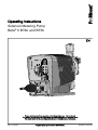
ProMinent Beta b BT4b 1000 Operating Instructions Manual
- Type
- Operating Instructions Manual

Solenoid Metering Pump
Beta
®
b BT4b and BT5b
Operating instructions
EN
Original operating instructions (2006/42/EC)Part no. 986356 BA BE 033 08/18 EN
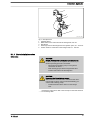
Please carefully read these operating instructions before use. · Do not discard.
The operator shall be liable for any damage caused by installation or operating errors.
The latest version of the operating instructions are available on our homepage.

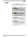
Read the following supplementary information in its entirety! You will ben‐
efit more from using the operating instructions should you already know
this information.
The following are highlighted separately in the document:
n Enumerated lists
Instructions
ð
Outcome of the instructions
Ä ‘State the identity code and serial number’ on page 2
: Links to points
in this chapter
- refer to ... : References to points in this document or another document
[Keys]
Information
This provides important information relating to the cor‐
rect operation of the unit or is intended to make your
work easier.
Safety Information
Safety information is identified by pictograms - see Safety Chapter.
These operating instructions conform to current EU regulations applicable
at the time of publication.
Please state identity code and serial number, which you can find on the
nameplate when you contact us or order spare parts. This enables us to
clearly identify the unit type and material versions.
Supplementary information
Fig. 1: Please read!
Validity
State the identity code and serial number
Supplemental directives
2

Table of contents
1
Identity code.................................................................................... 5
2 About this pump............................................................................... 7
3 Safety Chapter................................................................................. 8
4 Storage, Transport and Unpacking................................................ 13
5 Overview of Equipment and Control Elements.............................. 14
5.1 Overview of Equipment......................................................... 14
5.2 Control Elements................................................................... 15
5.2.1 Pulse control switch........................................................... 15
5.2.2 Stroke Length Adjustment Button...................................... 15
5.2.3 Multifunctional Switch......................................................... 15
5.2.4 Functional and Fault Indicators.......................................... 16
5.2.5 "External control" terminal.................................................. 16
5.2.6 "Level switch" terminal....................................................... 16
6 Functional description.................................................................... 17
6.1 Liquid End............................................................................. 17
6.2 Drive Unit.............................................................................. 17
6.3 Capacity................................................................................ 17
6.4 Self-Bleeding......................................................................... 17
6.5 Operating modes .................................................................. 17
6.6 Functions............................................................................... 18
6.7 Relay..................................................................................... 18
6.8 Hierarchy of Operating Modes, Functions and Fault Sta‐
tuses......................................................................................
18
7 Assembly....................................................................................... 19
8 Installation, hydraulic..................................................................... 20
8.1 Installing hose lines............................................................... 21
8.1.1 Installation of metering pumps without bleed valve............ 21
8.1.2 Installation of metering pumps with bleed valve................. 23
8.1.3 Installation of metering pumps with self-bleeding (SEK
type)................................................................................... 24
8.1.4 Basic installation notes....................................................... 25
9 Electrical installation...................................................................... 27
9.1 Supply voltage connector...................................................... 28
9.1.1 Mains voltage..................................................................... 28
9.2 Supply voltage connector - low voltage................................. 29
9.3 Description of the Terminals................................................. 29
9.3.1 "External control" terminal.................................................. 29
9.3.2 "Level switch" terminal....................................................... 31
9.4 Relay..................................................................................... 31
9.4.1 Relay functions................................................................... 31
9.4.2 "Fault indicating relay" output (identity code 1 + 3)............ 32
9.4.3 "Fault indicating relay" + "Pacing relay" output (identity
code 4 + 5).........................................................................
33
10 Start up.......................................................................................... 34
11 Operation....................................................................................... 37
11.1 Manual................................................................................ 37
11.1.1 Capacity........................................................................... 37
11.1.2 Functions.......................................................................... 37
11.1.3 External contact............................................................... 38
11.1.4 External analogue............................................................ 39
11.2 Remote operation................................................................ 39
12 Maintenance.................................................................................. 40
Table of contents
3

13 Repairs.......................................................................................... 42
13.1 Cleaning valves................................................................... 43
13.2 Replacing the diaphragm.................................................... 45
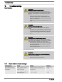
14 Troubleshooting............................................................................. 48
14.1 Faults without a fault message............................................ 48
14.2 Fault messages................................................................... 49
14.3 Warning messages............................................................. 49
14.4 All other faults..................................................................... 49
15 Decommissioning and disposal..................................................... 50
15.1 Decommissioning................................................................ 50
15.2 Disposal.............................................................................. 51
16 Technical data............................................................................... 52
16.1 Performance data................................................................ 52
16.2 Accuracy............................................................................. 54
16.2.1 Standard Liquid End......................................................... 54
16.2.2 Self-Bleeding Liquid End.................................................. 54
16.3 Viscosity.............................................................................. 54
16.4 Material specifications......................................................... 55
16.5 Electrical data...................................................................... 55
16.6 Temperatures...................................................................... 57
16.7 Climate................................................................................ 57
16.8 Degree of Protection and Safety Requirements.................. 58
16.9 Compatibility........................................................................ 58
16.10 Sound pressure level........................................................ 58
16.11 Shipping weight................................................................. 58
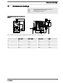
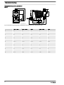
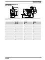
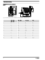
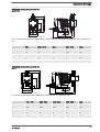
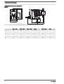
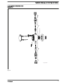
17 Dimensional drawings................................................................... 59
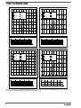
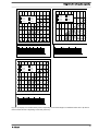
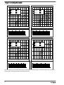
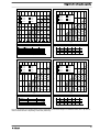
18
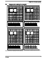
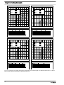
Diagrams for setting the capacity.................................................. 65
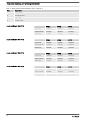
19 Exploded drawings and ordering information................................ 71
19.1 Exploded drawings.............................................................. 71
19.2 Ordering information......................................................... 116
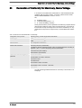
20 Declaration of Conformity for Machinery, Mains Voltage............ 117
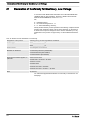
21 Declaration of Conformity for Machinery, Low Voltage............... 118
22 Approvals..................................................................................... 119
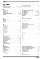
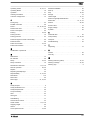
23 Index............................................................................................ 120
Table of contents
4

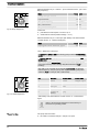
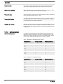
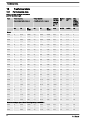
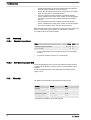
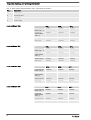
1 Identity code
Product range Beta b
BT4b Type Capacity
bar l/h
1000 10 0.74
1601 16 1.10
1602 16 2.20
1604 16 3.60
0708 7 7.10
0413 4 12.30
0220 2 19.00
BT5b
2504 25 2.90
1008 10 6.80
0713 7 11.00
0420 4 17.10
0232 2 32.00
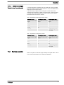
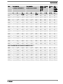
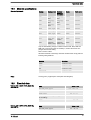
Material of dosing head/valves
PP Polypropylene/PVDF. With the self-bleeding design (SEK): polypropylene/polypropylene
NP Clear acrylic/PVDF. With the self-bleeding design (SEK): Clear acrylic/PVC
PV PVDF/PVDF
TT PTFE + 25 % carbon /PTFE + 25 %
SS Stainless steel 1.4401/1.4571
Material of seals/diaphragm
T PTFE/PTFE-coated
E EPDM/PTFE-coated, only for PP and NP self-bleeding (SEK)
B FPM-B/PTFE-coated, only for PP and NP self-bleeding (SEK)
S Diaphragm with additional FPM coating for media containing silicate
F FDA-compliant
Dosing head design
0 without bleed valve, without valve spring only for NP, TT, SS and type 0232
1 without bleed valve, with valve spring only for NP, TT, SS and type 0232
2 with bleed valve, without valve spring only for PP, PV, NP not for type 0232
3 with bleed valve, with valve spring only for PP, PV, NP not for type 0232
4 design for higher-viscosity media only for PVT, type 1604, 2504, 0708, 1008, 0413,
0713, 0220, 0420
7 self-bleeding (SER) only for PV/NP, not for types 1000, 1601 and 0232
9 self-bleeding (SEK) only for PP/NP, not for types 1000 and 0232
Hydraulic connector
0 Standard connection in line with technical data
5 Connector for 12/6 hose, discharge side only
Identity code
5

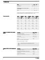
Product range Beta b
9 Connector for 10/4 hose, discharge side only
Design
0 Standard
Logo
0 with ProMinent logo
Electrical connection
U 100 ... 230 V ± 10%, 50/60 Hz*
Cable and plug
A 2 m European
B 2 m Swiss
C 2 m Australian
D 2 m USA
1 2 m open end
Relay
0 no relay
1 fault indicating relay (NC) (change-over relay)
3 fault indicating relay (NO) (change-over relay)
4 as 1 + pacing relay, (ONE each)
5 as 3 + pacing relay, (ONE each)
Accessories
0 no accessories
1 with foot and injection valve, 2 m PVC suction
line, 5 m metering line
Control type
0 no lock
1 with lock: manual operation locked when
external cable plugged in
H External without PCS stop
Control version
0 Standard
A External analogue 0...20 mA / 4...20
mA
Options
00 no options
Identity code
6

2 About this pump
This solenoid metering pump Beta b is equipped with all adjustment and
activation functions for modern water treatment and the dosing of chemi‐
cals. It has pulse step-up and pulse step-down compared with the pre‐
ceding model. This enables it to adapt more precisely to external signal
generators. The result is the simpler and more precise adjustment of
chemical consumption to the actual need. It also has a 10 percent
increase in efficiency and energy efficiency over the preceding model. The
Beta b can be simply adjusted during operation.
Properties of the device
About this pump
7

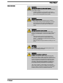
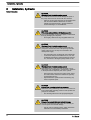
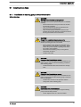
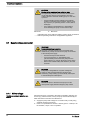
3 Safety Chapter
The following signal words are used in these operating instructions to
denote different severities of danger:
Signal word Meaning
WARNING Denotes a possibly dangerous sit‐
uation. If this is disregarded, you
are in a life-threatening situation
and this can result in serious inju‐
ries.
CAUTION Denotes a possibly dangerous sit‐
uation. If this is disregarded, it
could result in slight or minor inju‐
ries or material damage.
The following warning signs are used in these operating instructions to
denote different types of danger:
Warning signs Type of danger
Warning – automatic start-up.
Warning – high-voltage.
Warning – danger zone.
n Only use the pump to meter liquid feed chemicals.
n Only use the pump after it has been correctly installed and started up
in accordance with the technical data and specifications contained in
the operating instructions.
n Observe the general limitations with regard to viscosity limits, chem‐
ical resistance and density - see also ProMinent resistance list in the
Product Catalogue or at www.prominent.com!
n All other uses or modifications are prohibited.
n The pump is not intended for the metering of gaseous media and
solids.
n The pump is not intended for the metering of flammable media without
implementing suitable protective measures.
n The pump is not intended for the metering of explosive media.
n The pump is not intended for operation in areas at risk from explosion.
n The pump is not intended for exterior applications without the imple‐
mentation of suitable protective measures.
n The pump should only be operated by trained and authorised per‐
sonnel, see the following "Qualifications" table.
n You are obliged to observe the information contained in the operating
instructions at the different phases of the unit's service life.
Identification of safety notes
Warning signs denoting different types of
danger
Intended Use
Safety Chapter
8

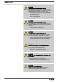
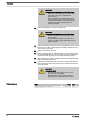
WARNING!
Warning about personal and material damage
The pump can start to pump, as soon as it is connected
to the mains voltage.
– Install an emergency cut-off switch in the pump
power supply line or integrate the pump in the emer‐
gency cut-off management of the system.
WARNING!
Danger of electric shock
A mains voltage may exist inside the pump housing.
– If the pump housing has been damaged, you must
disconnect it from the mains immediately. It may
only be returned to service after an authorised
repair.
WARNING!
Warning of hazardous feed chemical
Should a dangerous feed chemical be used: it may
escape from the hydraulic components when working on
the pump, material failure or incorrect handling of the
pump.
– Take appropriate protective measures before
working on the pump (e.g. safety glasses, safety
gloves, ...). Adhere to the material safety data sheet
for the feed chemical.
–
Drain and flush the liquid end before working on the
pump.
WARNING!
Fire danger
When pumping inflammable media the operator must
take suitable safety precautions.
WARNING!
Danger from hazardous substances!
Possible consequence: Fatal or very serious injuries.
Please ensure when handling hazardous substances
that you have read the latest safety data sheets provided
by the manufacture of the hazardous substance. The
actions required are described in the safety data sheet.
Check the safety data sheet regularly and replace, if
necessary, as the hazard potential of a substance can
be re-evaluated at any time based on new findings.
The system operator is responsible for ensuring that
these safety data sheets are available and that they are
kept up to date, as well as for producing an associated
hazard assessment for the workstations affected.
Safety information
Safety Chapter
9

CAUTION!
Warning of feed chemical spraying around
Feed chemical can spray out of the hydraulic compo‐
nents if they are manipulated or opened due to pressure
in the liquid end and adjacent parts of the system.
– Disconnect the pump from the mains power supply
and ensure that it cannot be switched on again by
unauthorised persons.
–
Depressurise the system before commencing any
work on hydraulic parts.
CAUTION!
Warning of feed chemical spraying around
The metering pump can generate a multiple of its rated
pressure. Hydraulic parts can rupture if a discharge line
is blocked.
– Correctly install a relief valve in the discharge line
downstream of the metering pump.
CAUTION!
Warning of feed chemical spraying around
An unsuitable feed chemical can damage the parts of
the pump that come into contact with the chemical.
– Take into account the resistance of the wetted mate‐
rials and the ProMinent Resistance List when
selecting the feed chemical - see the ProMinent
Product Catalogue or visit ProMinent.
CAUTION!
Danger of injury to personnel and material damage
The use of untested third party components can result in
injury to personnel and material damage.
– Only fit parts to metering pumps that have been
tested and recommended by ProMinent.
CAUTION!
Danger from incorrectly operated or inadequately main‐
tained pumps
Danger can arise from a poorly accessible pump due to
incorrect operation and poor maintenance.
– Ensure that the pump is accessible at all times.
– Adhere to the maintenance intervals.
CAUTION!
Danger from incorrect metering
Should a different liquid end size be fitted, this will
change the metering behaviour of the pump.
– Have the pump reprogrammed in the works.
Safety Chapter
10

CAUTION!
Warning against illegal operation
Observe the regulations that apply where the device is
installed.
n Dosing head
n Housing
n Hood (houses the control elements)
The dosing head may only be removed by the customer in accordance
with the "Repair" chapter.
The housing and the hood may only be removed by ProMinent customer
service department.
In an emergency, either pull out the mains plug, turn the multifunctional
switch to "Stop" or press the Emergency Stop switch installed on the cus‐
tomer's side or disconnect the pump from the mains power supply in line
with the emergency shut-down management guidelines for your system!
If feed chemical escapes, additionally ensure that the hydraulic system
around the pump is at atmospheric pressure. Adhere to the safety data
sheet for the feed chemical.
Task Qualification
Storage, transport, unpacking Instructed person
Assembly Technical personnel, service
Planning the hydraulic installation Qualified personnel who have a
thorough knowledge of metering
pumps
Hydraulic installation Technical personnel, service
Installation, electrical Electrical technician
Operation Instructed person
Maintenance, repair Technical personnel, service
Decommissioning, disposal Technical personnel, service
Troubleshooting Technical personnel, electrical
technician, instructed person,
service
Explanation of the table:
Qualified personnel
A qualified employee is deemed to be a person who is able to assess the
tasks assigned to him and recognise possible dangers based on his/her
technical training, knowledge and experience, as well as knowledge of
pertinent regulations.
Note:
A qualification of equal validity to a technical qualification can also be
gained by several years of employment in the relevant field of work.
Electrical technician
An electrical technician is able to complete work on electrical systems and
recognise and avoid possible dangers independently based on his/her
technical training and experience, as well as knowledge of pertinent stand‐
ards and regulations.
Fixed separating protective equipment
Information in the event of an emergency
Qualification of personnel
Safety Chapter
11

The electrical technician should be specifically trained for the working
environment in which he is employed and know the relevant standards
and regulations.
An electrical technician must comply with the provisions of the applicable
statutory directives on accident prevention.
Instructed person
An instructed person is deemed to be a person who has been instructed
and, if required, trained in the tasks assigned to him/her and possible dan‐
gers that could result from improper behaviour, as well as having been
instructed in the required protective equipment and protective measures.
Service
The Service department refers to service technicians, who have received
proven training and have been authorised by ProMinent to work on the
system.
Sound pressure level LpA < 70 dB according to EN ISO 20361
at maximum stroke length, maximum stroke rate, maximum back pressure
(water)
Sound pressure level
Safety Chapter
12

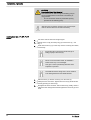
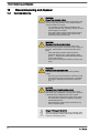
4 Storage, Transport and Unpacking
WARNING!
The transporting of pumps which have been used with
radioactive feed chemicals is forbidden!
They will also not be accepted by ProMinent!
WARNING!
Only return metering pumps for repair in a cleaned state
and with a flushed liquid end - refer to "Decommis‐
sioning!
Only return metering pumps with a completed Decon‐
tamination Declaration form. The Decontamination Dec‐
laration constitutes an integral part of an inspection /
repair order. A unit can only be inspected or repaired
when a Declaration of Decontamination Form is sub‐
mitted that has been completed correctly and in full by
an authorised and qualified person on behalf of the
pump operator.
The "Decontamination Declaration Form" can be found
on our homepage.
CAUTION!
Danger of material damage
The device can be damaged by incorrect or improper
storage or transportation!
– The unit should only be stored or transported in a
well packaged state - preferably in its original pack‐
aging.
–
The packaged unit should also only be stored or
transported in accordance with the stipulated
storage conditions.
– The packaged unit should be protected from mois‐
ture and the ingress of chemicals.
Data Value Unit
Minimum storage and transport tempera‐
ture
-20 °C
Maximum storage and transport tempera‐
ture
+60 °C
Maximum air humidity * 95 % rel.
humidity
* non-condensing
Compare the delivery note with the scope of delivery:
n Metering pump with mains cable
n Connector kit for hose/pipe connection (optional)
n Product-specific operating instructions with EC Declaration of Con‐
formity
n Optional accessories
Safety Information
Ambient conditions
Scope of delivery
Storage, Transport and Unpacking
13

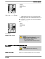
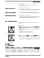
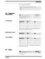
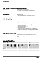
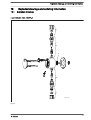
5 Overview of Equipment and Control Elements
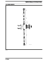
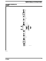
5.1
Overview of Equipment
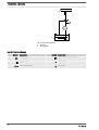
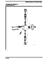
1 2 3
P_BE_0013_SW
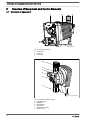
Fig. 2: Complete overview
1 Control unit
2 Drive unit
3 Liquid end
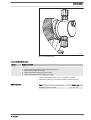
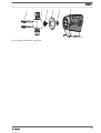
a
b
c
d
e
f
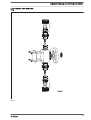
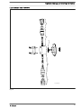
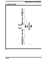
P_BE_0008_SW
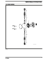
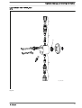
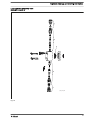
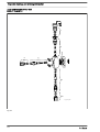
Fig. 3: Overview of liquid end (PV)
a Discharge valve
b Backplate
c Dosing head
d Bleed valve
e Bypass hose sleeve
f Suction valve
Overview of Equipment and Control Elements
14

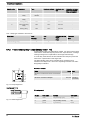
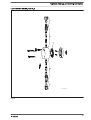
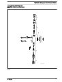
5.2 Control Elements
1
2
3
4
5
7
8
9
6
P_BE_0011_SW
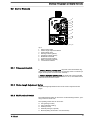
Fig. 4
1 Pulse control switch
2 Stroke Length Adjustment Button
3 Fault indicator (red)
4 Warning indicator (yellow)
5 Operating indicator (green)
6 Multifunctional Switch
7 "External control" terminal
8 Relay connection (optional)
9 "Level switch" terminal
5.2.1 Pulse control switch
In "External Contact" operating mode, the pulse control switch either trig‐
gers a series of strokes or steps down an incoming series of contacts by a
single contact (at the "external control" terminal).
In "External Analogue" operating mode, the stroke rate can be controlled
by an mA signal via the pulse control switch. To do so, the multifunctional
switch has to be turned to "Extern".
5.2.2 Stroke Length Adjustment Button
The stroke length adjustment button can be used to adjust the stroke
length.
5.2.3
Multifunctional Switch
The multifunctional switch can be used to set the following functions, oper‐
ating modes and stroke rate.
The operating modes that can be set are:
n Test (priming function)
n Stop (optionally missing)
n Extern (Contact)
n External (analogue, optional)
n Manual (setting stroke rate in 10% increments)
Overview of Equipment and Control Elements
15

5.2.4 Functional and Fault Indicators
The fault indicator lights up if the fluid level in the dosing tank falls below
the second switching point of the level switch (
20 mm residual filling level
in the dosing tank).
The fault indicator lights up if the current falls below 3.8 mA (only with
4...20 mA) or exceeds 23 mA in "External Analogue" operating mode.
This LED flashes in the event of an undefined operating status.
The warning indicator lights up if the fluid level in the dosing tank falls
below the first switching point of the level switch.
The operating indicator lights up if the pump is ready for operation and
there are no fault or warning alerts. It goes out quickly as soon as the
pump has performed a stroke.
5.2.5 "External control" terminal
The "external control" terminal is a five-pole panel terminal.
It enables the following functions and operating modes to be used:
n Pause
n External contact
n External Analogue (optional)
n Auxiliary frequency (external frequency changer)
The two- and four-pole cables used to date can continue
to be used. The "Auxiliary frequency" function can, how‐
ever, only be used with a five-pole cable.
5.2.6 "Level switch" terminal
A 2-stage level switch with pre-warning and end switch-off can be con‐
nected.
Fault indicator (red)
Warning indicator (yellow)
Operating indicator (green)
Overview of Equipment and Control Elements
16

6 Functional description
6.1
Liquid End
The dosing process is performed as follows: The diaphragm is pressed
into the dosing head; the pressure in the dosing head closes the suction
valve and the feed chemical flows through the discharge valve out of the
dosing head. The diaphragm is now drawn out of the dosing head; the dis‐
charge valve closes due to the negative pressure in the dosing head and
fresh feed chemical flows through the suction valve into the dosing head.
One cycle is completed.
6.2 Drive Unit
The diaphragm is driven by an electromagnet, which is controlled by an
electronic controller.
6.3 Capacity
The capacity is determined by the stroke length and the stroke rate.
The stroke length is adjusted by the stroke length adjustment knob within
a range of 0 ... 100 %. A stroke length of between 30 ... 100 % (SEK type:
50 ... 100 %) is recommended to achieve the specified reproducibility!
Data Value Unit
Recommended stroke length, standard
type
30 ... 100 %
Recommended stroke length, SEK type 50 ... 100 %
The stroke rate can be set within a range of 10 ... 100 % using the multi‐
functional switch.
6.4
Self-Bleeding
Self-bleeding liquid ends (SEK types) are capable of independent priming
when a discharge line is connected and diverting existent air pockets via a
bypass. During operation they are also capable of conveying away gases
which are produced, independently of the operating pressure in the
system. It is also possible to dose precisely in a depressurised state due
to the integral back pressure valve.
6.5
Operating modes
The operating modes are selected by means of the multifunctional switch.
As soon as the stroke rate has been set by the multifunctional switch, the
pump finds itself in "Manual" operating mode. 100% corresponds to 180
strokes/min.
The "External Contact" operating mode is described below in the "Opera‐
tion" and "Installation, Electrical" chapters.
The "External Analogue" operating mode is described below in the "Ope‐
ration" and "Installation, Electrical" chapters.
"Manual" operating mode
"External contact" operating mode
"External Analogue" operating mode
Functional description
17

6.6 Functions
The functions are described below in the "Operation" chapter.
6.7
Relay
The pump has two connecting options.
The relay can switch a connected power circuit (e.g. for an alarm horn) in
the event of warnings or fault messages (e.g. warning levels).
The relay can be retrofitted with the retrofit kit via a knock-out opening in
the pump foot - refer to "Retrofitting relays".
This combined relay can generate a contact with each stroke via its pacing
relay in addition to its function as a fault indicating relay.
The relay can be retrofitted with the retrofit kit via a knock-out opening in
the pump foot - refer to "Retrofitting relays".
6.8
Hierarchy of Operating Modes, Functions and Fault Statuses
The different operating modes, functions and fault statuses have a dif‐
ferent effect on if and how the pump reacts.
The following list shows the order:
1. - Test (priming)
2. - Fault, Stop, Pause
3. - Auxiliary frequency (external frequency changeover)
4. - Manual, Extern Contact
Comments:
re 1 - "Priming" can take place in any mode of the pump (providing it is
functioning).
re 2 - "Fault", "Stop" und "Pause" stop everything apart from "Priming".
re 3 - The stroke rate of "Auxiliary frequency" always has priority over the
stroke rate specified by an operating mode in 4.
Fault indicating relay option
Fault indicating and pacing relay option
Functional description
18

7 Assembly
–
Compare the dimensions on the dimension sheet
with those of the pump.
WARNING!
Danger of electric shock
If water or other electrically conducting liquids penetrate
into the drive housing, in any other manner than via the
pump's suction connection, an electric shock may occur.
– Position the pump so that it cannot be flooded.
CAUTION!
Danger from incorrectly operated or inadequately main‐
tained pumps
Danger can arise from a poorly accessible pump due to
incorrect operation and poor maintenance.
– Ensure that the pump is accessible at all times.
–
Adhere to the maintenance intervals.
Capacity too low
The liquid end valves can be disturbed by vibrations.
–
Secure the metering pump so that no vibrations can
occur.
Capacity too low
If the valves of the liquid end are not vertical, they
cannot close correctly.
–
Suction and discharge valves must stand vertically
upwards (for self-bleeding liquid end, the bleed
valve).
Mount the metering pump with the pump foot on a horizontal, level
and load-bearing supporting surface.
Assembly
19

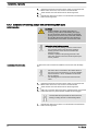
8 Installation, hydraulic
CAUTION!
Warning of feed chemical spraying around
An unsuitable feed chemical can damage the parts of
the pump that come into contact with the chemical.
– Take into account the resistance of the wetted mate‐
rials and the ProMinent Resistance List when
selecting the feed chemical - see the ProMinent
Product Catalogue or visit ProMinent.
CAUTION!
FDA pumps only: problems with hygiene possible
The O-rings supplied can become slightly contaminated
through packaging and shipment.
– Thoroughly clean the O-rings supplied before use.
CAUTION!
Warning of feed chemical spraying around
Pumps which are not fully installed hydraulically can
pump feed chemical from the outlet opening of the dis‐
charge valve as soon as they are connected to the
mains/power supply.
– First install the pump hydraulically, then electrically.
–
In the event that you have failed to do so, turn the
multifunctional switch to
[Stop]
(if fitted) or press an
On / Off switch or Emergency Stop switch on site.
CAUTION!
Warning of feed chemical spraying around
Feed chemical can spray out of the hydraulic compo‐
nents if they are manipulated or opened due to pressure
in the liquid end and adjacent parts of the system.
– Disconnect the pump from the mains power supply
and ensure that it cannot be switched on again by
unauthorised persons.
–
Depressurise the system before commencing any
work on hydraulic parts.
CAUTION!
Danger from rupturing hydraulic components
Peak loads during the dosing stroke can cause the max‐
imum permissible operating pressure of the system and
pump to be exceeded.
– The discharge lines are to be properly designed.
CAUTION!
Danger of personnel injury and material damage
The use of untested third party parts can result in per‐
sonnel injuries and material damage.
– Only fit parts to metering pumps, which have been
tested and recommended by ProMinent.
Safety information
Installation, hydraulic
20
Page is loading ...
Page is loading ...
Page is loading ...
Page is loading ...
Page is loading ...
Page is loading ...
Page is loading ...
Page is loading ...
Page is loading ...
Page is loading ...
Page is loading ...
Page is loading ...
Page is loading ...
Page is loading ...
Page is loading ...
Page is loading ...
Page is loading ...
Page is loading ...
Page is loading ...
Page is loading ...
Page is loading ...
Page is loading ...
Page is loading ...
Page is loading ...
Page is loading ...
Page is loading ...
Page is loading ...
Page is loading ...
Page is loading ...
Page is loading ...
Page is loading ...
Page is loading ...
Page is loading ...
Page is loading ...
Page is loading ...
Page is loading ...
Page is loading ...
Page is loading ...
Page is loading ...
Page is loading ...
Page is loading ...
Page is loading ...
Page is loading ...
Page is loading ...
Page is loading ...
Page is loading ...
Page is loading ...
Page is loading ...
Page is loading ...
Page is loading ...
Page is loading ...
Page is loading ...
Page is loading ...
Page is loading ...
Page is loading ...
Page is loading ...
Page is loading ...
Page is loading ...
Page is loading ...
Page is loading ...
Page is loading ...
Page is loading ...
Page is loading ...
Page is loading ...
Page is loading ...
Page is loading ...
Page is loading ...
Page is loading ...
Page is loading ...
Page is loading ...
Page is loading ...
Page is loading ...
Page is loading ...
Page is loading ...
Page is loading ...
Page is loading ...
Page is loading ...
Page is loading ...
Page is loading ...
Page is loading ...
Page is loading ...
Page is loading ...
Page is loading ...
Page is loading ...
Page is loading ...
Page is loading ...
Page is loading ...
Page is loading ...
Page is loading ...
Page is loading ...
Page is loading ...
Page is loading ...
Page is loading ...
Page is loading ...
Page is loading ...
Page is loading ...
Page is loading ...
Page is loading ...
Page is loading ...
Page is loading ...
Page is loading ...
Page is loading ...
Page is loading ...
Page is loading ...
-
 1
1
-
 2
2
-
 3
3
-
 4
4
-
 5
5
-
 6
6
-
 7
7
-
 8
8
-
 9
9
-
 10
10
-
 11
11
-
 12
12
-
 13
13
-
 14
14
-
 15
15
-
 16
16
-
 17
17
-
 18
18
-
 19
19
-
 20
20
-
 21
21
-
 22
22
-
 23
23
-
 24
24
-
 25
25
-
 26
26
-
 27
27
-
 28
28
-
 29
29
-
 30
30
-
 31
31
-
 32
32
-
 33
33
-
 34
34
-
 35
35
-
 36
36
-
 37
37
-
 38
38
-
 39
39
-
 40
40
-
 41
41
-
 42
42
-
 43
43
-
 44
44
-
 45
45
-
 46
46
-
 47
47
-
 48
48
-
 49
49
-
 50
50
-
 51
51
-
 52
52
-
 53
53
-
 54
54
-
 55
55
-
 56
56
-
 57
57
-
 58
58
-
 59
59
-
 60
60
-
 61
61
-
 62
62
-
 63
63
-
 64
64
-
 65
65
-
 66
66
-
 67
67
-
 68
68
-
 69
69
-
 70
70
-
 71
71
-
 72
72
-
 73
73
-
 74
74
-
 75
75
-
 76
76
-
 77
77
-
 78
78
-
 79
79
-
 80
80
-
 81
81
-
 82
82
-
 83
83
-
 84
84
-
 85
85
-
 86
86
-
 87
87
-
 88
88
-
 89
89
-
 90
90
-
 91
91
-
 92
92
-
 93
93
-
 94
94
-
 95
95
-
 96
96
-
 97
97
-
 98
98
-
 99
99
-
 100
100
-
 101
101
-
 102
102
-
 103
103
-
 104
104
-
 105
105
-
 106
106
-
 107
107
-
 108
108
-
 109
109
-
 110
110
-
 111
111
-
 112
112
-
 113
113
-
 114
114
-
 115
115
-
 116
116
-
 117
117
-
 118
118
-
 119
119
-
 120
120
-
 121
121
-
 122
122
-
 123
123
-
 124
124


ProMinent Beta b BT4b 1000 Operating Instructions Manual
- Type
- Operating Instructions Manual
Ask a question and I''ll find the answer in the document
Finding information in a document is now easier with AI
Related papers
-
ProMinent alpha ALPc 1002 Operating Instructions Manual
-
-
-
-
-
-
-
-
-
Other documents
-
Fairchild Lower Pressure Selector Relay User manual
-
 Whirlwind WLF482 User manual
-
Omega PHP-200 Series Owner's manual
-
Grundfos DME 375 Installation And Operating Instructions Manual
-
Grundfos DDE Installation And Operating Instructions Manual
-
-
-
Columbus HS 1601 User manual
-
-
Dover PSG NEPTUNE 637 Operation & Maintenance Manual
