
Solenoid Metering Pump
Beta
®
b BT4b and BT5b
Operating instructions
Original Operating Instructions (2006/42/EC)Part no. 986356 BA BE 026 04/12 EN
Please carefully read these operating instructions before use! · Do not discard!
The operator shall be liable for any damage caused by installation or operating errors!
Technical changes reserved.

986357, 3, en_GB
© 2009
ProMinent Dosiertechnik GmbH
Im Schuhmachergewann 5-11
D-69123 Heidelberg
Telephone: +49 6221 842-0
Fax: +49 6221 842-617
email: [email protected]
Internet: www.prominent.com
2

Read the following supplementary information in its entirety! Should you
already know this information, you have an even greater need of the Oper‐
ating Instructions.
The following are highlighted separately in the document:
n Enumerated lists
Instructions
ð
Outcome of the instructions
Information
This provides important information relating to the correct
operation of the device or is intended to make your work
easier.
Safety notes
Safety notes are identified by pictograms - see Safety Chapter.
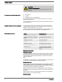
Two sets of operating instructions are required for the safe, correct and
proper operation of the metering pumps: The product-specific operating
instructions and the "General Operating Instructions for ProMinent
®
Sole‐
noid Metering Pumps".
Both sets of operating instructions are only valid when read together.
Please read these operating instructions carefully before use! Do not dis‐
card!
Please state identity code and serial number, which you can find on the
nameplate when you contact us or order spare parts. This enables the
device type and material versions to be clearly identified.
In order to make it easier to read, this document uses the male form in
grammatical structures but with an implied neutral sense. It is aimed
equally at both men and women. We kindly ask female readers for their
understanding in this simplification of the text.
Supplementary information
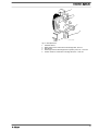
Fig. 1: Please read!
General user instructions
State the identity code and serial number
General non-discriminatory approach
Supplemental instructions
3

Table of contents
1 Identity code ................................................................................... 6
2
About this pump............................................................................... 8
3 Safety chapter................................................................................. 9
4 Storage, transport and unpacking................................................. 14
5 Overview of equipment and control elements............................... 16
5.1 Overview of equipment......................................................... 16
5.2 Control elements................................................................... 17
5.2.1 Pulse Control Switch.......................................................... 17
5.2.2 Stroke length adjustment knob........................................... 17
5.2.3 Multifunctional switch......................................................... 17
5.2.4 Functional and Fault Indicators.......................................... 18
5.2.5 "External control" terminal.................................................. 18
5.2.6 "Level Switch" terminal....................................................... 18
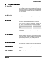
6 Functional description.................................................................... 19
6.1 Liquid End............................................................................. 19
6.2 Drive Unit.............................................................................. 19
6.3 Capacity................................................................................ 19
6.4 Self-Bleeding......................................................................... 19
6.5 Operating Modes .................................................................. 19
6.6 Functions............................................................................... 20
6.7 Relay..................................................................................... 20
6.8 Hierarchy of Operating Modes, Functions and Fault Sta‐
tuses...................................................................................... 20
7 Assembly
....................................................................................... 21
8 Installation, hydraulic..................................................................... 22
8.1 Install hose lines.................................................................... 23
8.1.1 Installation for metering pumps without bleed valve.......... 23
8.1.2 Installation for metering pumps with bleed valve............... 25
8.1.3 Installation for metering pumps with self-bleeding (SEK
type)................................................................................... 26
9 Electrical installation...................................................................... 28
9.1 Supply voltage connector...................................................... 29
9.2 Description of the sockets..................................................... 29
9.2.1 "External control" terminal.................................................. 29
9.2.2 "Level Switch" terminal....................................................... 31
9.3 Relay..................................................................................... 31
9.3.1 "Fault indicating relay" output (identity code 1 + 3 or 4 +
5)........................................................................................ 31
9.3.2 Output pacing relay (identity code 4 + 5)........................... 32
10 Operation....................................................................................... 33
10.1 Manual................................................................................ 33
10.1.1 Capacity........................................................................... 33
10.1.2 Functions.......................................................................... 33
10.1.3 External contact............................................................... 34
10.2 Remote operation................................................................ 34
11 Maintenance.................................................................................. 35
12 Repairs.......................................................................................... 37
12.1 Cleaning valves................................................................... 37
12.2
Replacing the metering diaphragm..................................... 39
13 Troubleshooting............................................................................. 42
13.1 Faults without a fault alert................................................... 42
13.2 Fault alerts.......................................................................... 42
Table of contents
4

13.3 Warning Alerts..................................................................... 43
13.4 All Other Faults................................................................... 43
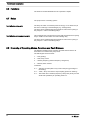
14 Decommissioning.......................................................................... 44
15
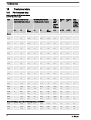
Technical data............................................................................... 46
15.1
Performance data
................................................................ 46
15.2 Accuracy............................................................................. 47
15.2.1 Standard Liquid End......................................................... 47
15.2.2 Self-Bleeding Liquid End.................................................. 48
15.3 Viscosity.............................................................................. 48
15.4 Material Data....................................................................... 48
15.5 Electrical data...................................................................... 49
15.6 Temperatures...................................................................... 49
15.7 Climate................................................................................ 50
15.8 Protection class and Safety Requirements......................... 50
15.9 Compatibility........................................................................ 50
15.10 Sound pressure level........................................................ 51
15.11 Shipping weight................................................................. 51
16 Declaration of Conformity.............................................................. 52
17 Index.............................................................................................. 53
Table of contents
5

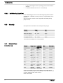
1
Identity code
Product range Beta b
BT4
b
Type Performance
bar l/h
1000 10 0.74
1601 16 1.10
1602 16 2.20
1604 16 3.60
0708 7 7.10
0413 4 12.30
0220 2 19.00
BT5
b
2504 25 2.90
1008 10 6.80
0713 7 11.00
0420 4 17.10
0232 2 32.00
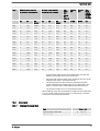
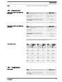
Material of dosing head/valves
PP Polypropylene/PVDF. With the self-bleeding version (SEK): polypropylene/polypropylene
NP Clear acrylic/PVDF. With the self-bleeding version (SEK): Clear acrylic/PVC
PV PVDF/PVDF
TT PTFE/PTFE
SS Stainless steel 1.4404/1.4404
Material of seals/diaphragm
T PTFE/PTFE coated
E EPDM/PTFE coated, only for PP and NP self-bleeding (SEK)
B FPM-B/PTFE coated, only for PP and NP self-bleeding (SEK)
S Diaphragm additionally with FPM coating for media containing silicate
Dosing head version
0 without bleed valve, without valve spring only for NP, TT, SS and type 0232
1 without bleed valve, with valve spring only for NP, TT, SS and type 0232
2 with bleed valve, without valve spring only for PP, PV, NP not for type 0232
3 with bleed valve, with valve spring only for PP, PV, NP not for type 0232
4 version for higher-viscous media only for PVT, type 1604, 2504, 0708, 1008, 0413,
0713, 0220, 0420
9 self-bleeding (SEK) only for PP/NP, not for types 1000 and 0232
Hydraulic connector
0 Standard connection in line with technical data
5 Connector for 12/6 tube, discharge side only
9 Connector for 10/4 tube, discharge side only
Identity code
6

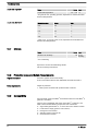
Product range Beta b
Design
0 Standard
Logo
0 with ProMinent logo
Electrical connection
U 100-230 V ± 10 %, 50/60 Hz
Cable and plug
A 2 m European
B 2 m Swiss
C 2 m Australian
D 2 m USA
1 2 m open end
Relay
0 No relay
1 fault indicating relay (NC) (change-over relay)
3 fault indicating relay (NO) (change-over relay)
4 as 1 + pacing relay, (ONE each)
5 as 3 + pacing relay, (ONE each)
Accessories
0 No accessories
1 with foot and injection valve, 2 m PVC suction
line, 5 m metering line
Control type
0 no lock
1 with lock: manual operation locked when
external cable plugged in
Control versions
0 Standard
Options
00 no options
Identity code
7

2
About this pump
This solenoid metering pump Beta b is equipped with all adjustment and
activation functions for modern water treatment and the dosing of chemi‐
cals. It has pulse step-up and pulse step-down compared with the pre‐
ceding model. This enables it to adapt more precisely to external signal
generators. The result is the simpler and more precise adjustment of
chemical consumption to the actual need. It also has a 10 percent
increase in efficiency and energy efficiency over the preceding model. The
Beta b can be simply adjusted during operation.
Properties of the device
About this pump
8

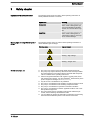
3
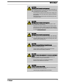
Safety chapter
The following signal words are used in these operating instructions to
identify different severities of a hazard:
Signal word Meaning
WARNING Denotes a possibly hazardous sit‐
uation. If this is disregarded, you
are in a life-threatening situation
and this can result in serious inju‐
ries.
CAUTION Denotes a possibly hazardous sit‐
uation. If this is disregarded, it
could result in slight or minor inju‐
ries or material damage.
The following warning signs are used in these operating instructions to
denote different types of danger:
Warning signs Type of danger
Warning – automatic start-up.
Warning – high-voltage.
Warning – danger zone.
n The pump may only be used to meter liquid metering chemicals.
n The pump may only be started up after it has been correctly installed
and commissioned in accordance with the technical data and specifi‐
cations contained in the operating instructions.
n Observe the general limitations with regard to viscosity limits, chem‐
ical resistance and density - see also ProMinent
®
resistance list (In the
product equipment catalogue or at
www.prominent.com
).
n Any other uses or modifications are prohibited.
n The pump is not intended for the metering of gaseous media or solids.
n The pump is not intended for the metering of explosive media.
n The pump is not intended for operation in hazardous locations.
n The pump is not intended for exterior applications without use of suit‐
able protective equipment.
n The pump should only be operated by trained and authorised per‐
sonnel, see the following "Qualifications" table.
n You are obliged to observe the information contained in the operating
instructions at the different phases of the device's service life.
Explanation of the safety information
Warning signs denoting different types of
danger
Correct and proper use
Safety chapter
9

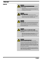
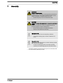
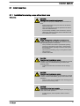
WARNING!
Warning about personal and material damage
The pump can start to pump, as soon as it is connected to
the mains voltage.
– Install an emergency cut-off switch in the pump power
supply line or integrate the pump in the emergency cut-
off management of the system.
WARNING!
Danger of electric shock
A mains voltage may exist inside the pump housing.
– If the pump housing has been damaged, you must dis‐
connect it from the mains immediately. It may only be
returned to service after an authorised repair.
WARNING!
Fire danger
Combustible media may only be transported using stainless
steel dosing heads. In exceptional cases where this is not
possible, PTFE with carbon can be used, whereby our TT_
versions are manufactured from this conducting plastic.
Here, the operator is urged to take special care due to the
low mechanical strength.
WARNING!
Warning of dangerous or unknown feed chemical
Should a dangerous or unknown feed chemical be used: It
may escape from the hydraulic components when working
on the pump.
– Take appropriate protective measures before working on
the pump (e.g. safety glasses, safety gloves, ...).
Observe the safety data sheet for the feed chemical.
– Drain and flush the liquid end before working on the
pump.
WARNING!
Danger from hazardous substances!
Possible consequence: Fatal or very serious injuries.
Please ensure when handling hazardous substances that
you have read the latest safety data sheets provided by the
manufacture of the hazardous substance. The actions
required are described in the safety data sheet. Check the
safety data sheet regularly and replace, if necessary, as the
hazard potential of a substance can be re-evaluated at any
time based on new findings.
The system operator is responsible for ensuring that these
safety data sheets are available and that they are kept up to
date, as well as for producing an associated hazard assess‐
ment for the workstations affected.
Safety notes
Safety chapter
10

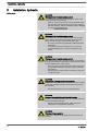
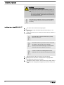
CAUTION!
Warning of feed chemical spraying around
Feed chemical can spray out of the hydraulic components if
they are manipulated or opened due to pressure in the liquid
end and adjacent parts of the system.
– Disconnect the pump from the mains power supply and
ensure that it cannot be switched on again by unauthor‐
ised persons.
– Depressurise the system before commencing any work
on hydraulic parts.
CAUTION!
Warning of feed chemical spraying around
An unsuitable feed chemical can damage the parts of the
pump contacted by the chemical.
– Take into account the resistance of the materials which
will come into contact with the chemical when selecting
the feed chemical - see the ProMinent product catalogue
or under
www.prominent.com
.
CAUTION!
Warning of feed chemical spraying around
The metering pump can generate a multiple of its rated pres‐
sure. If a discharge line is blocked, hydraulic parts may burst.
– Correctly install a relief valve in the discharge line down‐
stream of the metering pump.
CAUTION!
Danger of personnel injury and material damage
The use of untested third party parts can result in personnel
injuries and material damage.
– Only fit parts to metering pumps, which have been
tested and recommended by ProMinent.
CAUTION!
Danger from incorrectly operated or inadequately maintained
pumps
Danger can arise from a poorly accessible pump due to
incorrect operation and poor maintenance.
– Ensure that the pump is accessible at all times.
– Adhere to the maintenance intervals.
CAUTION!
Danger from incorrect metering
Should a different liquid end size be fitted, this will change
the metering behaviour of the pump.
– Have the pump reprogrammed in the works.
Safety chapter
11

CAUTION!
Warning of illegal operation
Observe the regulations that apply where the unit is to be
installed.
n Dosing head
n Housing
n Hood (houses the control elements)
The dosing head may only be removed by the customer in accordance
with the "Repair" chapter.
The housing and the hood may only be removed by ProMinent customer
service department.
In an emergency, either pull out the mains plug or press the customer
installed emergency-off switch or disconnect the pump according to the
emergency-off management for your system!
If feed chemical escapes, also depressurise the hydraulic system around
the pump. Adhere to the safety data sheet for the feed chemical.
Activity Qualification level
Storage, transport, unpacking Instructed person
Assembly, installation of hydraulic
system
Technical personnel, service
Installation, electrical Electrical technician
Operation Instructed person
Maintenance, repair Technical personnel, service
Decommissioning, disposal Technical personnel, service
Troubleshooting Technical personnel, electrical
technician, instructed person,
service
Explanation of the terms:
Technical personnel
A qualified employee is deemed to be a person who is able to assess the
tasks assigned to him and recognise possible dangers based on his/her
technical training, knowledge and experience, as well as knowledge of
pertinent regulations.
Note:
A qualification of equal validity to a technical qualification can also gained
by several years employment in the relevant work area.
Electrical technician
Electrical technicians are deemed to be people, who are able to complete
work on electrical systems and recognize and avoid possible dangers
independently based on their technical training and experience, as well as
knowledge of pertinent standards and regulations.
Electrical technicians should be specifically trained for the working envi‐
ronment in which the are employed and know the relevant standards and
regulations.
Electrical technicians must comply with the provisions of the applicable
statutory directives on accident prevention.
Instructed person
Fixed separating protective equipment
Information in the event of an emergency
Qualification of personnel
Safety chapter
12

An instructed person is deemed to be a person who has been instructed
and, if required, trained in the tasks assigned to him/her and possible dan‐
gers that could result from improper behaviour, as well as having been
instructed in the required protective equipment and protective measures.
Service
Customer Service department refers to service technicians, who have
received proven training and have been authorised by ProMinent or Pro‐
Maqua to work on the system.
Sound pressure level LpA < 70 dB in accordance with EN ISO
20361:2010-10
at maximum stroke length, maximum stroke rate, maximum back pressure
(water)
Sound pressure level
Safety chapter
13

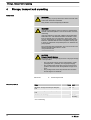
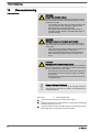
4
Storage, transport and unpacking
WARNING!
The transporting of pumps which have been used with radio‐
active feed chemicals is forbidden!
They will also not be accepted by ProMinent!
WARNING!
Only return the metering pump for repair in a cleaned state
and with a flushed liquid end - refer to the section on decom‐
missioning!
Only send metering pumps with a filled in Decontamination
Declaration form. The Decontamination Declaration consti‐
tutes an integral part of an inspection / repair order. A unit
can only be inspected or repaired if a Decontamination Dec‐
laration is submitted that has been completed correctly and
in full by an authorised and qualified person on behalf of the
pump operator.
The "Decontamination Declaration" form can be found in the
General Operating Instructions or under
www.prominent.com
.
CAUTION!
Danger of material damage
The device can be damaged by incorrect or improper storage
or transportation!
– The unit should only be stored or transported in a well
packaged state - preferably in its original packaging.
– The packaged unit should also only be stored or trans‐
ported in accordance with the stipulated storage condi‐
tions.
– The packaged unit should be protected from moisture
and the ingress of chemicals.
Personnel:
n
Technical personnel
Data Value Unit
Minimum storage and transport tempera‐
ture
-20 °C
Maximum storage and transport tempera‐
ture
+60 °C
Maximum air humidity * 95 % rel.
humidity
* non-condensing
Safety notes
Ambient conditions
Storage, transport and unpacking
14

Compare the delivery note with the scope of supply:
n Metering pump with mains power cable
n Connector kit for tube/pipe connection
n Product-specific operating instructions with EC Declaration of Con‐
formity
n CD with order information, exploded diagrams, performance diagrams
and data sheets
n Optional accessories if ordered
Scope of supply
Storage, transport and unpacking
15

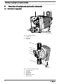
5
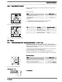
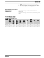
Overview of equipment and control elements
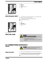
5.1
Overview of equipment
1 2 3
P_BE_0013_SW
Fig. 2: Complete overview
1 Control unit
2 Drive unit
3 Liquid end
a
b
c
d
e
f
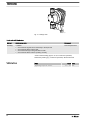
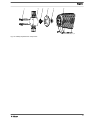
P_BE_0008_SW
Fig. 3: Overview of liquid end (PV)
a Discharge valve
b Backplate
g Dosing head
d Bleed valve
e Bypass hose nozzle
f Suction valve
Overview of equipment and control elements
16

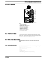
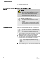
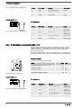
5.2
Control elements
1
2
3
4
5
7
8
9
6
P_BE_001
1_SW
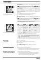
Fig. 4
1 Pulse Control Switch
2 Stroke length adjustment knob
3 Fault indicator (red)
4 Warning indicator (yellow)
5 Operating indicator (green)
6 Multifunctional switch
7 "External control" terminal
8 Relay connection (optional)
9 "Level Switch" terminal
5.2.1
Pulse Control Switch
In Extern Contact operating mode via the pulse control switch a single
contact (at the "external control" terminal) can be used to trigger a series
of strokes or to support an incoming series of contacts.
5.2.2
Stroke length adjustment knob
The stroke length adjustment knob can be used to adjust the stroke
length.
5.2.3
Multifunctional switch
The multifunctional switch can be used to set the following functions, oper‐
ating modes and stroke rate.
The operating modes that can be set are:
n Test (priming function)
n Stop
n Extern (Contact)
n Manual (setting stroke rate in 10 % increments)
Overview of equipment and control elements
17

5.2.4
Functional and Fault Indicators
The fault indicator lights up if the liquid level in the chemical feed container
falls below the second switching point of the level switch (
20 mm residual
filling level in the chemical feed container).
This LED flashes in the event of an undefined operating mode.
The warning indicator lights up if the fluid level in the chemical feed con‐
tainer falls below the first switching point of the level switch.
The operating indicator lights up if the pump is ready for operation and
there are no fault or warning alerts. It goes out quickly as soon as the
pump has performed a stroke.
5.2.5
"External control" terminal
The "external control" terminal is a five-pole panel terminal.
It enables the following functions and operating modes to be used:
n Pause
n External contact
n Auxiliary frequency (external frequency changeover)
The two- and four-pole cables used to date can continue to
be used. The "Auxiliary frequency" function can, however,
only be used with a five-pole cable.
5.2.6
"Level Switch" terminal
A 2-stage level switch with pre-warning and end switch-off can be con‐
nected.
Fault indicator (red)
Warning indicator (yellow)
Operating indicator (green)
Overview of equipment and control elements
18

6
Functional description
6.1
Liquid End
The dosing process is performed as follows: The diaphragm is pressed
into the dosing head; the pressure in the dosing head closes the suction
valve and the feed chemical flows through the discharge valve out of the
dosing head. The diaphragm is now drawn out of the dosing head; the dis‐
charge valve closes due to the negative pressure in the dosing head and
fresh feed chemical flows through the suction valve into the dosing head.
One cycle is completed.
6.2
Drive Unit
The diaphragm is driven by an electromagnet, which is controlled by an
electronic controller.
6.3
Capacity
The capacity is determined by the stroke length and the stroke rate.
The stroke length is adjusted by the stroke length adjustment knob within
a range of 0 ... 100 %. A stroke length of between 30 ... 100 % (SEK type:
50 ... 100 %) is recommended to achieve the specified reproducibility!
Data Value Unit
Recommended stroke length, standard
type
30 ... 100 %
Recommended stroke length, SEK type 50 ... 100 %
The stroke rate can be set within a range of 10 ... 100 % using the multi‐
functional switch.
6.4
Self-Bleeding
Self-bleeding liquid ends (SEK types) are capable of independent priming
when a discharge line is connected and diverting existent air pockets via a
bypass. During operation they are also capable of conveying away gases
which are produced, independently of the operating pressure in the
system. It is also possible to dose precisely in a depressurised state due
to the integral back pressure valve.
6.5
Operating Modes
The operating modes are selected by means of the multifunctional switch.
As soon as the stroke rate has been set by the multifunctional switch, the
pump finds itself in "Manual" operating mode. 100 % corresponds to 180
strokes/min.
The "Extern" operating mode is described below in the "Operation"
chapter.
"Manual" operating mode
"Extern" operating mode:
Functional description
19

6.6
Functions
The functions are described below in the "Operation" chapter.
6.7
Relay
The pump has two connecting options.
The relay can switch a connected power circuit (e.g. for an alarm horn) in
the event of warnings or fault messages (e.g. warning levels).
The relay can be retrofitted with the retrofit kit via a knock-out opening in
the pump foot - refer to "Retrofitting relays".
This combined relay can generate a contact with each stroke via its pacing
relay in addition to its function as a fault indicating relay.
The relay can be retrofitted with the retrofit kit via a knock-out opening in
the pump foot - refer to "Retrofitting relays".
6.8
Hierarchy of Operating Modes, Functions and Fault Statuses
The different operating modes, functions and fault statuses have a dif‐
ferent effect on if and how the pump reacts.
The following list shows the order:
1. - Test (priming)
2. - Fault, Stop, Pause
3. - Auxiliary frequency (external frequency changeover)
4. - Manual, Extern Contact
Comments:
re 1 - "Priming" can take place in any mode of the pump (providing it is
functioning).
re 2 - "Fault", "Stop" und "Pause" stop everything apart from "Priming".
re 3 - The stroke rate of "Auxiliary frequency" always has priority over the
stroke rate specified by an operating mode in 4.
Fault indicating relay option
Fault indicating and pacing relay option
Functional description
20
Page is loading ...
Page is loading ...
Page is loading ...
Page is loading ...
Page is loading ...
Page is loading ...
Page is loading ...
Page is loading ...
Page is loading ...
Page is loading ...
Page is loading ...
Page is loading ...
Page is loading ...
Page is loading ...
Page is loading ...
Page is loading ...
Page is loading ...
Page is loading ...
Page is loading ...
Page is loading ...
Page is loading ...
Page is loading ...
Page is loading ...
Page is loading ...
Page is loading ...
Page is loading ...
Page is loading ...
Page is loading ...
Page is loading ...
Page is loading ...
Page is loading ...
Page is loading ...
Page is loading ...
Page is loading ...
-
 1
1
-
 2
2
-
 3
3
-
 4
4
-
 5
5
-
 6
6
-
 7
7
-
 8
8
-
 9
9
-
 10
10
-
 11
11
-
 12
12
-
 13
13
-
 14
14
-
 15
15
-
 16
16
-
 17
17
-
 18
18
-
 19
19
-
 20
20
-
 21
21
-
 22
22
-
 23
23
-
 24
24
-
 25
25
-
 26
26
-
 27
27
-
 28
28
-
 29
29
-
 30
30
-
 31
31
-
 32
32
-
 33
33
-
 34
34
-
 35
35
-
 36
36
-
 37
37
-
 38
38
-
 39
39
-
 40
40
-
 41
41
-
 42
42
-
 43
43
-
 44
44
-
 45
45
-
 46
46
-
 47
47
-
 48
48
-
 49
49
-
 50
50
-
 51
51
-
 52
52
-
 53
53
-
 54
54


ProMinent Beta BT5b Operating Instructions Manual
- Type
- Operating Instructions Manual
- This manual is also suitable for
Ask a question and I''ll find the answer in the document
Finding information in a document is now easier with AI
Related papers
-
ProMinent alpha ALPc 1002 Operating Instructions Manual
-
-
-
-
-
-
-
-
-
Other documents
-
 T & S Brass & Bronze Works B-0974 Datasheet
-
Fairchild Lower Pressure Selector Relay User manual
-
Pulsafeeder X030-XC-BAA8XXX Owner's manual
-
Pulsafeeder X068-XA-AAASXXX Owner's manual
-
Omega PHP-200 Series Owner's manual
-
-
Grundfos DME 375 Installation And Operating Instructions Manual
-
-
Columbus HS 1601 User manual
-
 AND AX-ST-CH-M4 User manual

