Page is loading ...

Metering pump
ProMinent EXtronic
®
EXBb
Operating instructions
0158
EN
Original operating instructions (2006/42/EC)Part No. 987094 BA EX 0 16 09/19 EN
Please carefully read these operating instructions before use. · Do not discard.
The operator shall be liable for any damage caused by installation or operating errors.
The latest version of the operating instructions are available on our homepage.

Read the following supplementary information in its entirety! You
will benefit more from using the operating instructions should you
already know this information.
The following are highlighted separately in the document:
n Enumerated lists
Instructions
ð
Outcome of the instructions
Ä ‘State the identity code and serial number’ on page 2
: Links to
points in this chapter
- refer to ... : References to points in this document or another
document
[Keys]
Information
This provides important information relating to the
correct operation of the unit or is intended to make
your work easier.
Safety Information
Safety information is identified by pictograms - see Safety Chapter.
These operating instructions conform to current EU regulations
applicable at the time of publication.
Please state identity code and serial number, which you can find
on the nameplate when you contact us or order spare parts. This
enables us to clearly identify the unit type and material versions.
Supplementary information
Fig. 1: Please read!
Validity
State the identity code and serial
number
Supplemental directives
2

Table of contents
1
Identity code.......................................................................... 5
2 Safety chapter....................................................................... 7
3 Storage, transport and unpacking....................................... 12
4 Overview of equipment....................................................... 13
5 Functional description......................................................... 15
5.1 Drive Unit.................................................................... 15
5.2 Liquid End................................................................... 15
5.3 Self-Bleeding.............................................................. 15
5.4 Diaphragm rupture sensor (optional).......................... 15
5.5 Metering rate............................................................... 16
5.6 Control types............................................................... 17
5.7 Button for maximum stroke rate.................................. 17
6 Assembly............................................................................ 18
7
Installation, hydraulic.......................................................... 19
7.1 Standard installation................................................... 22
7.2 Information on the suction-side installation................. 22
7.3 Information on the discharge-side installation............ 23
7.4 How not to install........................................................ 24
7.5 Special installation instructions................................... 25
8 Installation, electrical........................................................... 27
9 Start up............................................................................... 31
9.1 Determining pump capacity........................................ 33
9.2 Setting the pump capacity.......................................... 34
10 Troubleshooting.................................................................. 36
11 Maintenance....................................................................... 38
12 Repair................................................................................. 40
12.1 Replacing metering diaphragm................................. 40
12.2 Checking diaphragm rupture sensor......................... 42
12.3 Replacing separating diaphragm of the diaphragm
rupture sensor........................................................... 43
12.4 Installing dosing head............................................... 43
13 Decommissioning and disposal.......................................... 45
13.1 Decommissioning..................................................... 45
13.2 Disposal.................................................................... 46
14 Technical data..................................................................... 47
14.1 Performance data..................................................... 47
14.2 Precision................................................................... 49
14.3 Material specifications.............................................. 50
14.4 Weight....................................................................... 50
14.5 Electrical data........................................................... 50
14.5.1 Electrical data for actuation current circuits........... 50
14.5.2 Electrical data for supply current circuit................. 52
14.5.3 Electrical data, details............................................ 52
14.6 Ambient conditions................................................... 54
14.7 Sound pressure level................................................ 54
15 Dimensional drawing........................................................... 55
16 Nomographs....................................................................... 58
Table of contents
3


1 Identity code
Product range ProMinent EXtronic
®
, Version b
EXBb Degree of protection
G Gas explosion protection
M Firedamp and gas explosion protection
Pump
type
bar l/h
refer to nameplate
Dosing head material
PP1 PP with bleed valve, O-ring: EPDM
PP4 PP without bleed valve/ HV, O-ring: EPDM
NP1 Acrylic with bleed valve, O-ring: FPM-A
NP3 Acrylic with bleed valve, O-ring: FPM-A
NS3 Acrylic self-bleeding, O-ring: FPM-A
PS3 PVC self-bleeding, O-ring: FPM-A
TT1 PTFE + 25% carbon, flat seal: PTFE
SS1 Stainless steel 1.4571 with clamp rings, flat seal: PTFE
SS2 Stainless steel 1.4571 with internal thread1/4” NPT, seal: PTFE
SB1 Stainless steel 1.4571 with internal thread, Rp 1/4 or 1/2
SSM As SS1, with diaphragm rupture sensor
SBM As SB1, with diaphragm rupture sensor
Valve spring
0 With valve spring
1 With 2 valve springs (1.4571), 0.1 bar
Electrical connection
A 230 V, 50/60 Hz, open end
B 115 V, 50/60 Hz, open end
C 200 V, 50/60 Hz, open end
D 100 V, 50/60 Hz, open end
E 500 V, 50/60 Hz, open end
Control type
0 Internal stroke rate setting
1 External contact control
2 Analogue control 0–20 mA
3 Analogue control 4–20 mA
4 External contact control [i,a]
5 Analogue control 0–20 mA [i,a]
6 Analogue control 4–20 mA [i,a]
7 Manual with potential-free ON / OFF
Identity code
5

Product range ProMinent EXtronic
®
, Version b
8 Manual with potential-free ON / OFF, [i,a]
Control version
0 with potentiometer
1 with push-button for maximum frequency
2 with push-button switch-over for maximum
frequency
Certification/voltage/language
0 BVS Europe / 100–500 V / German
1 BVS Europe / 100–500 V / English
2 FM-USA / 115 V / English
3 CSA Canada / 115 V, 230 V / English
Identity code
6

2 Safety chapter
The following signal words are used in these operating instructions
to denote different severities of danger:
Signal word Meaning
WARNING Denotes a possibly dangerous
situation. If this is disregarded,
you are in a life-threatening sit‐
uation and this can result in
serious injuries.
CAUTION Denotes a possibly dangerous
situation. If this is disregarded,
it could result in slight or minor
injuries or material damage.
The following warning signs are used in these operating instruc‐
tions to denote different types of danger:
Warning signs Type of danger
Warning – high-voltage.
Warning – danger zone.
n Only use the pump to meter liquid feed chemicals.
n In potentially explosive premises, the pump may only be oper‐
ated with the appropriate nameplate (and the respective Decla‐
ration of Conformity) for pumps for use in areas at risk of explo‐
sion in compliance with Directive 2014/34/EU in accordance
with the European guidelines. The explosion group, category
and degree of protection specified on the label must corre‐
spond to or be better than the conditions in the intended appli‐
cation.
n The pump may only be used after it has been correctly
installed and started up in accordance with the technical data
and specifications contained in the operating instructions.
n Observe the general limitations with regard to viscosity limits,
chemical resistance and density - see also ProMinent
®
Resist‐
ance List in the Product Catalogue or at
www.prominent.com
!
n All other uses or modifications are prohibited.
n Never operate pumps in premises at risk of explosion without
the relevant nameplate (and the respective EU Declaration of
Conformity) for pumps for premises at risk of explosion.
n The pump is not intended for the metering of gaseous media
and solids.
n The pump is not intended for the metering of flammable media
without implementing suitable protective measures. Only the
“SB” design is approved for this.
n The pump is not designed to meter explosive media or mix‐
tures.
Identification of safety notes
Warning signs denoting different
types of danger
Intended use
Safety chapter
7

n The pump is not intended for exterior applications without the
implementation of suitable protective measures.
n The pump should only be operated by trained and authorised
personnel - see the following "Qualifications" table.
n You have a responsibility to adhere to the information con‐
tained in the operating instructions at the different phases of
the unit's service life.
Task Qualification
Storage, transport, unpacking Instructed person
Assembly Technical personnel, service
Planning the hydraulic installa‐
tion
Technical personnel who have
a thorough knowledge of dia‐
phragm pumps
Hydraulic installation Technical personnel, service
Electrical installation Electrical technician with knowl‐
edge of explosion protection
Operation Instructed person
Maintenance, repair Technical personnel, service
Decommissioning, disposal Technical personnel, service
Troubleshooting Technical personnel, electrical
technician with knowledge of
explosion protection, instructed
person, service
Explanation of the table:
Technical personnel
Technical personnel are deemed to be people who are able to
assess the tasks assigned to them and recognise possible dangers
based on their technical training, knowledge and experience, as
well as knowledge of pertinent regulations.
Note:
A qualification of equal validity to a technical qualification can also
be gained by several years of employment in the relevant field of
work.
Electrical technician with knowledge of explosion protection
An electrical technician with an additional explosion protection
qualification should be specifically trained for the field of work in
which he is employed and be familiar with the relevant standards
and regulations.
An electrical technician with an additional explosion protection
qualification can work on electrical systems and independently rec‐
ognise and avoid possible dangers based on his technical training
and experience.
The electrical technician with an additional explosion protection
qualification is familiar with all the standards and regulations appli‐
cable to explosion protection, in particular, but not however exclu‐
sively, with all parts of EN 60079 [Electrical equipment for areas at
risk of a gas explosion].
An electrical technician with an additional explosion protection
qualification must comply with the provisions of the applicable stat‐
utory directives on accident prevention.
Qualification of personnel
Safety chapter
8

Instructed person
An instructed person is deemed to be a person who has been
instructed and, if required, trained in the tasks assigned to him/her
and possible dangers that could result from improper behaviour, as
well as having been instructed in the required protective equipment
and protective measures.
Service
The Service department refers to service technicians, who have
received proven training and have been authorised by ProMinent
to work on the system.
WARNING!
Warning of personal injury and material damage
– The pump may start to pump as soon as it is
connected to mains voltage.
–
Mains voltage may be present inside the pump
housing.
– Should a dangerous or unknown feed chemical
be used: It may escape from the hydraulic
components when working on the pump.
– When pumping flammable media the operator
must take suitable safety precautions.
WARNING!
Danger from hazardous substances!
Possible consequence: Fatal or very serious inju‐
ries.
Please ensure when handling hazardous sub‐
stances that you have read the latest safety data
sheets provided by the manufacture of the haz‐
ardous substance. The actions required are
described in the safety data sheet. Check the
safety data sheet regularly and replace, if neces‐
sary, as the hazard potential of a substance can be
re-evaluated at any time based on new findings.
The system operator is responsible for ensuring
that these safety data sheets are available and that
they are kept up to date, as well as for producing
an associated hazard assessment for the worksta‐
tions affected.
Safety information
Safety chapter
9

CAUTION!
Warning of personal injury and material damage
– Feed chemical may spray out of the hydraulic
components if they are tampered with or
opened due to pressure in the liquid end and
adjacent parts of the system.
–
The metering pump may generate a multiple of
its rated pressure. Hydraulic parts may rupture
if a discharge line is blocked.
– An unsuitable feed chemical may damage the
parts of the pump that come into contact with it.
– The use of untested third party components
may result in injury to personnel and material
damage.
– Danger may result from a poorly accessible
pump due to incorrect operation and poor
maintenance.
– The metering behaviour of the pump changes if
a different liquid end size is fitted.
Only ProMinent Service may open the housing.
Adhesive labels
WARNING!
– The following safety information must be
affixed to pumps that contain parts made of
electrically non-conducting plastic.
–
Ensure that the label is always fitted and
legible.
– The label should indicate that:
– plastic parts may only be wiped down care‐
fully with a damp cloth.
– the discharge line and suction line must
always be earthed before working on the
pump.
electrostatic charging hazard
- see instructions
Potential
W a r n i n g
Fig. 2
WARNING!
– The following safety information for ProMinent
Service needs to be adhered to the pump foot.
–
Ensure that the label is always fitted and
legible.
Isolating protective equipment
Other safety equipment
Safety chapter
10

Do not open when
e
nergised!
After switching off,
wait two minutes
before opening!
Fig. 3
In an emergency, either press the mains switch (optional) or press
the emergency-off switch installed by the customer or disconnect
the pump from the mains in line with the emergency-shut-down
guidelines for your system.
If feed chemical escapes, also ensure that the pump's hydraulic
environment is at atmospheric pressure. Adhere to the material
safety data sheet for the feed chemical.
Sound pressure level LpA < 70 dB according to EN ISO 20361
at maximum stroke length, maximum stroke rate, maximum back
pressure (water)
Information in the event of an emer‐
gency
Sound pressure level
Safety chapter
11

3 Storage, transport and unpacking
WARNING!
Only return metering pumps for repair in a cleaned
state and with a flushed liquid end - refer to
"Decommissioning!
Only return metering pumps with a completed
Decontamination Declaration form. The Decon‐
tamination Declaration constitutes an integral part
of an inspection / repair order. A unit can only be
inspected or repaired when a Declaration of
Decontamination Form is submitted that has been
completed correctly and in full by an authorised
and qualified person on behalf of the pump oper‐
ator.
The "Decontamination Declaration Form" can be
found on our homepage.
CAUTION!
Danger of material damage
The device can be damaged by incorrect or
improper storage or transportation!
– The unit should only be stored or transported in
a well packaged state - preferably in its original
packaging.
–
The packaged unit should also only be stored
or transported in accordance with the stipu‐
lated storage conditions.
– The packaged unit should be protected from
moisture and the ingress of chemicals.
Compare the delivery note with the scope of supply.
- refer to "Technical Data" chapter.
Safety information
Scope of delivery
Ambient conditions
Storage, transport and unpacking
12

4 Overview of equipment
1
2
3
4
5
6
7
8
9
12
14
15
13
11
16
10
17
Overview of equipment
13

1 - Drive unit with controller
2 - Pressure connector
3 - Backplate
4 - Liquid end
5 - Bleed valve (only for the 1000 - 0417 NP and PP types)
6 - Bypass hose sleeve (only for the 1000 - 0417 NP and PP
types)
7 - Suction connector
8 - Nameplate
9 - Operating display
10 - Inspection window stroke length control knob
11 - External connection
12 - Mains connection
13 - Mains switch (not for 500 V version)
14 - Stroke length control knob
15 - Locking lever
16 - Control knob for stroke rate or pushbutton/pushbutton switch
for priming
17 - Transparent cover
Overview of equipment
14

5 Functional description
5.1
Drive Unit
The diaphragm is driven by an electromagnet, which is controlled
by an electronic controller.
5.2 Liquid End
The dosing process is performed as follows: The diaphragm is
pressed into the dosing head; the pressure in the dosing head
closes the suction valve and the feed chemical flows through the
discharge valve out of the dosing head. The diaphragm is now
drawn out of the dosing head; the discharge valve closes due to
the negative pressure in the dosing head and fresh feed chemical
flows through the suction valve into the dosing head. One cycle is
completed.
5.3 Self-Bleeding
Self-bleeding liquid ends (SEK types) are capable of independent
priming when a discharge line is connected and diverting existent
air pockets via a bypass. During operation they are also capable of
conveying away gases which are produced, independently of the
operating pressure in the system. It is also possible to dose pre‐
cisely in a depressurised state due to the integral back pressure
valve.
5.4
Diaphragm rupture sensor (optional)
The diaphragm rupture warning system monitors the leak-tightness
of the metering diaphragm. The associated liquid end also has a
separating diaphragm, which prevents the feed chemical from
escaping for some time.
The diaphragm rupture warning system is equipped with an inher‐
ently safe diaphragm rupture sensor.
Functional description
15

5
2
1
3
4
6
7
8
9
10
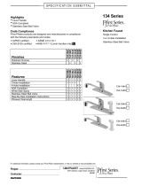
Fig. 4
1 Backplate
2 Adapter
3 Intermediate bushing
4 Additional diaphragms
5 Adapter plate
6 Metering diaphragm
7 Dosing head
8 Fixing bolt
9 Diaphragm rupture sensor
10 Feed channel
CAUTION!
Only above approximately 2 bar system back pres‐
sure is an electrical signal triggered in the event of
diaphragm rupture.
CAUTION!
Once the operating membrane has ruptured, a pre‐
cise metering rate can no longer be guaranteed.
5.5 Metering rate
The stroke length can be continuously adjusted between 100 %
and 10 % using the stroke length control knob (14).
The stroke rate control knob (16) can be used to manually set 0 to
110 (120) strokes/min.
Functional description
16

5.6 Control types
(Identity code characteristic "Control type": 0)
The controlling pulse is internally generated and adjusted using the
stroke rate control knob (16).
(Identity code characteristic "Control type": 1, 4):
The controlling pulse is externally generated from potential-free or
semiconductor contacts and fed to the drive unit via the "external
control" jack. Examples are contact water meter or controls.
(Identity code characteristic "Control type": 2, 3, 5, 6):
An external, analogue signal is fed to the drive unit via the
"External control” jack, the stroke rate changes proportionally
according to the 0 .. 20 mA or 4 .. 20 mA signal.
(Identity code characteristic "Control type": 7, 8):
As for "Internal stroke rate setting” version, however there is also
the possibility of switching the metering on and off via an external
semiconductor contact or potential-free contact.
All control types, that can be controlled via an
input, can be supplied with an "External control"
input of a "non-intrinsically safe" [i, a] or "intrinsi‐
cally safe" type.
5.7 Button for maximum stroke rate
(Identity code characteristic "Control variant": 1):
A push-button is available as an option to allow the pump to run at
maximum stroke rate.
(Identity code characteristic "Control variant": 2):
A key switch is available as an option to allow the pump to run at
maximum stroke rate.
”Internal stroke rate setting”
“External contact control”
"Analogue control x - 20 mA"
“Internal stroke rate setting with pause
function”
Push-button for max. frequency
Key switch for max. frequency
Functional description
17

6 Assembly
–
Compare the dimensions on the dimension
sheet with those of the pump.
WARNING!
Danger of electric shock
If water or other electrically conducting liquids pen‐
etrate into the drive housing, in any other manner
than via the pump's suction connection, an electric
shock may occur.
– Position the pump so that it cannot be flooded.
CAUTION!
Danger from incorrectly operated or inadequately
maintained pumps
Danger can arise from a poorly accessible pump
due to incorrect operation and poor maintenance.
– Ensure that the pump is accessible at all times.
–
Adhere to the maintenance intervals.
Capacity too low
The liquid end valves can be disturbed by vibra‐
tions.
–
Secure the metering pump so that no vibra‐
tions can occur.
Capacity too low
If the valves of the liquid end are not vertical, they
cannot close correctly.
–
Suction and discharge valves must stand verti‐
cally upwards (for self-bleeding liquid end, the
bleed valve).
Mount the metering pump with the pump foot on a horizontal,
level and load-bearing supporting surface.
Assembly
18

7 Installation, hydraulic
WARNING!
EX pumps in areas at risk of explosion
– Metering pumps in areas at risk of explosion
are provided, as a matter of course, with an
appropriate safety relief valve on the outlet side
of the metering pump (which is used to protect
against excessive heating due to overloading
and impact sparks caused by the breakage of
power end parts triggered by overloading.)
–
Should the various components have differing
temperature classes, scope for using the com‐
plete pump depends on the component with
the lowest temperature class.
– The version with an Ex”i” version of diaphragm
rupture sensor should always be used.
– Ensure that installations in areas at risk of
explosion are checked by a "recognised com‐
petent" person.
– Please note the relevant national regulations
during installation!
WARNING!
Risk of fire with flammable feed chemicals
– Flammable media may only be transported
using stainless steel dosing heads. In excep‐
tional cases where this is not possible, PTFE
with carbon can be used, whereby our TT_ ver‐
sions are manufactured from this conducting
plastic. Here, the operator is urged to take spe‐
cial care due to the low mechanical strength.
–
The metering pumps may meter flammable
media, but only in principle versions with the
“intrinsically safe [i,a]" version of the diaphragm
rupture sensor.
– The following applies to all metering pumps for
metering flammable media:
During filling and draining of the liquid end, an
expert must ensure that feed chemical does
not come into contact with air.
WARNING!
Warning of feed chemical reactions to water
Feed chemicals that should not come into contact
with water may react to residual water in the liquid
end that may originate from works testing.
– Blow the liquid end dry with compressed air
through the suction connector.
–
Then flush the liquid end with a suitable
medium through the suction connector.
Installation, hydraulic
19

WARNING!
The following measures are beneficial when
working with highly aggressive or hazardous feed
chemicals:
– Install a bleed valve with recirculation in the
storage tank.
–
Install a shut-off valve on the discharge or suc‐
tion side.
CAUTION!
Warning of feed chemical spraying around
PTFE seals, which have already been used / com‐
pressed, can no longer reliably seal a hydraulic
connection.
– New, unused PTFE seals must always be
used.
CAUTION!
Suction problems are possible
The valves may no longer close properly with feed
chemicals with a particle size of greater than 0.3
mm.
– Install a suitable filter in the suction line.
CAUTION!
Warning of the discharge line rupturing
With a closed discharge line (e.g. from a clogged
discharge line or by closing a valve), the pressure
that the metering pump generates may reach sev‐
eral times more than the permissible pressure of
the system or the metering pump. This could lead
to lines rupturing resulting in dangerous conse‐
quences with aggressive or hazardous feed chemi‐
cals.
– Install a relief valve that limits the pressure of
the pump to the maximum permissible oper‐
ating pressure of the system.
CAUTION!
Uncontrolled flow of feed chemical
Feed chemical may press through a stopped
metering pump if there is back pressure.
– Use an injection valve or a vacuum breaker.
Installation, hydraulic
20
/