Rockwell Automation Allen-Bradley 5069-L450ERMW User manual

Type
User manual
Compact 5000 I/O Serial Module
Catalog Numbers 5069-SERIAL
User Manual
Original Instructions
Important User Information
Read this document and the documents listed in the additional resources section about installation, configuration, and
operation of this equipment before you install, configure, operate, or maintain this product. Users are required to
familiarize themselves with installation and wiring instructions in addition to requirements of all applicable codes, laws,
and standards.
Activities including installation, adjustments, putting into service, use, assembly, disassembly, and maintenance are
required to be carried out by suitably trained personnel in accordance with applicable code of practice.
If this equipment is used in a manner not specified by the manufacturer, the protection provided by the equipment may
be impaired.
In no event will Rockwell Automation, Inc. be responsible or liable for indirect or consequential damages resulting from
the use or application of this equipment.
The examples and diagrams in this manual are included solely for illustrative purposes. Because of the many variables and
requirements associated with any particular installation, Rockwell Automation, Inc. cannot assume responsibility or
liability for actual use based on the examples and diagrams.
No patent liability is assumed by Rockwell Automation, Inc. with respect to use of information, circuits, equipment, or
software described in this manual.
Reproduction of the contents of this manual, in whole or in part, without written permission of Rockwell Automation,
Inc., is prohibited.
Throughout this manual, when necessary, we use notes to make you aware of safety considerations.
Labels may also be on or inside the equipment to provide specific precautions.
WARNING: Identifies information about practices or circumstances that can cause an explosion in a hazardous
environment, which may lead to personal injury or death, property damage, or economic loss.
ATTENTION: Identifies information about practices or circumstances that can lead to personal injury or death, property
damage, or economic loss. Attentions help you identify a hazard, avoid a hazard, and recognize the consequence.
IMPORTANT Identifies information that is critical for successful application and understanding of the product.
SHOCK HAZARD: Labels may be on or inside the equipment, for example, a drive or motor, to alert people that dangerous
voltage may be present.
BURN HAZARD: Labels may be on or inside the equipment, for example, a drive or motor, to alert people that surfaces may
reach dangerous temperatures.
ARC FLASH HAZARD: Labels may be on or inside the equipment, for example, a motor control center, to alert people to
potential Arc Flash. Arc Flash will cause severe injury or death. Wear proper Personal Protective Equipment (PPE). Follow ALL
Regulatory requirements for safe work practices and for Personal Protective Equipment (PPE).
Rockwell Automation Publication 5069-UM003B-EN-P - January 2020 3
Preface . . . . . . . . . . . . . . . . . . . . . . . . . . . . . . . . . . . . . . . . . . . . . . . . . . . . . . . .7
Summary of Changes . . . . . . . . . . . . . . . . . . . . . . . . . . . . . . . . . . . . . . . . . . . 7
Additional Resources . . . . . . . . . . . . . . . . . . . . . . . . . . . . . . . . . . . . . . . . . . . 8
Chapter 1
Compact 5000 I/O Serial Module
Overview
Controller and Software Compatibility . . . . . . . . . . . . . . . . . . . . . . . . . 10
Module Overview . . . . . . . . . . . . . . . . . . . . . . . . . . . . . . . . . . . . . . . . . . . . . 11
Local I/O or Remote I/O Modules . . . . . . . . . . . . . . . . . . . . . . . . . . . . . 12
Local I/O Modules . . . . . . . . . . . . . . . . . . . . . . . . . . . . . . . . . . . . . . . . 12
Remote I/O Module. . . . . . . . . . . . . . . . . . . . . . . . . . . . . . . . . . . . . . . 13
Chapter 2
Compact 5000 I/O Serial Module
Operation
Ownership . . . . . . . . . . . . . . . . . . . . . . . . . . . . . . . . . . . . . . . . . . . . . . . . . . . 15
Construct a System. . . . . . . . . . . . . . . . . . . . . . . . . . . . . . . . . . . . . . . . . . . . 16
Local I/O modules . . . . . . . . . . . . . . . . . . . . . . . . . . . . . . . . . . . . . . . . 16
Remote I/O modules . . . . . . . . . . . . . . . . . . . . . . . . . . . . . . . . . . . . . . 17
5069-ARM Address Reserve Module . . . . . . . . . . . . . . . . . . . . . . . . . . . 18
Power the Module. . . . . . . . . . . . . . . . . . . . . . . . . . . . . . . . . . . . . . . . . . . . . 19
5069-FPD Field Potential Distributor . . . . . . . . . . . . . . . . . . . . . . . . . . 20
Configure Modules. . . . . . . . . . . . . . . . . . . . . . . . . . . . . . . . . . . . . . . . . . . . 21
Connections . . . . . . . . . . . . . . . . . . . . . . . . . . . . . . . . . . . . . . . . . . . . . . 21
Chapter 3
Compact 5000 I/O Serial Module
Features
General. . . . . . . . . . . . . . . . . . . . . . . . . . . . . . . . . . . . . . . . . . . . . . . . . . . . . . . 25
Software Configurable . . . . . . . . . . . . . . . . . . . . . . . . . . . . . . . . . . . . . 25
Requested Packet Interval . . . . . . . . . . . . . . . . . . . . . . . . . . . . . . . . . . 26
Fault and Status Reporting . . . . . . . . . . . . . . . . . . . . . . . . . . . . . . . . . 27
Module Inhibiting. . . . . . . . . . . . . . . . . . . . . . . . . . . . . . . . . . . . . . . . . 27
Electronic Keying. . . . . . . . . . . . . . . . . . . . . . . . . . . . . . . . . . . . . . . . . . 28
Status Indicators . . . . . . . . . . . . . . . . . . . . . . . . . . . . . . . . . . . . . . . . . . 29
Module Firmware . . . . . . . . . . . . . . . . . . . . . . . . . . . . . . . . . . . . . . . . . 29
Common Module Functions . . . . . . . . . . . . . . . . . . . . . . . . . . . . . . . 30
Control Line Menu. . . . . . . . . . . . . . . . . . . . . . . . . . . . . . . . . . . . . . . . 31
Generic ASCII Data Exchange . . . . . . . . . . . . . . . . . . . . . . . . . . . . . . . . . 31
Data Sent with the Serial Port . . . . . . . . . . . . . . . . . . . . . . . . . . . . . . 31
Generic ASCII Transmit Functions. . . . . . . . . . . . . . . . . . . . . . . . . 32
Generic ASCII Transmit Methods. . . . . . . . . . . . . . . . . . . . . . . . . . 32
Data Received from the Serial Port. . . . . . . . . . . . . . . . . . . . . . . . . . 33
Generic ASCII Receive Functions . . . . . . . . . . . . . . . . . . . . . . . . . . 35
Generic ASCII Receive Methods . . . . . . . . . . . . . . . . . . . . . . . . . . . 36
Modbus Master Data Exchange . . . . . . . . . . . . . . . . . . . . . . . . . . . . . . . . 36
Modbus Master Functions . . . . . . . . . . . . . . . . . . . . . . . . . . . . . . . . . 37
Command Disable function . . . . . . . . . . . . . . . . . . . . . . . . . . . . . . . . 38
Modbus Slave Data Exchange . . . . . . . . . . . . . . . . . . . . . . . . . . . . . . . . . . 39
Modbus Slave Functions . . . . . . . . . . . . . . . . . . . . . . . . . . . . . . . . . . . 40
4 Rockwell Automation Publication 5069-UM003B-EN-P - January 2020
Table of Contents
DF1 Protocols . . . . . . . . . . . . . . . . . . . . . . . . . . . . . . . . . . . . . . . . . . . . . . . . 41
Using Modems that Support DF1 Communication Protocols. 41
Modem Control Line Operation . . . . . . . . . . . . . . . . . . . . . . . . . . . 43
Configuration Considerations for RTS Send and Off Delays . . 45
DF1 Point-to-Point Protocol . . . . . . . . . . . . . . . . . . . . . . . . . . . . . . . 46
DF1 Master Protocol . . . . . . . . . . . . . . . . . . . . . . . . . . . . . . . . . . . . . . 47
Configuring a Master Station for Standard Polling Mode . . . . . 47
Minimum DF1 Half-Duplex Master ACK Timeout. . . . . . . . . . 51
Determining Minimum Master Serial Port ACK Timeout . . . . 51
Create Polling Lists . . . . . . . . . . . . . . . . . . . . . . . . . . . . . . . . . . . . . . . . 53
Monitor Active Stations . . . . . . . . . . . . . . . . . . . . . . . . . . . . . . . . . . . 54
Configuring a Message-Based Mode
DF1 Half-Duplex Master Station . . . . . . . . . . . . . . . . . . . . . . . . . . . 54
Configuring a Master Station for Message-based Polling Mode 55
DF1 Slave Protocol . . . . . . . . . . . . . . . . . . . . . . . . . . . . . . . . . . . . . . . . 59
Configuring the Controller as a Slave Station . . . . . . . . . . . . . . . . 59
DF1 Radio Modem Protocol . . . . . . . . . . . . . . . . . . . . . . . . . . . . . . . 61
Designing Communication for DF1 Radio Modem Protocol. . 62
DF1 Data Exchange . . . . . . . . . . . . . . . . . . . . . . . . . . . . . . . . . . . . . . . . . . . 65
DF1 Point to Point Parameters . . . . . . . . . . . . . . . . . . . . . . . . . . . . . 66
DF1 Master Parameters . . . . . . . . . . . . . . . . . . . . . . . . . . . . . . . . . . . . 66
DF1 Slave Parameters. . . . . . . . . . . . . . . . . . . . . . . . . . . . . . . . . . . . . . 67
DF1 Radio Modem Parameters . . . . . . . . . . . . . . . . . . . . . . . . . . . . . 67
DH-485 Data Exchange . . . . . . . . . . . . . . . . . . . . . . . . . . . . . . . . . . . . . . . 68
DH-485 Functions. . . . . . . . . . . . . . . . . . . . . . . . . . . . . . . . . . . . . . . . 69
Chapter 4
Compact 5000 I/O Serial Module
Configuration
Before You Begin. . . . . . . . . . . . . . . . . . . . . . . . . . . . . . . . . . . . . . . . . . . . . . 71
Add a New Module . . . . . . . . . . . . . . . . . . . . . . . . . . . . . . . . . . . . . . . . . . . 72
Discover Local I/O Modules . . . . . . . . . . . . . . . . . . . . . . . . . . . . . . . 72
Discover Remote I/O Modules . . . . . . . . . . . . . . . . . . . . . . . . . . . . . 74
New Local I/O Modules . . . . . . . . . . . . . . . . . . . . . . . . . . . . . . . . . . . 76
New Remote I/O Module. . . . . . . . . . . . . . . . . . . . . . . . . . . . . . . . . . 78
Edit the Module Configuration . . . . . . . . . . . . . . . . . . . . . . . . . . . . . . . . 80
General Category. . . . . . . . . . . . . . . . . . . . . . . . . . . . . . . . . . . . . . . . . . 80
Connection Category. . . . . . . . . . . . . . . . . . . . . . . . . . . . . . . . . . . . . . 89
Module Info Category . . . . . . . . . . . . . . . . . . . . . . . . . . . . . . . . . . . . 104
View the Module Tags. . . . . . . . . . . . . . . . . . . . . . . . . . . . . . . . . . . . . . . . 105
Rockwell Automation Publication 5069-UM003B-EN-P - January 2020 5
Table of Contents
Chapter 5
Troubleshoot Your Module Module Status Indicator . . . . . . . . . . . . . . . . . . . . . . . . . . . . . . . . . . . . . . 107
Compact 5000 I/O Serial Module Status Indicators. . . . . . . . . . . . . 108
Appendix A
Module Tags Name Conventions . . . . . . . . . . . . . . . . . . . . . . . . . . . . . . . . . . . . . . . . . . 109
Generic ASCII and Modbus Slave Name Conventions . . . . . . 109
Modbus Master Name Conventions . . . . . . . . . . . . . . . . . . . . . . . 110
DF1 Name Conventions . . . . . . . . . . . . . . . . . . . . . . . . . . . . . . . . . . 110
DH-485 Name Conventions . . . . . . . . . . . . . . . . . . . . . . . . . . . . . . 110
Access the Tags . . . . . . . . . . . . . . . . . . . . . . . . . . . . . . . . . . . . . . . . . . . . . . 111
Channel Configured Generic ASCII Tags. . . . . . . . . . . . . . . . . . . . . . 112
Channel Configured for Generic ASCII . . . . . . . . . . . . . . . . . . . . . . . 113
Input Tags . . . . . . . . . . . . . . . . . . . . . . . . . . . . . . . . . . . . . . . . . . . . . . . 113
Output Tags . . . . . . . . . . . . . . . . . . . . . . . . . . . . . . . . . . . . . . . . . . . . . 116
Channel Configured for Modbus Master. . . . . . . . . . . . . . . . . . . . . . . 117
Input Tags . . . . . . . . . . . . . . . . . . . . . . . . . . . . . . . . . . . . . . . . . . . . . . . 117
Output Tags . . . . . . . . . . . . . . . . . . . . . . . . . . . . . . . . . . . . . . . . . . . . . 119
Channel Configured for Modbus Slave. . . . . . . . . . . . . . . . . . . . . . . . . 120
Input Tags . . . . . . . . . . . . . . . . . . . . . . . . . . . . . . . . . . . . . . . . . . . . . . . 121
Output Tags . . . . . . . . . . . . . . . . . . . . . . . . . . . . . . . . . . . . . . . . . . . . . 122
Channel Configured for DF1—Point to Point . . . . . . . . . . . . . . . . . 123
Input Tags . . . . . . . . . . . . . . . . . . . . . . . . . . . . . . . . . . . . . . . . . . . . . . . 124
Output Tags . . . . . . . . . . . . . . . . . . . . . . . . . . . . . . . . . . . . . . . . . . . . . 124
Channel Configured for DF1—Master . . . . . . . . . . . . . . . . . . . . . . . . 125
Input Tags . . . . . . . . . . . . . . . . . . . . . . . . . . . . . . . . . . . . . . . . . . . . . . . 126
Output Tags . . . . . . . . . . . . . . . . . . . . . . . . . . . . . . . . . . . . . . . . . . . . . 126
Channel Configured for DF1—Slave . . . . . . . . . . . . . . . . . . . . . . . . . . 127
Input Tags . . . . . . . . . . . . . . . . . . . . . . . . . . . . . . . . . . . . . . . . . . . . . . . 127
Channel Configured for DF1—Radio Modem . . . . . . . . . . . . . . . . . 128
Input Tags . . . . . . . . . . . . . . . . . . . . . . . . . . . . . . . . . . . . . . . . . . . . . . . 128
Output Tags . . . . . . . . . . . . . . . . . . . . . . . . . . . . . . . . . . . . . . . . . . . . . 128
Channel Configured for DH-485 . . . . . . . . . . . . . . . . . . . . . . . . . . . . . 129
Input Tags . . . . . . . . . . . . . . . . . . . . . . . . . . . . . . . . . . . . . . . . . . . . . . . 129
6 Rockwell Automation Publication 5069-UM003B-EN-P - January 2020
Table of Contents
Appendix B
Modbus Command Codes Master Command List Function Codes . . . . . . . . . . . . . . . . . . . . . . . . 131
Read Coil Status (Function Code 01) . . . . . . . . . . . . . . . . . . . . . . 131
Read Input Status (Function Code 02) . . . . . . . . . . . . . . . . . . . . . 133
Read Holding Registers (Function Code 03). . . . . . . . . . . . . . . . 134
Read Input Registers (Function Code 04) . . . . . . . . . . . . . . . . . . 135
Force Single Coil (Function Code 05). . . . . . . . . . . . . . . . . . . . . . 136
Preset Single Register (Function Code 06) . . . . . . . . . . . . . . . . . . 138
Force Multiple Coils (Function Code 15) . . . . . . . . . . . . . . . . . . 139
Preset Multiple Registers (Function Code 16) . . . . . . . . . . . . . . 140
Appendix C
Programming Example Generic ASCII Sample Code. . . . . . . . . . . . . . . . . . . . . . . . . . . . . . . . . . 141
Transmit and Receive Channel Configurations . . . . . . . . . . . . . 141
Sample Code. . . . . . . . . . . . . . . . . . . . . . . . . . . . . . . . . . . . . . . . . . . . . 142
Modbus Sample Code Configuration . . . . . . . . . . . . . . . . . . . . . . . . . . 144
Modbus Master Command List. . . . . . . . . . . . . . . . . . . . . . . . . . . . 144
Modbus Slave Address Mapping Table . . . . . . . . . . . . . . . . . . . . . 144
Modbus Sample Code Configuration Example. . . . . . . . . . . . . . 144
Modbus Master Sample Code . . . . . . . . . . . . . . . . . . . . . . . . . . . . . . . . . 145
Modbus Slave Sample Code . . . . . . . . . . . . . . . . . . . . . . . . . . . . . . . . . . . 145
Example MSG Control Blocks . . . . . . . . . . . . . . . . . . . . . . . . . . . . . . . . 147
Appendix D
ASCII Conversion Tables ASCII Conversions . . . . . . . . . . . . . . . . . . . . . . . . . . . . . . . . . . . . . . . . . . 151
Index . . . . . . . . . . . . . . . . . . . . . . . . . . . . . . . . . . . . . . . . . . . . . . . . . . . . . . .153
Rockwell Automation Publication 5069-UM003B-EN-P - January 2020 7
Preface
This manual describes how to use Compact 5000â„¢ I/O serial module in
Logix 5000â„¢ systems.
Make sure that you are familiar with the following:
• Use of a Logix 5000™ controller
• Use of an EtherNet/IP™ network, if the serial module is installed in a
remote location that is accessible via the EtherNet/IP network.
• Studio 5000 Logix Designer® environment.
Summary of Changes
IMPORTANT The Compact 5000 I/O Serial module is only compatible with the
following controllers:
• CompactLogix™ 5380
• Compact GuardLogix® 5380
• CompactLogix 5480
• ControlLogix® 5580
• GuardLogix® 5580
Topic Page
Moved Controller software from operation chapter to overview chapter 12
Added Compact 5000 I/O modules table 12
Added Types of modules 13
Moved Local I/O or Remote I/O modules from operation chapter to overview chapter 15
Updated Construct a System topic with new text 18
Moved 5069-ARM Address Reserve Module after Construct a System 20
Updated Additional information for Compact 5000 I/O modules 21
Moved 5069-FPD Field Potential Distributor after Power the Module 22
Updated Additional information for Compact 5000 I/O modules 22
Moved Modbus Master Functions under Modbus Master Data Exchange 38
Added DF1 protocols 41
Added DF1 Data Exchange 44
Added DH-485 Data Exchange 45
Added DF1 Parameters 72
Added DH-485 Parameters 80
Added channel configuration for DF1 Point to Point 101
Added channel configuration for DF1 Master 103
Added channel configuration for DF1 Slave 105
Added channel configuration for DF1 Radio Modem 106
Added channel configuration for DH-485 107
Added DF1 sample code configuration 135
8 Rockwell Automation Publication 5069-UM003B-EN-P - January 2020
Preface
Additional Resources
These documents contain additional information concerning related products
from Rockwell Automation.
You can view or download publications at
http://www.rockwellautomation.com/global/literature-library/overview.page
.
Resource Description
Compact 5000 I/O Serial Module Install Instructions,
publication 5069-IN022
Describes how to install the Compact 5000 I/O Serial
Module.
5069 Compact I/O EtherNet/IP Adapter Installation
Instructions, publication 5069-IN003
Describes how to install and wire the
Compact 5000 I/O EtherNet/IP adapters.
Compact 5000 I/O Modules Specifications Technical Data,
publication 5069-TD001
Provides specifications, wiring diagrams, and module
block diagrams Compact 5000 I/O modules
5000 Series I/O Modules in Logix5000 Control Systems User
Manual, publication 5000-UM004
Describes how to use 5000 Series I/O modules.
5000 Series Analog I/O Modules in Logix 5000 Control
Systems User Manual, publication 5000-UM005
Describes how to use Compact 5000 I/O analog
modules.
5000 Series High-speed Counter Modules in Logix 5000
Control Systems User Manual, publication 5000-UM006
Describes how to use the Compact 5000 I/O.
EtherNet/IP Communication Modules in 5000 Series
Control Systems User Manual, publication ENET-UM004
Describes how to use Compact 5000 I/O EtherNet/IP
adapters.
CompactLogix 5380 and Compact GuardLogix 5380
Controllers User Manual, publication 5069-UM001
Describes how to use CompactLogix 5380 and
Compact GuardLogix 5380 controllers.
ControlLogix 5580 and GuardLogix 5580 Controllers User
Manual, publication 1756-UM543
Describes how to use ControlLogix 5580 and
GuardLogix 5580 controllers.
Electronic Keying in Logix 5000 Control Systems
Application Technique, publication LOGIX-AT001
Describes how to use electronic keying in Logix 5000
control system applications.
DF1 Protocol and Command Set Reference Manual,
publication 1770-RM516
Describes how to use electronic keying in Logix 5000
control system applications.
SCADA System Application Guide, publication AG-UM008 Application guide for SCADA systems.
ControlLogix DH-485 Communication Module,
publication
1756-UM532
Describes how to use the ControlLogix DH-485
Communication Module.
Industrial Automation Wiring and Grounding Guidelines,
publication 1770-4.1
Provides general guidelines for installing a Rockwell
Automation industrial system.
Product Certifications website: rok.auto/certifications Provides declarations of conformity, certificates, and
other certification details.
Rockwell Automation Publication 5069-UM003B-EN-P - January 2020 9
Chapter 1
Compact 5000 I/O Serial Module Overview
The Compact 5000â„¢ I/O serial module provides two independent channels
that function as network interface via RS232C, RS422 or RS485 to serial
devices communicating on Generic ASCII, Modbus RTU/ASCII, DF1 or
DH-485 protocol.
The module has two channels that are independent of each other. The channels
can transmit data to and receive data from serial devices using the following
communication mode:
• Generic ASCII
• Modbus RTU/ASCII (Master/Slave)
•DF1
• DH-485
The serial module can reside locally in a CompactLogixâ„¢ 5380, Compact
GuardLogix® 5380, or CompactLogix™ 5480 system. The module can also reside
in a remote Compact 5000 I/O system accessible via an EtherNet/IPâ„¢ network.
Topic Page
Controller and Software Compatibility 10
Module Overview 11
Local I/O or Remote I/O Modules 12
IMPORTANT Use Studio 5000 Logix Designer® Version 31 or greater. You must install an
Add-On Profile to use the serial module. To find the Add-On Profile, go to the
Product Compatibility and Download Center
(PCDC).
DF1 and DH-485 must use Channel 1 and be local.
The serial module with firmware revision 2.011 and later with Add-On
profile version 2.01 supports DH-485 and DF1 protocols DF1 Point to Point,
DF1 Master, DF1 Slave, and DF1 Radio modem.
10 Rockwell Automation Publication 5069-UM003B-EN-P - January 2020
Chapter 1 Compact 5000 I/O Serial Module Overview
Controller and Software
Compatibility
When you use Compact 5000â„¢ I/O serial module in Logix 5000â„¢ controller
control system, the Compact 5000 I/O Serial module is compatible with the
following controllers:
• CompactLogix™ 5380
• Compact GuardLogix® 5380
• CompactLogix™ 5480
• ControlLogix® 5580 (remote only)
•GuardLogix® 5580 (remote only)
IMPORTANT The serial module is not compatible with the 5069-AEN2TR. See the Product
Compatibility and Download Center (PCDC) for more information.
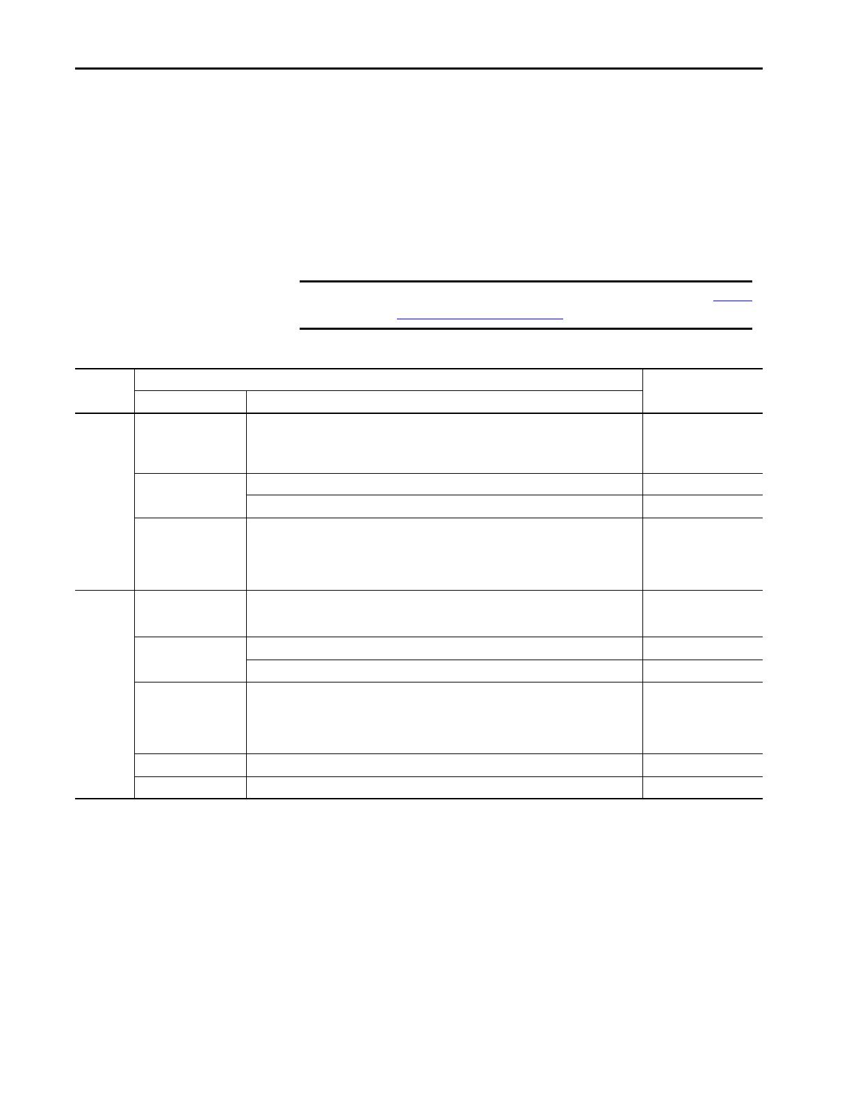
Table 1 - Compact 5000 I/O Modules Controller and Software Compatibility Requirements
Location
Controllers
Logix Designer
ApplicationSystem Cat. Nos.
Local I/O
modules
CompactLogix 5380 5069-L320ER, 5069-L320ERMK, 5069-L330ERMK, 5069-L340ERM, 5069-L350ERMK, 5069-L306ER,
5069-L306ERM, 5069-L310ER, 5069-L310ERM, 5069-L310ER-NSE, 5069-L310ERS2, 5069-L320ERM,
5069-L320ERMK, 5069-L330ER, 5069-L330ERM, 5069-L330ERMK, 5069-L340ER, 5069-L350ERM,
5069-L350ERMK, 5069-L380ERM, 5069-L3100ERM
Version 31.00.00 or later
CompactLogix 5480
5069-L46ERMW Version 32.00.00 or later
5069-L430ERMW, 5069-L450ERMW, 5069-L4100ERMW, 5069-L4200ERMW Version 32.01.00 or later
Compact GuardLogix 5380 5069-L306ERS2, 5069-L306ERMS2, 5069-L310ERS2, 5069-L310ERMS2, 5069-L320ERS2,
5069-L320ERS2K, 5069-L320ERMS2, 5069-L320ERMS2K, 5069-L330ERS2, 5069-5069-L330ERS2K,
L330ERMS2, 5069-L330ERMS2K, 5069-L340ERS2, 5069-L340ERMS2, 5069-L350ERS2,
5069-L350ERS2K, 5069-L350ERMS2, 5069-L350ERMS2K, 5069-L380ERS2, 5069-L380ERMS2,
5069-L3100ERS2, 5069-L3100ERMS2
Version 31.00.00 or later
Remote I/O
modules
(1)
CompactLogix 5380 5069-L320ER, 5069-L340ERM, 5069-L306ER, 5069-L306ERM, 5069-L310ER, 5069-L310ERM, 5069-
L310ER-NSE, 5069-L310ERS2, 5069-L320ERM, 5069-L330ER, 5069-L330ERM, 5069-L340ER, 5069-
L350ERM, 5069-L380ERM, 5069-L3100ERM
Version 31.00.00 or later
CompactLogix 5480
5069-L46ERMW Version 32.00.00 or later
5069-L430ERMW, 5069-L450ERMW, 5069-L4100ERMW, 5069-L4200ERMW Version 32.01.00 or later
Compact GuardLogix 5380 5069-L306ERS2, 5069-L306ERMS2, 5069-L310ERS2, 5069-L310ERMS2, 5069-L320ERS2,
5069-L320ERS2K, 5069-L320ERMS2, 5069-L320ERMS2K, 5069-L330ERS2, 5069-5069-L330ERS2K,
L330ERMS2, 5069-L330ERMS2K, 5069-L340ERS2, 5069-L340ERMS2, 5069-L350ERS2,
5069-L350ERS2K, 5069-L350ERMS2, 5069-L350ERMS2K, 5069-L380ERS2, 5069-L380ERMS2,
5069-L3100ERS2, 5069-L3100ERMS2
Version 31.00.00 or later
ControlLogix® 5580 1756-L83E, 1756-L85E, 1756-L81E, 1756-L82E, 1756-L84E Version 31.00.00 or later
GuardLogix 5580 1756-L81ES, 1756-L82ES, 1756-L83ES, 1756-L84ES Version 31.00.00 or later
(1) Serial module is not compatible with 5069-AEN2TR.
Rockwell Automation Publication 5069-UM003B-EN-P - January 2020 11
Compact 5000 I/O Serial Module Overview Chapter 1
Module Overview
The module provides the communication connections to the serial devices.
Figure 1 - Example Compact 5000 I/O Serial Module
 
2
1
5
6
3
4
6
5
Table 2 - Compact 5000 I/O Serial Module Parts
Item Item Name Description
1 Status Indicators Displays the status of communication, module health, and input/output
devices. Indicators help with troubleshooting anomalies.
2 Interlocking side pieces Securely installs Compact 5000 I/O serial modules in the system.
3 DIN rail latch Secures the module on the DIN rail.
4 MOD Power bus and SA
Power bus connectors
Pass system-side and field-side power across the internal circuitry of the I/O
modules in a Compact 5000 I/O system. The connectors are isolated from
each other.
5 Channel 0 Channel 0 isolated serial port.
6 Channel 1 Channel 1 isolated serial port.
12 Rockwell Automation Publication 5069-UM003B-EN-P - January 2020
Chapter 1 Compact 5000 I/O Serial Module Overview
Local I/O or Remote
I/O Modules
You can use Compact 5000 I/O modules as local or remote
I/O modules, with some restrictions that are based on the module and controller
type. Compatibility requirements apply and are described in Controller and
Software Compatibility on page 10.
Local I/O Modules
When Compact 5000 I/O Serial module resides in the same system as the
controller, it is a local I/O module. Local I/O modules are installed to the right of
the controller and exchange data with the controller over the system backplane.
Figure 2 - Compact 5000 I/O Serial Module as Local I/O Module
IMPORTANT Compact 5000 I/O Serial modules can function as local I/O modules in
the following:
• CompactLogix 5380 control systems
• Compact GuardLogix 5380 control systems
• CompactLogix 5480 control systems
 
CompactLogix 5380 Controller
Local Compact 5000 I/O Standard Modules
Rockwell Automation Publication 5069-UM003B-EN-P - January 2020 13
Compact 5000 I/O Serial Module Overview Chapter 1
Remote I/O Module
When a Compact 5000 I/O Serial module resides in a separate location from the
controller, it is a remote I/O module. Remote Compact 5000 I/O modules are
accessible over an EtherNet/IP network via a Compact 5000 EtherNet/IP
adapter.
Remote Compact 5000 I/O modules are installed to the right of the adapter and
exchange data across the remote system backplane. The data is exchanged with
the controller over the EtherNet/IP network.
Figure 3 - Compact 5000 I/O Serial Module as Remote I/O Module
IMPORTANT Compact 5000 I/O Serial modules can function as remote I/O modules in
the following:
• CompactLogix 5380 control systems
• Compact GuardLogix 5380 control systems
• CompactLogix 5480 control systems
• ControlLogix 5580 control systems
• GuardLogix 5580 control systems
DF1 and DH-485 modes are not supported remotely.
 
 
 
PanelViewâ„¢ Plus 7 Terminal
CompactLogix 5380 Controller
Compact 5000 I/O Modules
Compact 5000 EtherNet/IP Adapter
Compact 5000 I/O Modules
PowerFlex
® 527 Drive
Compact 5000 I/O Modules
Stratix 5400 Switch
14 Rockwell Automation Publication 5069-UM003B-EN-P - January 2020
Chapter 1 Compact 5000 I/O Serial Module Overview
Notes:
Rockwell Automation Publication 5069-UM003B-EN-P - January 2020 15
Chapter 2
Compact 5000 I/O Serial Module Operation
Ownership
Every I/O module in a Logix 5000â„¢ control system must be owned by a
controller, also known as the owner-controller. When the Compact 5000 I/O
modules are used in a Logix 5000 control system, the owner-controller performs
the following:
• Stores configuration data for every module that it owns.
• Can reside in a location that differs from the Compact 5000 I/O modules.
• Sends the I/O module configuration data to define module behavior and
begin operation in the control system.
Each Compact 5000 I/O serial module must continuously maintain
communication with its owner-controller during normal operation.
Topic Page
Ownership 15
Construct a System 16
5069-ARM Address Reserve Module 18
Power the Module 19
5069-FPD Field Potential Distributor 20
Configure Modules 21
16 Rockwell Automation Publication 5069-UM003B-EN-P - January 2020
Chapter 2 Compact 5000 I/O Serial Module Operation
Construct a System
Before you use your serial module, you must complete tasks based on whether the
modules are local or remote I/O modules:
Local I/O modules
Complete the following steps.
1. Install a CompactLogixâ„¢ 5380, CompactLogix 5480, or
Compact GuardLogix® 5380 controller.
2. Install the modules to the right of the controller.
3. Install the end cap on the last module in the system.
IMPORTANT You must use a Compact GuardLogix 5380 controller if the
local Compact 5000 I/O modules include safety modules.
For more information on controller compatibility,
see Controller and Software Compatibility on page 10
.
IMPORTANT The end cap in a CompactLogix 5380, CompactLogix 5480, or
Compact GuardLogix 5380 control system covers the exposed
interconnection on the last module on the DIN rail.
If you do not install an end cap on the last module on the DIN rail,
equipment damage or injury can occur.
Rockwell Automation Publication 5069-UM003B-EN-P - January 2020 17
Compact 5000 I/O Serial Module Operation Chapter 2
Remote I/O modules
Complete the following:
1. Install a controller that is compatible with the remote Compact 5000
I/O modules.
2. Install an EtherNet/IPâ„¢ network.
3. Connect the controller to the network.
4. Install a Compact 5000 EtherNet/IP adapter.
5. Connect the adapter to the network.
6. Install the Compact 5000 I/O modules to the right of the adapter.
7. Install the end cap on the last module in the system.
IMPORTANT Remember, you must use a Compact GuardLogix 5380
controller or GuardLogix 5580 controller if the set of remote
Compact 5000 I/O modules include safety modules.
For more information on controller compatibility,
see Controller and Software Compatibility on page 10
.
IMPORTANT If serial module is included, you must use AENTR
IMPORTANT The end cap in a CompactLogix 5380, CompactLogix 5480, or
Compact GuardLogix 5380 control system covers the exposed
interconnection on the last module on the DIN rail.
If you do not install an end cap on the last module on the DIN rail,
equipment damage or injury can occur.
18 Rockwell Automation Publication 5069-UM003B-EN-P - January 2020
Chapter 2 Compact 5000 I/O Serial Module Operation
5069-ARM Address
Reserve Module
Every Compact 5000 I/O module has a unique node address in a system. As
modules are installed, the node addresses increment. The Logix Designer
application project includes modules in the I/O Configuration that correspond
to the physical modules.
If a module is not available during initial system installation and operation, you
can use a 5069-ARM address reserve module to reserve the slot in the system.
That is, you install the 5069-ARM address reserve module to reserve the node
address. The address reserve module remains installed until the I/O module is
available.
When you install the address reserve module, you also make sure that the
subsequently-installed modules are at the correct node address.
You use the corresponding entry in the Logix Designer application project to
reserve the node address. That is, when you add modules to the I/O
Configuration tree in the project, you add an address reserve module at the node
address that matches the physical module location.
Figure 4 - Compact 5000 I/O System with 5069-ARM Address Reserve Module
5069-ARM Address Reserve Module
 
Rockwell Automation Publication 5069-UM003B-EN-P - January 2020 19
Compact 5000 I/O Serial Module Operation Chapter 2
Power the Module
Compact 5000 I/O modules receive the following power types from first
component in the system, that is, the controller or adapter:
• System-side Power - Powers the system and lets modules transfer data and
execute logic.
System-side power is provided through the Module (MOD) Power
connector and is passed to each module as it is added to the system.
System-side power is also known as MOD power.
• Field-side Power - Powers field-side devices that are connected to some
Compact 5000 I/O modules.
Field-side power is provided through the Sensor/Actuator (SA) Power
connector and is passed to each module as it is added to the system.
Field-side power is also known as SA power.
Power begins at the left-most device in the system and passes across the Compact
5000 I/O module internal circuitry via power buses, that is, a MOD power bus.
The left-most device is either a controller or an EtherNet/IP adapter, depending
on whether the Serial module is a local or remote I/O module.
For more information on how to power local Compact 5000 I/O modules, see
the following:
• CompactLogix 5380 and Compact GuardLogix 5380 Controllers User
Manual, publication 5069-UM001
• CompactLogix 5480 Controller User Manual, publication 5069-UM002
For more information on how to power remote Compact 5000 I/O
modules, see the Compact 5000 EtherNet/IP Adapters User Manual,
publication 5069-UM007
.
IMPORTANT The Compact 5000 I/O Serial Module does not use SA power.
However, verify that the module is installed in a position where
SA power uses DC voltage.
IMPORTANT Remember the following:
• A system uses only one MOD power bus that starts at a
controller or adapter and passes across all modules that are
installed in the system.
• A system can use multiple SA power bus. The first SA power bus
typically starts at the controller or adapter, and
5069-FPD field potential distributors let you establish new SA
power buses in the same system.
20 Rockwell Automation Publication 5069-UM003B-EN-P - January 2020
Chapter 2 Compact 5000 I/O Serial Module Operation
5069-FPD Field
Potential Distributor
The controller or adapter, based on whether the module is a local or
remote I/O module, is the primary source of field-side power, that is, SA power,
in the system. However, you can use a 5069-FPD field potential distributor to
break field-side power distribution in a system and establish a new SA power bus.
Field-side power passes across the internal circuitry of the Compact 5000 I/O
modules beginning with the controller or the adapter. The field potential
distributor blocks the passage of field-side power from the left and functions as a
new field-side power source for the modules to the right.
Figure 5 - Compact 5000 I/O System with 5069-FPD Field Potential Distributor
For more information on how to power local Compact 5000 I/O modules, see
the following:
• CompactLogix 5380 and Compact GuardLogix 5380 Controllers User
Manual, publication 5069-UM001
• CompactLogix 5480 Controller User Manual, publication 5069-UM002
For more information on how to power remote Compact 5000 I/O
modules, see the Compact 5000 EtherNet/IP Adapters User Manual,
publication 5069-UM007
.
 
  • Page 1 1
  • Page 2 2
  • Page 3 3
  • Page 4 4
  • Page 5 5
  • Page 6 6
  • Page 7 7
  • Page 8 8
  • Page 9 9
  • Page 10 10
  • Page 11 11
  • Page 12 12
  • Page 13 13
  • Page 14 14
  • Page 15 15
  • Page 16 16
  • Page 17 17
  • Page 18 18
  • Page 19 19
  • Page 20 20
  • Page 21 21
  • Page 22 22
  • Page 23 23
  • Page 24 24
  • Page 25 25
  • Page 26 26
  • Page 27 27
  • Page 28 28
  • Page 29 29
  • Page 30 30
  • Page 31 31
  • Page 32 32
  • Page 33 33
  • Page 34 34
  • Page 35 35
  • Page 36 36
  • Page 37 37
  • Page 38 38
  • Page 39 39
  • Page 40 40
  • Page 41 41
  • Page 42 42
  • Page 43 43
  • Page 44 44
  • Page 45 45
  • Page 46 46
  • Page 47 47
  • Page 48 48
  • Page 49 49
  • Page 50 50
  • Page 51 51
  • Page 52 52
  • Page 53 53
  • Page 54 54
  • Page 55 55
  • Page 56 56
  • Page 57 57
  • Page 58 58
  • Page 59 59
  • Page 60 60
  • Page 61 61
  • Page 62 62
  • Page 63 63
  • Page 64 64
  • Page 65 65
  • Page 66 66
  • Page 67 67
  • Page 68 68
  • Page 69 69
  • Page 70 70
  • Page 71 71
  • Page 72 72
  • Page 73 73
  • Page 74 74
  • Page 75 75
  • Page 76 76
  • Page 77 77
  • Page 78 78
  • Page 79 79
  • Page 80 80
  • Page 81 81
  • Page 82 82
  • Page 83 83
  • Page 84 84
  • Page 85 85
  • Page 86 86
  • Page 87 87
  • Page 88 88
  • Page 89 89
  • Page 90 90
  • Page 91 91
  • Page 92 92
  • Page 93 93
  • Page 94 94
  • Page 95 95
  • Page 96 96
  • Page 97 97
  • Page 98 98
  • Page 99 99
  • Page 100 100
  • Page 101 101
  • Page 102 102
  • Page 103 103
  • Page 104 104
  • Page 105 105
  • Page 106 106
  • Page 107 107
  • Page 108 108
  • Page 109 109
  • Page 110 110
  • Page 111 111
  • Page 112 112
  • Page 113 113
  • Page 114 114
  • Page 115 115
  • Page 116 116
  • Page 117 117
  • Page 118 118
  • Page 119 119
  • Page 120 120
  • Page 121 121
  • Page 122 122
  • Page 123 123
  • Page 124 124
  • Page 125 125
  • Page 126 126
  • Page 127 127
  • Page 128 128
  • Page 129 129
  • Page 130 130
  • Page 131 131
  • Page 132 132
  • Page 133 133
  • Page 134 134
  • Page 135 135
  • Page 136 136
  • Page 137 137
  • Page 138 138
  • Page 139 139
  • Page 140 140
  • Page 141 141
  • Page 142 142
  • Page 143 143
  • Page 144 144
  • Page 145 145
  • Page 146 146
  • Page 147 147
  • Page 148 148
  • Page 149 149
  • Page 150 150
  • Page 151 151
  • Page 152 152
  • Page 153 153
  • Page 154 154
  • Page 155 155
  • Page 156 156

Rockwell Automation Allen-Bradley 5069-L450ERMW User manual

Type
User manual

Ask a question and I''ll find the answer in the document

Finding information in a document is now easier with AI