
RTF-TC
RTU-TC
RTF-TC
RTU-TC
• English
• Deutsch
• Français
• Suomi
• Polski
• Česky
INSTRUCTIONS
GREEN COMFORT
Maximum comfort with low energy consumption
• Svenska
• Nederlands
• Lietuvių k.
• Italiano
• Español
• Português
Page is loading ...

3© 2018 OJ Electronics A/S
RTF-TC
RTU-TC
© 2018 OJ Electronics A/S
ILLUSTRATIONS
Pages ....................................................................................3
INSTRUCTIONS
English .................................................................................. 7
Deutsch .............................................................................. 12
Français .............................................................................. 17
Suomi ................................................................................. 22
Polski .................................................................................. 27
Česky .................................................................................. 32
Svenska .............................................................................. 37
Nederlands ......................................................................... 42
Lietuvių k. ........................................................................... 47
Italiano ................................................................................ 52
Español ............................................................................... 57
Português ........................................................................... 62
BR1017A02
Fig. 1
Fig. 2
BR1017A01
BR1017A01BR1017A02

4 © 2018 OJ Electronics A/S © 2018 OJ Electronics A/S
RTF-TC / RTU-TC
BR1017A03A
1.5m
1
2
3
BR1017A03a
BR1017A05A
653 421
N
L
Fig. 3
Fig. 4
BR1017A04c

© 2018 OJ Electronics A/S 5© 2018 OJ Electronics A/S
RTF-TC / RTU-TC RTF-TC / RTU-TC
BR1017A03a
BR1017A05A
653 421
N
L
BR1017A06
Fig. 5
Fig. 6
BR1017A05aBR1017A06
BR1017A04c

© 2018 OJ Electronics A/S6 © 2018 OJ Electronics A/S
RTF-TC / RTU-TC
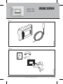
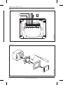
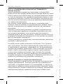
FIG. 1 - CONTENT
• Thermostat
• Sensor
The thermostat is an electronic PWM/PI thermostat for temperature
control by means of an NTC sensor located either externally or
internally within the thermostat.
The thermostat is for flush mounting in a wall socket. A baseplate
for wall mounting is also available.
This thermostat can be used as a controller for electric room heating
pursuant to EN50559.*
* Only valid for RTF-TC (MCD5-1999)
Product programme
RTF-TC (MCD5-1999) Clock-thermostat with two sensors:
floor sensor and built-in room sensor.
RTU-TC (MCC5-1999) Clock-thermostat with built-in room
sensor.
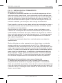
FIG. 2 - WARNING – Important Safety Instructions
Disconnect the power supply before carrying out any installation or
maintenance work on this thermostat and associated components.
The thermostat and associated components should only be installed
by a competent person (i.e. a qualified electrician). Electrical instal-
lation must be in accordance with appropriate statutory regulations.
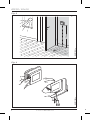
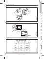
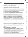
FIG. 3 - THERMOSTAT PLACEMENT
Mounting of sensor
The floor sensor contains a safety extra-low voltage (SELV) circuit,
allowing it to be placed as close to the floor surface as possible
without having to take account of the risk of shock should the sen-
sor cable become damaged. The two wires connecting the sensor
to the mounting box must be additionally insulated, e.g. shrink flex.
1
2
3
4
4
BR1017A14BR1017A07
Fig. 7
Fig. 8
BR1017A07
ON
OFF
1
2
Manual
Menu
Auto
BR1017A17
Fig. 9

7© 2018 OJ Electronics A/S
RTF-TC
RTU-TC
© 2018 OJ Electronics A/S
RTF-TC / RTU-TC
FIG. 1 - CONTENT
• Thermostat
• Sensor
The thermostat is an electronic PWM/PI thermostat for temperature
control by means of an NTC sensor located either externally or
internally within the thermostat.
The thermostat is for fl ush mounting in a wall socket. A baseplate
for wall mounting is also available.
This thermostat can be used as a controller for electric room heating
pursuant to EN50559.*
* Only valid for RTF-TC (MCD5-1999)
Product programme
RTF-TC (MCD5-1999) Clock-thermostat with two sensors:
fl oor sensor and built-in room sensor.
RTU-TC (MCC5-1999) Clock-thermostat with built-in room
sensor.
FIG. 2 - WARNING – Important Safety Instructions
Disconnect the power supply before carrying out any installation or
maintenance work on this thermostat and associated components.
The thermostat and associated components should only be installed
by a competent person (i.e. a qualifi ed electrician). Electrical instal-
lation must be in accordance with appropriate statutory regulations.
FIG. 3 - THERMOSTAT PLACEMENT
Mounting of sensor
The fl oor sensor contains a safety extra-low voltage (SELV) circuit,
allowing it to be placed as close to the fl oor surface as possible
without having to take account of the risk of shock should the sen-
sor cable become damaged. The two wires connecting the sensor
to the mounting box must be additionally insulated, e.g. shrink fl ex.
Instruction
English
BR1017A14BR1017A07
BR1017A17

8 © 2018 OJ Electronics A/S © 2018 OJ Electronics A/S
To prevent loose wires in the fixed installation from coming into
contact with the terminal block for the floor sensor, they must be
restrained using cable ties.
It is strongly recommended that the cable and sensor are placed in
a non-conductive installation pipe embedded in the floor. The end
of the pipe must be sealed and the pipe placed as high as possible
in the concrete layer. The sensor cable must be led through a
separate conduit or segregated from power cables.
The floor sensor must be centred between loops of heating cable.
The sensor cable may be extended up to 100 m by means of a
separate two-core cable. Two vacant wires in a multi-core cable
used, for example, to supply current to the floor heating cable must
not be used. The switching peaks of such current supply lines may
create interference signals that prevent optimum thermostat func-
tion. If a shielded cable is used, the shield must not be connected
to earth (PE). The two-core cable must be placed in a separate
pipe or segregated from power cables in some other way.
Mounting of thermostat with built-in sensor
The room sensor is used for comfort temperature regulation in
rooms. The thermostat should be mounted on the wall approx.
1.5 m above the floor in such a way as to allow free air circulation
around it. Draughts and direct sunlight or other heat sources must
be avoided.
FIG. 4 - OPENING THE THERMOSTAT
1. Slide the power button down to O “0”.
2. Release the front cover ONLY by inserting a small screwdriver
into the slot at the centre of the bottom side of the front cover to
press and hold the catch securing the front cover.
3. Then carefully pull the front cover away, initially from the lower
part of the thermostat, then from the upper part of the thermo-
stat.
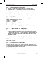
FIG. 5 - CONNECTIONS
Connect the wires in accordance with the diagram. The wires must
be connected as follows:
Term. 1: Neutral (N)
Term. 2: Live (L)
Term. 3-4: Output, max. 16 A
Term. X: Do not connect
RTF-TC
/ RTU-TC English
Term. 5-6: External floor sensor (RTF-TC Thermostats only)
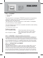
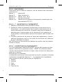
FIG. 6 + 7 - MOUNTING THE THERMOSTAT
1. Mount the thermostat in the wall socket.
2. Fit the frame and carefully press the cover onto the thermostat
- starting with the upper part of the cover, then the lower part of
the cover. Ensure that both the power slide button on the cover
and the power switch pin in the thermostat are down.
3. Click the cover into place by applying light, even pressure.
Warning! Do not apply pressure to the corners of the display
cover or to the display itself.
DO NOT open the thermostat by releasing the four fixing clips on
the back.
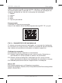
FIG. 8 - OPERATING THE THERMOSTAT
There is an ON/OFF switch on the left side of the thermostat: up is
ON - down is OFF.
The resistive touchscreen requires a soft tap with your fingertip to
register the touch.
Installer Wizzard:
The first time the thermostat is connected, push the power slide
button to On “I” The Installer Wizard on the touchscreen will guide
you through the set up of:
1. Region
2. Language
3. Date
4. Time
5. Floor Type
Programming
See user manual.
https://csd.stiebel-eltron.de/Montageanweisung/RTF-TC_en.pdf
RTF-TC / RTU-TC English

© 2018 OJ Electronics A/S 9© 2018 OJ Electronics A/S
To prevent loose wires in the fixed installation from coming into
contact with the terminal block for the floor sensor, they must be
restrained using cable ties.
It is strongly recommended that the cable and sensor are placed in
a non-conductive installation pipe embedded in the floor. The end
of the pipe must be sealed and the pipe placed as high as possible
in the concrete layer. The sensor cable must be led through a
separate conduit or segregated from power cables.
The floor sensor must be centred between loops of heating cable.
The sensor cable may be extended up to 100 m by means of a
separate two-core cable. Two vacant wires in a multi-core cable
used, for example, to supply current to the floor heating cable must
not be used. The switching peaks of such current supply lines may
create interference signals that prevent optimum thermostat func-
tion. If a shielded cable is used, the shield must not be connected
to earth (PE). The two-core cable must be placed in a separate
pipe or segregated from power cables in some other way.
Mounting of thermostat with built-in sensor
The room sensor is used for comfort temperature regulation in
rooms. The thermostat should be mounted on the wall approx.
1.5 m above the floor in such a way as to allow free air circulation
around it. Draughts and direct sunlight or other heat sources must
be avoided.
FIG. 4 - OPENING THE THERMOSTAT
1. Slide the power button down to O “0”.
2. Release the front cover ONLY by inserting a small screwdriver
into the slot at the centre of the bottom side of the front cover to
press and hold the catch securing the front cover.
3. Then carefully pull the front cover away, initially from the lower
part of the thermostat, then from the upper part of the thermo-
stat.
FIG. 5 - CONNECTIONS
Connect the wires in accordance with the diagram. The wires must
be connected as follows:
Term. 1: Neutral (N)
Term. 2: Live (L)
Term. 3-4: Output, max. 16 A
Term. X: Do not connect
Term. 5-6: External floor sensor (RTF-TC Thermostats only)
FIG. 6 + 7 - MOUNTING THE THERMOSTAT
1. Mount the thermostat in the wall socket.
2. Fit the frame and carefully press the cover onto the thermostat
- starting with the upper part of the cover, then the lower part of
the cover. Ensure that both the power slide button on the cover
and the power switch pin in the thermostat are down.
3. Click the cover into place by applying light, even pressure.
Warning! Do not apply pressure to the corners of the display
cover or to the display itself.
DO NOT open the thermostat by releasing the four fixing clips on
the back.
FIG. 8 - OPERATING THE THERMOSTAT
There is an ON/OFF switch on the left side of the thermostat: up is
ON - down is OFF.
The resistive touchscreen requires a soft tap with your fingertip to
register the touch.
Installer Wizzard:
The first time the thermostat is connected, push the power slide
button to On “I” The Installer Wizard on the touchscreen will guide
you through the set up of:
1. Region
2. Language
3. Date
4. Time
5. Floor Type
Programming
See user manual.
https://csd.stiebel-eltron.de/Montageanweisung/RTF-TC_en.pdf
RTF-TC / RTU-TC English

10 © 2018 OJ Electronics A/S © 2018 OJ Electronics A/S
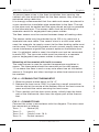
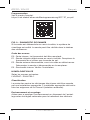
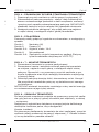
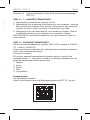
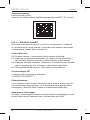
FIG. 9 - TROUBLESHOOTING
If the sensor is disconnected or short-circuited, the heating system
is switched o. The sensor can be checked against the resistance
table.
Error codes
E0: Internal fault. The thermostat must be replaced.
E1: Built-in sensor defective or short-circuited. Replace the ther-
mostat, or use the floor sensor only.
E2: External sensor disconnected, defective or short-circuited.
Reconnect the sensor if disconnected, or replace the sensor.
E5: Internal overheating. Inspect the installation.
CE marking
According to the following standard:
LVD/EMC: EN 60730-1
Classification
Protection from electric shock must be assured by appropriate
installation. Appropriate installation must meet the requirements of
Class II (enhanced insulation).
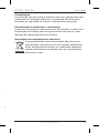
Environment and recycling
Please help us to protect the environment by disposing of the
packaging in accordance with national regulations for waste
processing.
Recycling of obsolete appliances
Appliances with this label must not be disposed of with
general household waste. They must be collected
separately and disposed of in compliance with local
regulations.
RTF-TC
/ RTU-TC English RTF-TC / RTU-TC English

© 2018 OJ Electronics A/S 11© 2018 OJ Electronics A/S
FIG. 9 - TROUBLESHOOTING
If the sensor is disconnected or short-circuited, the heating system
is switched o. The sensor can be checked against the resistance
table.
Error codes
E0: Internal fault. The thermostat must be replaced.
E1: Built-in sensor defective or short-circuited. Replace the ther-
mostat, or use the floor sensor only.
E2: External sensor disconnected, defective or short-circuited.
Reconnect the sensor if disconnected, or replace the sensor.
E5: Internal overheating. Inspect the installation.
CE marking
According to the following standard:
LVD/EMC: EN 60730-1
Classification
Protection from electric shock must be assured by appropriate
installation. Appropriate installation must meet the requirements of
Class II (enhanced insulation).
Environment and recycling
Please help us to protect the environment by disposing of the
packaging in accordance with national regulations for waste
processing.
Recycling of obsolete appliances
Appliances with this label must not be disposed of with
general household waste. They must be collected
separately and disposed of in compliance with local
regulations.
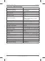
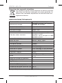
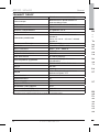
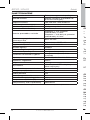
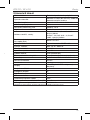
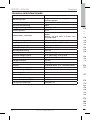
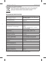
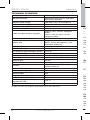
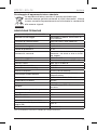
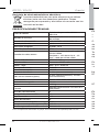
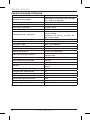
TECHNICAL SPECIFICATIONS
Purpose of control Electrical underfloor heating
Method of mounting.
Wall mounting in a socket or
mounting box
Supply voltage 100-240 VAC ±10% 50/60 Hz
Max. pre-fuse 16 A
Built-in interupter 2-pole, 16 A
Enclosure rating IP 21
Wire size, terminals
Current ≤ 13 A - 1.5 mm
2
, solid core
wire
Current > 13 A to 16 A - 2.5 mm
2
,
solid core wire
ELV limits realized SELV 24 VDC
Output relay Make contact - SPST - NO
Output, load Max. 16 A / 3600 W
Control principle PWM/PI
Standby consumption ≤0.5 W
Battery backup 5 years (storage)
Battery life, typical 5 years (storage) 10 years (powered)
Dimensions MxD5: H/84, W/84, D/40 mm
Build-in depth 22mm
Weight ≤200 g
Display 176x220 pixels TFT - resistive touch
Control pollution degree 2
Overvoltage category III
Type of action 1.B
Software class A
Rated impulse voltage 4kV
Ball pressure temperature (TB) 125°C
EU registered design DM/082270
Note: At very low ambient temperatues the display may respond slowly.
RTF-TC / RTU-TC English
Page is loading ...
Page is loading ...
Page is loading ...
Page is loading ...
Page is loading ...
Page is loading ...
Page is loading ...
Page is loading ...
Page is loading ...
Page is loading ...
Page is loading ...
Page is loading ...
Page is loading ...
Page is loading ...
Page is loading ...
Page is loading ...
Page is loading ...
Page is loading ...
Page is loading ...
Page is loading ...
Page is loading ...
Page is loading ...
Page is loading ...
Page is loading ...
Page is loading ...
Page is loading ...
Page is loading ...
Page is loading ...
Page is loading ...
Page is loading ...
Page is loading ...
Page is loading ...
Page is loading ...
Page is loading ...
Page is loading ...
Page is loading ...
Page is loading ...
Page is loading ...
Page is loading ...
Page is loading ...
Page is loading ...
Page is loading ...
Page is loading ...
Page is loading ...
Page is loading ...
Page is loading ...
Page is loading ...
Page is loading ...
Page is loading ...
Page is loading ...
Page is loading ...
Page is loading ...
Page is loading ...
Page is loading ...
Page is loading ...
Page is loading ...
Page is loading ...

© 2018 OJ Electronics A/S © 2018 OJ Electronics A/S
RTF-TC / RTU-TC
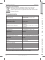
ESPECIFICAÇÕES TÉCNICAS
Finalidade do controlo Aquecimento elétrico de piso
Método de montagem.
Montagem na parede numa tomada
ou caixa de montagem
Tensão de alimentação 100-240 VAC ±10% 50/60 Hz
Pré-fusível máx. 16 A
Interruptor embutido 2 polos, 16 A
Grau de proteção IP 21
Tamanho de fios, terminais
Corrente ≤ 13 A - 1,5 mm², fio de
núcleo sólido
Corrente > 13 A a 16 - 2,5 mm², fio
de núcleo sólido
Limites de VLE realizados SELV 24 VCC
Relé de saída Contacto - SPST - NO
Carga de saída Máx. 16 A/3600 W
Princípio de controlo PWM/PI
Consumo em modo de espera ≤0,5 W
Bateria de reserva 5 anos (armazenada)
Vida útil da bateria, normal
5 anos (armazenada) 10 anos
(alimentada)
Dimensões MxD5: A/84, L/84, P/40 mm
Profundidade incorporada 22 mm
Peso ≤200 g
Monitor
TFT 176x220 píxeis - resistente ao
toque
Nível de controlo de poluição 2
Categoria de sobretensão III
Tipo de ação 1.B
Classe de software A
Tensão de impulso nominal 4kV
Temperatura de pressão esférica 125°C
Design registado na UE DM/082270
Nota: O monitor pode ficar lento em temperaturas ambiente muito baixas.

70
RTF-TC
RTU-TC
© 2017 OJ Electronics A/S
The trademark is registered and belongs to OJ Electronics A/S · © 2018 OJ Electronics A/S
67708C 03/18 (JRK)
Deutschland
STIEBEL ELTRON GmbH & Co. KG
Dr.-Stiebel-Straße 33 | 37603 Holzminden
Tel. 05531 702-0 | Fax 05531 702-480
info@stiebel-eltron.de
www.stiebel-eltron.de
Verkauf
Tel. 05531 702-110 | Fax 05531 702-95108 | info-center@stiebel-eltron.de
Kundendienst
Tel. 05531 702-111 | Fax 05531 702-95890 | kundendienst@stiebel-eltron.de
Ersatzteilverkauf
Tel. 05531 702-120 | Fax 05531 702-95335 | ersatzteile@stiebel-eltron.de
Australia
STIEBEL ELTRON Australia Pty. Ltd.
6 Prohasky Street
Port Melbourne VIC 3207
Tel. 03 9645-1833 | Fax 03 9645-4366
info@stiebel.com.au
www.stiebel.com.au
Austria
STIEBEL ELTRON Ges.m.b.H.
Gewerbegebiet Neubau-Nord
Margaritenstraße 4 A | 4063 Hörsching
Tel. 07221 74600-0 | Fax 07221 74600-42
info@stiebel-eltron.at
www.stiebel-eltron.at
Belgium
STIEBEL ELTRON bvba/sprl
't Hofveld 6 - D1 | 1702 Groot-Bijgaarden
Tel. 02 42322-22 | Fax 02 42322-12
info@stiebel-eltron.be
www.stiebel-eltron.be
Czech Republic
STIEBEL ELTRON spol. s r.o.
K Hájům 946 | 155 00 Praha 5 - Stodůlky
Tel. 251116-111 | Fax 235512-122
info@stiebel-eltron.cz
www.stiebel-eltron.cz
Finland
STIEBEL ELTRON OY
Kapinakuja 1 | 04600 Mäntsälä
Tel. 020 720-9988
info@stiebel-eltron.fi
www.stiebel-eltron.fi
France
STIEBEL ELTRON SAS
7-9, rue des Selliers
B.P 85107 | 57073 Metz-Cédex 3
Tel. 0387 7438-88 | Fax 0387 7468-26
info@stiebel-eltron.fr
www.stiebel-eltron.fr
Netherlands
STIEBEL ELTRON Nederland B.V.
Daviottenweg 36
5222 BH 's-Hertogenbosch
Tel. 073 623-0000 | Fax 073 623-1141
info@stiebel-eltron.nl
www.stiebel-eltron.nl
Poland
STIEBEL ELTRON Polska Sp. z O.O.
ul. Działkowa 2 | 02-234 Warszawa
Tel. 022 60920-30 | Fax 022 60920-29
biuro@stiebel-eltron.pl
www.stiebel-eltron.pl
United Kingdom and Ireland
STIEBEL ELTRON UK Ltd.
Unit 12 Stadium Court
Stadium Road | CH62 3RP Bromborough
Tel. 0151 346-2300 | Fax 0151 334-2913
info@stiebel-eltron.co.uk
www.stiebel-eltron.co.uk
4<AMHCMO=cidcgd>
Ir r tum un d tec h ni s che Änd e run g e n vo rbe h al te n! | S ub je ct to er r or s an d tec h ni ca l ch a nge s ! | So u s rés e rv e
d ‘e r r e u r s e t d e m o d i f i c a t i o n s t e ch n i q u e s ! | O n d e r v o o r b e h o u d v a n v e r g i s s i n g e n e n t e c h n i s c h e w i j z i g i n g e n ! |
Salvo error o modificación técnica! | Excepto erro ou alteração técnica | Zastrzeżone zmiany techniczne i
ew ent ual n e bł ę dy | Om yl y a te c hni ck é zm ě ny js ou vy h ra z en y! | A mus zak i vál toz ta tás ok és té ved ése k jo g át
fenntartjuk! | Отсутс твие ошибок не гарант ируетс я. Возм ожны тех ническ ие изм енения. | Ch y by a
technické zmeny sú vyhradené! Stand 9147
A 328326-40440-9331
99_328326-40440-9331_RTF-TC_Installation.indd 1 31.01.2018 13:49:04
-
 1
1
-
 2
2
-
 3
3
-
 4
4
-
 5
5
-
 6
6
-
 7
7
-
 8
8
-
 9
9
-
 10
10
-
 11
11
-
 12
12
-
 13
13
-
 14
14
-
 15
15
-
 16
16
-
 17
17
-
 18
18
-
 19
19
-
 20
20
-
 21
21
-
 22
22
-
 23
23
-
 24
24
-
 25
25
-
 26
26
-
 27
27
-
 28
28
-
 29
29
-
 30
30
-
 31
31
-
 32
32
-
 33
33
-
 34
34
-
 35
35
-
 36
36
-
 37
37
-
 38
38
-
 39
39
-
 40
40
-
 41
41
-
 42
42
-
 43
43
-
 44
44
-
 45
45
-
 46
46
-
 47
47
-
 48
48
-
 49
49
-
 50
50
-
 51
51
-
 52
52
-
 53
53
-
 54
54
-
 55
55
-
 56
56
-
 57
57
-
 58
58
-
 59
59
-
 60
60
-
 61
61
-
 62
62
-
 63
63
-
 64
64
-
 65
65
-
 66
66
-
 67
67
-
 68
68
-
 69
69
-
 70
70


STIEBEL ELTRON RTF-TC | RTU-TC Operation Instruction
- Type
- Operation Instruction
Ask a question and I''ll find the answer in the document
Finding information in a document is now easier with AI
in other languages
- italiano: STIEBEL ELTRON RTF-TC | RTU-TC
- français: STIEBEL ELTRON RTF-TC | RTU-TC
- español: STIEBEL ELTRON RTF-TC | RTU-TC
- Deutsch: STIEBEL ELTRON RTF-TC | RTU-TC
- Nederlands: STIEBEL ELTRON RTF-TC | RTU-TC
- português: STIEBEL ELTRON RTF-TC | RTU-TC
- polski: STIEBEL ELTRON RTF-TC | RTU-TC
- čeština: STIEBEL ELTRON RTF-TC | RTU-TC
- svenska: STIEBEL ELTRON RTF-TC | RTU-TC
- suomi: STIEBEL ELTRON RTF-TC | RTU-TC
Related papers
-
STIEBEL ELTRON RTF-TC | RTU-TC Operation Instruction
-
-
-
-
-
Other documents
-
OJ Electronics OCD5 Operating instructions
-
Danfoss FH-WC connection box Installation guide
-
-
-
AEG FRTD 902 User manual
-
 Aircalo PB 172 Installation and Maintenance Manual
-
 Watts Industries WFHTRF-HC User manual
-
OJ Electronics MCD5-UA Operating instructions
-
OJ Electronics MSD4-1999-UA Operating instructions
-
OJ Electronics OCC4 Operating instructions

