Page is loading ...

© MuxLab Inc. 2007 rev b
Specifications
Environment: Private and public broadband CATV, VHF and FM networks.
Devices: Terrestrial CATV, local channel amplified antennas, DVD players,
RF modulators, splitters, cable modems and other broadband video
equipment.
Transmission: Transparent to the user
3dB bandwidth: 5 MHz to 900 MHz.
Video Channels Sup-
ported:
CATV 2-142, VHF channels 2-13, FM broadcast band.
Insertion Loss Per Pair: <9 dB: 5 – 10 MHz <3 dB: 10 – 900 MHz
Return Loss: >10 dB: 15 – 370 MHz >7 dB: 370 – 770 MHz
>10 dB: 770 – 900 MHz
Common Mode Rejec-
tion (CMMR):
-20dB or higher at 5 MHz to 900 MHz.
Cable – UTP: 24-AWG or lower solid copper twisted pair.
Impedance: 100-120-ohms
Cable – Coax: Impedance: 75-ohms at 1MHz (RG6)
Connector – Input: “F” connector – male
Connector - Output: RJ45 – female
RJ45 Pin Configura-
tion:
RJ45 Pins 7&8.
Maximum distance: Up to 100m (330ft) via Cat 5 UTP depending on channel fre-
quency and input power. Maximum 100m at CATV Channel 2.
May require tilt amplifiers at higher frequencies.
Temperature: Operating: 0° to 40°C. Storage: -10° to 70°C.
Enclosure: ABS.
Humidity: Maximum 95% (non-condensing)
Dimensions: 2.5” x 1” diameter (6.35 x 2.54 cm diameter)
Weight 1.05 oz (30 gms)
Regulatory Approval: FCC, CE
Warranty: Lifetime
Order Information 500302 CATV Balun II
Tel.: (514) 905-0588, Fax: (514) 905-0589
Toll Free (North America): (877) 689-5228
E-mail: [email protected]
URL: www.muxlab.com
94-000605-B SE-000582-B
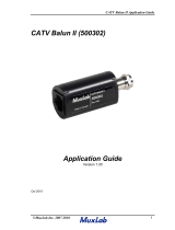
VideoEase CATV Balun II
(500302)
Quick Installation Guide
Overview
The CATV Balun II allows traditional 75-ohm coaxial cable to be replaced by a single
(1) unshielded twisted pair (UTP) of wires in the CATV, VHF and FM environments.
Used in pairs, the CATV Balun II allows terrestrial broadband video and Internet equip-
ment to be integrated into a structured cabling system thereby facilitating moves, adds
and changes via any convenient modular wall outlet. Typically, the CATV Balun II is
installed on the connection between the RF head end and the set-top tuner or cable mo-
dem at the receiver end. Applications include; private RF networks, guestroom TV and
Internet services, apartments and condominiums. The CATV Balun II is designed for
point-to-point connections only.
Installation
In order to install the CATV Balun II, perform the following steps:
1. Verify that the maximum distance between the two (2) CATV baluns is within
MuxLab specifications. Please refer to the specification table in this installation
guide or contact MuxLab Technical Support.
2. Caution: Do not attempt to open the housing. There are no user-serviceable
parts inside the CATV Balun II. Opening the unit will void your warranty.
3. Turn off power and disconnect the CATV video equipment by following the manu-
facturer’s instructions.
4. Make certain that modular outlets and cross connects to which you will connect
the CATV Balun II are configured properly and labeled appropriately to identify
the circuit.
5. Caution: Do not connect the CATV Balun II to a telecommunication outlet wired
to unrelated equipment. Making such a connection may damage the equipment
and/or the balun. Please ensure that all wiring is “straight-through” twisted pair.
6. Verify that the desired twisted pairs are not being used for other LAN or telephony
equipment.
7. The CATV Balun II operates in pairs.

© MuxLab Inc. 2007 rev b
8. Connect one CATV Balun II to the RF output at the head-end.
9. Caution: Do not mount the balun over equipment ventilation openings.
Covering the openings may cause the equipment to overheat.
10. Connect a line cord from the RJ45 modular jack of the CATV Balun II to the hori-
zontal wiring of the building.
11. At the receiver end, connect a CATV Balun II to the set -top tuner or cable mo-
dem.
12. Connect a line cord from the RJ45 connector of the CATV Balun II to the appro-
priate modular video wall outlet.
13. Power on the video equipment. See typical application below.
Troubleshooting
The following table describes some of the symptoms, probable causes and possible solu-
tions in respect to the installation of the CATV Balun II. If you still cannot diagnose
the problem, please call MuxLab Customer Technical Support at 877-689-5228 (toll-
free in North America) or (+1) 514-905-0588 (International).
Symptom Probable Causes Possible Solutions
No video No continuity in video link
Check cable continuity between baluns.
No video No power Check power supplies.
No video Improper connection
Swapped pairs
Check that baluns are connected to cor-
rect video inputs and outputs.
Snowy picture Insufficient signal strength Increase signal power at head-end using a
“tilt” amplifier. Verify cable grade. Use
higher grade cable if necessary.
Over bright
image
Signal strength too high Attenuate signal by reducing amplifier
gain or by inserting a signal attenuator in
the link.
Application Tips
In a point-to-point scenario for CATV (superband and hyperband), VHF and FM, cable lengths of
up to 45 meters may be achieved without amplification if the nominal input is about 15dBm. In
some applications, a tilt amplifier may be required since the UTP losses are higher than coax at
the higher frequencies. Linear gain compensation of up to 20-25dB at 750MHz is usually ade-
quate. Conversely, if amplification is used to compensate for losses at higher frequencies and long
distances, it may be necessary to attenuate the lower frequency, shorter distance signals to avoid
over-driving the TV monitors. The CATV Balun II may be used in conjunction with tilt/gain am-
plifiers, CATV splitters and splitters with built-in amplifiers. The following are some helpful
guidelines when planning your cabling:
1. Try for 10dBmv of signal level at each television channel. Use a little more for big screen
TVs. Measure the signal level at the high and low end of the spectrum to determine whether
a tilt amplifier is needed.
2. When laying out your system, there will be approximately 5dB of signal loss per 100' of
RG6 -coaxial cable.
3. Please ensure all splitters and amplifiers are broadband. For UTP installations, splitters should
have 5 MHz to 900 MHz bandwidth with a bi-directional filter at 5 to 50 MHz.
4. Check and make sure that all televisions are set up for the proper frequency spectrum (i.e.
UHF or cable).
5. If extra channels are available, allow 1 to 2 channels spacing between “modulated” and "ac-
tive" channels.
6. Always compensate for insertion loss with a good amplifier. There will always be a drop in
signal strength when combining a modulator to an existing system due to insertion loss from
the combiner.
7. When combining an existing signal with a modulated signal, make sure to have equal signal
strength at the point of the combiner so one signal does not degrade the other.
8. When possible, use the lowest frequencies available for the modulated channels. Lower fre-
quency channels have lower signal loss on the cable runs.
9. When in doubt, run the signal a little high to the television and use an attenuator to lower the
signal strength going into the TV. Attenuators may be combined (i.e. two -3dB attenuators
will = -6dB).
10. Combine the modulator into the video distribution system as far "up-stream" as possible.
11. If the system needs to be amplified, use the amplifier as far "up -stream" as possible. For
example, place one amplifier at the head end and one tilt amplifier in each wiring closet
where the baluns are located.
/