Bradford White EFC-5500-4-S-10 User manual
- Category
- Space heaters
- Type
- User manual

1
IF ASSTANCE IS REQUIRED OR ANY QUESTIONS RELATING TO THE
INSTALLATION OR PERFORMANCE OF THIS UNIT ARISE, CONTACT
TECHNICAL SERVICE TOLLFREE : 1-800-334-3393 .
HAVE THE INFORMATION LISTED BELOW BEFORE CALLING :
SERIAL NO. MODEL NO. INSTALLATION DATE
READ THE GENERAL SAFETY SECTION BEGINNING ON THE INSIDE COVER
AND THEN THIS ENTIRE MANUAL BEFORE INSTALLING OR OPERATING THIS
WATER HEATING UNIT. IF YOU DON’T FOLLOW THE SAFETY RULES, THE UNIT
WILL NOT OPERATE PROPERLY AND COULD CAUSE DEATH, SERIOUS BODILY
INJURY AND/OR PROPERTY DAMAGE. READ ALSO THE ENCLOSED
WARRANTY CARD. WARRANTY OF THIS WATER HEATING UNIT WILL DEPEND
ON PROPER INSTALLATION AND OPERATION. THE WARRANTY SHALL BE
VOID IF THE DESIGN HAS BEEN ALTERED IN ANY WAY WHATSOEVER. THE
MANUFACTURER OF THIS UNIT WILL NOT BE LIABLE FOR ANY DAMAGES
BECAUSE OF FAILURE TO COMPLY WITH THE INSTALLATION AND
OPERATING INSTRUCTIONS OUTLINED ON THE FOLLOWING PAGES.
THE INSTALLATION MUST CONFORM WITH THE INSTRUCTIONS IN THIS
MANUAL; ELECTRIC COMPANY RULES; AND THE LOCAL CODES, OR IN
THE ABSENCE OF LOCAL CODES, WITH THE LATEST EDITION OF THE
NATIONAL ELECTRICAL CODE. A COPY OF THE N.E.C IS AVAILABLE FROM
UNDERWRITERS LABORATORIES, 333 PFINGSTEN ROAD
NORTHBROOK, IL, 60062.
WARNING
ELECTRIC INSTANTANEOUS
TANKLESS WATER HEATER
“THREE PHASE THERMOSTATIC”
INSTALLATION GUIDE AND OWNERS MANUAL
MODEL(S) COVERED: EFT-18000-2-T-10
EFT-18000-6-T-10
EFT-24000-2-T-10
EFT-24000-6-T-10
EFT-28000-4-T-10
EFT-32000-6-T-10

GENERAL
This “Three Phase Thermostatic” water heating unit is specifically designed to take in
cold or pre-heated water and heat it to temperatures suitable for commercial washing,
sluicing or processing, up to a maximum temperature of 180° F (82° deg. C). To obtain
optimum performance and energy savings, this unit should be located as near as possible
to the point of use. This unit must only be installed in a vertical position with the inlet
and outlet at the bottom. The power is activated by individual electronic flow switches located
in each of the three heating modules. These will be damaged by excessive heat, do not solder
any pipes that are in contact with the heater. Also ensure pipes are clear of installation debris
before connecting the water heating unit, otherwise the flow switches could jam in the
“on” position. This unit must be connected to its own individual electric circuit protected by
a suitably rated three pole breaker. The maximum voltage which can be applied across any
heating module is 277 volts. It is recommended that a Pressure Relief Valve be installed
as close as possible to the heater outlet of the unit ( per code).
WARNING
Improper installation, adjustment, alteration, service or maintenance can cause DEATH,
SERIOUS BODILY INJURY OR PROPERTY DAMAGE. Refer to this manual for
assistance or consult the local electric utility for further information.
This unit is supplied with compression rings and nuts suitable for direct coupling to
standard 1/2 “ ( 5/8 “ outside diameter ) copper or plastic piping. There is no need for
additional screwed fittings and under no circumstances shall a blow torch be used on pipe
connected to the unit (serious damage to the electronic flow switch will result).
WARNING
Failure to ground the system may result in death or serious injury.
2
ELECTRICAL SHOCK HAZARD! BEFORE REMOVING THE COVER OR SERVICING THE
WATER HEATER, MAKE SURE THE ELECTRICAL SUPPLY TO THE WATER HEATING
UNIT IS TURNED “OFF”. FAILURE TO DO SO CAN RESULT IN DEATH, SERIOUS
BODILY INJURY, OR PROPERTY DAMAGE.

MOUNTING THE UNIT
1) This unit should be mounted as close to the point of use as possible.
2) This unit must only be mounted in the vertical position with the water fittings located at the
bottom of the unit. Mounting other than in the vertical position WILL cause element burn out.
3) The cold water inlet is on the right hand side and the hot water outlet is on the left hand side.
Under NO circumstances can these be reversed.
4) Leave a minimum of 8” above the unit for easy replacement of the elements.
5) This unit should be fixed to the wall using screws in the four mounting holes at each corner
of the backplate.
6) The unit should be installed in the plumbing system in such a way that there is no tendency
for the unit to be starved of water: for example: by an excessive draw-off of cold water just
before the unit. Also do not fit an unrestricted hot water draw-off point below the heater as
this will tend to empty the heater by siphoning.
NOTE
ALL MOUNTING AND PLUMBING MUST BE COMPLETE BEFORE YOU PROCEED
WITH ELECTRICAL HOOK-UP.
TEST THE INSTALLATION FOR LEAKS BEFORE CONNECTING THE
ELECTRICAL SUPPLY.
3
7) It is possible that drawing off water at comparatively high rates of flow elsewhere in the
building at the same time that the heater is working, could cause premature element failure.
Care should be taken not to starve the unit of water. To prevent this from happening, open
fully the main valve of the incoming water supply to the building and throttle back the
control valves to the other water outlets.

1) This unit is supplied with compression fittings, USE THESE; DO NOT USE TAPERED
THREADED PIPE FITTINGS AND DO NOT SOLDER PIPE TO THE INLET OR OUTLET.
2) Ensure that the pipes are correctly aligned with the inlet and outlet bosses in
order to avoid excessive stress on the heater body molding of the unit.
NOTE: When soldering pipe joints remove unit from the wall. Serious damage can occur
if any soldering is done while pipes are connected to the unit.
Run water through the supply pipe to remove all debris from the pipe before connecting to
the unit. Failure to do so could cause damage to the flow switch.
3) Install isolating valves (full flow ball valve type) on both inlet and outlet pipes. This allows
the unit to be isolated for maintenance purposes.
4) When all plumbing is complete, inspect the system for water leaks at all plumbing
connections. If a water leak is present take corrective action. If a water leak is at a
compression fitting, slowly tighten the compression nut until the water leak stops. Fully open
both inlet and outlet ball valves. Run all hot water outlets fed by this water heating unit one
at a time until the water flow is continuous and free from ”gulping” and all visible air
pockets.
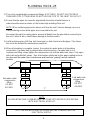
PLUMBING HOOK-UP
NOTE
ALL MOUNTING AND PLUMBING MUST BE COMPLETE BEFORE PROCEEDING
WITH ELECTRICAL HOOK-UP.
TEST THE INSTALLATION FOR LEAKS BEFORE CONNECTING THE
ELECTRICAL SUPPLY.
7 “
Hot water outlet
compression
fitting
DO NOT
SOLDER
Cold water inlet
compression
fitting
DO NOT
SOLDER
4

ELECTRICAL HOOK-UP
WARNING
WATER HEATING UNITS EQUIPPED FOR ONE VOLTAGE ONLY: CHECK THE RATING
PLATE ON THE FRONT OF THE UNIT. DO NOT USE THIS WATER HEATER WITH ANY
VOLTAGE OTHER THAN THE ONE SHOWN ON THE MODEL RATING PLATE. FAILURE TO
DO SO CAN RESULT IN DEATH, SERIOUS BODILY INJURY, OR PROPERTY DAMAGE. IF
YOU HAVE ANY QUESTIONS OR DOUBTS CONSULT YOUR ELECTRIC COMPANY.
This unit must have its own independent circuit using five wires; three live,one neutral and
one ground of the appropriate rating protected by the correctly rated three pole breaker
IMPORTANT
BEFORE SWITCHING “ON” THE POWER AT THE MAIN CIRCUIT BREAKER PANEL MAKE
SURE THAT THE HOT WATER CIRCUIT IS FREE OF AIR POCKETS OR PREMATURE
FAILURE OF THE ELEMENT WILL OCCUR. TO DO THIS OPEN ALL HOT WATER OUTLETS
ONE AT A TIME FOR A MINUTE OR TWO UNTIL THE WATER FLOW IS CONTINUOUS AND
FREE FROM “GULPING” AND FROM VISIBLE AIR POCKETS.
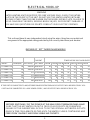
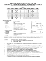
RATINGS OF “ EFT” THREE PHASE MODELS
5
CURRENT TEMPERATURE RISE IN DEGREES
MODEL RATING(KW) VOLTAGE(V) PER PHASE 1.5GPM 2.0GPM 2.5GPM 3.0GPM 3.5GPM 4.0GPM 5.0GPM
*EFT-18000-T-10 18 208/120 50A/PHASE 82 61 49 41 35 32 25
*EFT-24000-T-10 24 208/120 67A/PHASE 0 82 65 54 47 43 34
*EFT-18000-T-10 18 277 21.7A/PHASE 82 61 49 41 35 32 25
*EFT-24000-T-10 24 277 28.9A/PHASE 0 82 65 54 47 43 34
*EFT-32000-T-10 32 277 38.5A/PHASE 0 0 87 73 62 58 45
*EFT-28000-T-10 28 240 40A/PHASE 128 90 72 65 55 47 38
IF THE UNIT IS CONNECTED TO 460/265 THREE PHASE SYSTEM THE ABOVE OUTPUTS WILL BE REDUCED BY 8.5%
* UNIT MAY BE CONNECTED TO A 208V POWER SUPPLY, ABOVE OUTPUTS WILL BE REDUCED BY 25%

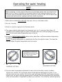
Operating the water heating
unit
IMPORTANT
Before switching “on” the power at the main circuit breaker panel make sure that the hot
water circuit is free of air pockets or premature failure of the heating element will occur.
To do this open all hot water faucets one at a time for a minute or two until the water flow
is continuous and free from “gulping” and from visible air pockets.
1) With inlet and outlet BALL VALVES fully open, turn on a hot water outlet.
2) Run for 1 minute.
3) Switch on electric supply at circuit breaker panel.
4) The power indicator light should now illuminate (see Fig. 1), pulsing at first. Allow 40
seconds for the indicator lights to remain illuminated, the unit is now operating at full power.
NOTE: At this point water temperature may not be hot.
5) Using the OUTLET BALL VALVE slowly reduce water flow until desired water temperature
is achieved at hot water outlet.
NOTE: The water temperature is regulated by the flow through the heater. The lower the
flow the higher the water temperature and vice versa.
MINIMUM SETTING
MAXIMUM SETTING
THE TEMPERATURE CONTROLLING
POTENTIOMETER IS A PRECISION
COMPONENT. ADJUST GENTLY AND
DO NOT TURN BEYOND THE MIN.
AND MAX. STOP POINTS
6) Turn the water temperature adjustment screw on the first module counter clockwise
1/8 of a turn, wait for 10-15 seconds and see if the indicator light begins to pulse. If the
indicator does not, turn another 1/8 of a turn, wait and again see if the lamp begins to pulse.
Repeat until the light is pulsing regularly which indicates that the temperature has stabilized
at the set temperature. Repeat with modules two and three. Check that the outlet temperature
6

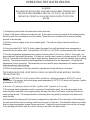
OPERATING THE WATER HEATER
WARNING
HOUSEHOLDS WITH SAMLL CHILDREN OR ELDERLY PERSONS MAY
REQUIRE WATER TEMPERATURES OF 125°F(52°C) OR LOWER TO
PREVENT ACCIDENTAL SCALDING FROM CONTACT WITH THE
WATER
1) Completely open both the inlet and outlet valves at the unit.
2) Open all hot water outlets serviced by this unit. If the outlet is a mixer type adjust to the hottest position.
Run flow until flow is continuous at all the outlets. When the flow is continuous at all serviced outlets,
proceed to the next step.
3) Switch on electric supply at the circuit breaker panel. The indicator light on the unit should now
illuminate.
4) Using the outlet BALL VALVE, slowly reduce the water flow until the desired water temperature is
achieved at the hot water outlet. This should be 120°f(49°c) to 140°f(60°c) without mixing with cold water.
5) Turn the temperature adjustment screw counter clockwise about 1/8 of a turn. After 10-15 seconds, the
power indicator light should be pulsing. If it does not, turn the screw counter-clockwise another 1/8 of a turn.
Wait 10-15 seconds for the indicator light to begin pulsing. Repeat process until the indicator light is pulsing
regularly. This indicates that the water temperature has stabilized at the set temperature. Check that the
temperature is what is required. The thermostat is now set and the water temperature will remain constant
when the indicator light is pulsing.
6) Check the performance of the flow switch by opening and closing the faucet a few times.
THE POWER INDICATOR LIGHT SHOULD ONLY ILLUMINATE WHEN WATER IS FLOWING
TROUGH THE UNIT.
NOTE: An EFT-9500-S-10 (9.5 kw) unit at 240v will deliver 1 gallon per minute at 65°F(18°C) rise in
temperature. For example, with an incoming water temperature of 55°F(13°C) the unit will produce 1 gallon
per minute at 120°F(49°C)
A flow rate of 1 gallon per minute will fill a 1 gallon “milk” container in 60 seconds.
7) For accurate water temperature control a mixer type faucet(single spout), the cold water supply to the
faucet should be restricted to give approximately the same flow rate of cold water to the faucet as the hot
water exiting the unit. The simplest method of achieving this is by partially closing the cold water valve
under the sink.
8) It is possible that drawing off cold water at comparatively high rates of flow elsewhere in the building at
the same time that the unit is working, could starve the unit of cold water. Care should be taken to avoid this
from occuring as premature element failure may result. Completely open the main valve on the cold supply
to the building and throttle back the control valvues to the other cold water outlets.

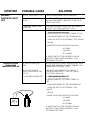
SYMPTOM POSSIBLE CAUSE SOLUTION
NO HEAT -
INDICATOR LIGHT
OFF
A) ELECTICAL SUPPLY OFF
B) NO OR LOW WATER
FLOW
C) WATER CONNECTION
REVERSED
D) ELEMENT BURNED OUT
TURN ON MAIN MAIN CIRCUIT BREAKER
MINIMUM WATER FLOW TO TURN ON UNIT IS 0.7
GALLON PER MINUTE. INCREASE FLOW TO AT
LEAST THIS LEVEL.
COLD WATER INLET-RIGHT SIDE. HOT WATER
OUTLET - LEFT SIDE. REFER TO FIG. 1
1) TURN MAIN BREAKER OFF
2) USING OHMETER TEST RESISTENCE OF THE
HEATING ELEMENT AT TWO TERMINATION
RODS ON THE TOP OF ELEMENT. SEE FIGURE
BELOW.
3) OHMETER SHOULD READAS FOLLOWS:
- 6-7 OHMS
- 7-8 OHMS
- 10-11 OHMS
IF RESISTENCE OF THE ELEMENT IS MUCH
GREATER THAN THESE READINGS - CALL
TECHNICAL SUPPORT.
NO HAET OR LOW
TEMERATURE
INDICATOR LIGHT ON
A) WATER FLOW TOO
HIGH
REDUCE WATER FLOW BY USING OUTLET BALL
VALVE. SEE ”RATINGS OF UNITS” TABLE P- FOR
TEMPERATURE RISE @ 1 GPM.
B) 110 VOLT POWER
SUPPLY INSTEAD OF 240
VOLTS
UNIT MUST BE CONNECTED TO 240 VOLT
POWER POWER SUPPLY. SEE SECTION III -
ELECTRICAL HOOK-UP.
C) ELEMENT BURNED OUT 1) TURN MAIN BREAKER OFF
2) USING OHMETER TEST RESISTENCE OF
THE
HEATING ELEMENT AT TWO TERMINATION
RODS ON THE TOP OF ELEMENT. SEE
FIGURE
BELOW.
3) OHMETER SHOULD READAS FOLLOWS:
- 6-7 OHMS
- 7-8 OHMS
- 10-11 OHMS
IF RESISTENCE OF THE ELEMENT IS MUCH
GREATER THAN THESE READINGS - CALL
TECHNICAL SUPPORT.


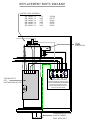
N L1 L2 L3
For supply connections use 8 AWG or
larger wires suitable for at least 75 c (167F)
THIS APPLIANCE MUST BE GROUNDED
This heater is only suitable for 4 wire
3 phase connection with a maximum of
277 volts across each element.
REPLACEMENT PARTS DIAGRAM
THERMOSTATIC
PCB
PART# EX100/VOLTAGE
HEATER CORE ASSEMBLY
FOR
TRIAC
PART# EX18
8
EFT-18000-T-10, 277V EX1280
EFT-18000-T-10 208V EX770
EFT-24000-T-10, 277V EX960
EFT-24000-T-10 208V EX560
EFT-32000-T-10 277V EX720
EFT-28000-T-10 240V EX630
COMPRESSION NUT AND
PLASTIC FARREL
PART # EX16, EX17
-
 1
1
-
 2
2
-
 3
3
-
 4
4
-
 5
5
-
 6
6
-
 7
7
-
 8
8
-
 9
9
-
 10
10


Bradford White EFC-5500-4-S-10 User manual
- Category
- Space heaters
- Type
- User manual
Ask a question and I''ll find the answer in the document
Finding information in a document is now easier with AI
Related papers
Other documents
-
EemaX EX180T3 Installation guide
-
-
-
Chief EFT-1 User manual
-
 Air Delights E-90 Installation and Operation Instructions
-
-
Cleveland Range CET-8 User manual
-
APC InRow Specification
-
HTP EFT-399PU Installation guide
-
EemaX SP2412 Installation guide
