Page is loading ...

• Read this Instruction Manual before using the product.
• Especially, read the safety notes carefully.
• Keep this Instruction Manual in a safe and convenient place for future reference.
SMALL SIZE FLOW SENSOR
RAPIFLOW® FSM3 Series
・LCD display type
・Bar display type
・IO-Link type
SM-662466-A/6
SM-358642
INSTRUCTION MANUAL
取扱説明書

SM-662466-A/6 PREFACE
i 2022-12-12
PREFACE
Thank you for purchasing CKD's "RAPIFLOW® FSM3 Series" compact size flow rate sensor.
This Instruction Manual contains basic items such as installation and usage instructions in order to
ensure optimal performance of the product. Please read this Instruction Manual thoroughly and use the
product properly.
Keep this Instruction Manual in a safe place and be careful not to lose it.
Product specifications and appearances presented in this Instruction Manual are subject to change
without notice.
• The product is intended for users who have basic knowledge about materials, piping, electricity, and
mechanisms of pneumatic components. CKD shall not be responsible for accidents caused by
persons who selected or used the product without knowledge or sufficient training.
• Since there are a wide variety of customer applications, it is impossible for CKD to be aware of all of
them. Depending on the application or usage, the product may not be able to exercise its full
performance or an accident may occur due to fluid, piping, or other conditions. It is the responsibility
of the customer to check the product specifications and decide how the product shall be used in
accordance with the application and usage.

SM-662466-A/6 SAFETY INFORMATION
ii 2022-12-12
SAFETY INFORMATION
When designing and manufacturing a device using this product, the customer is responsible to
manufacture a safe device. To achieve this, please verify the safety of electric control system is secured,
which controls the mechanical mechanism of the device and, pneumatic pressure control circuit or water
control circuit.
To ensure the safety of device design and control, observe organization standards, relevant laws and
regulations including the followings.
ISO 4414, JIS B 8370 and JFPS 2008 (the latest edition of each standard)
High Pressure Gas Safety Law, Occupational Safety and Health Law, and other safety regulations,
organization standards and regulations.
In order to use our products safely, it is important to select, use, handle, and maintain the products
properly.
Observe the warnings and precautions described in this Instruction Manual to ensure device safety.
Although various safety measures have been adopted in the product, customer's improper handling may
lead to an accident. To avoid this,
thoroughly read and understand this Instruction Manual before using the product.
To explicitly indicate the severity and likelihood of a potential harm or damage, precautions are classified
into three categories: "DANGER", "WARNING", and "CAUTION".
DANGER
Indicates an imminent hazard. Improper handling will cause death or serious
injury to people.
WARNING
Indicates a potential hazard. Improper handling may cause death or serious
injury to people.
CAUTION
Indicates a potential hazard. Improper handling may cause injury to people or
damage to property.
Note that some items described as "CAUTION" may lead to serious results depending on the situation.
Since each item provides important information, it must be observed.
Other general precautions and tips on using the product are indicated by the following icon.
Indicates general precautions and tips on using the product.

SM-662466-A/6 SAFETY INFORMATION
iii 2022-12-12
Precautions on Product Use
WARNING
This product must be handled only by those who have enough knowledge and experience.
This product was designed and manufactured as a general industrial machinery equipment and
parts.
This product must be used within its stated specifications.
Do not use out of the specifications unique to this product. In addition, never modify or additionally
machine this product.
This product is intended for use in general industrial machinery equipment or parts. It is not
intended for use in outdoors or for use under the following conditions or environments.
(Note that this product can be used when CKD is consulted prior to its usage and the customer
consents to CKD product specifications. However, even in that case, the customer should provide
safety measures to avoid danger to prevent danger in the event of failures.)
• Devices and usage that directly contact nuclear power, railways, aviation, ships, vehicles,
medical machines, beverages and foods.
• Use for applications requiring safety, including amusement, emergency cutoff circuits, press
machines, brake circuits, and items used for safety measures.
• Use for applications where life or assets could be significantly affected, and special safety
measures are required.
Do not handle this product, and remove piping / devices before confirming the safety.
• Conduct inspections and maintenance of machines and devices only after confirming the safety
of all systems related to this product. Also, turn the power OFF of supply air, supply water, and
applicable facilities that are energy sources. Make sure to exhaust compressed air inside the
system and be cautious of water and electricity leakages.
• As it is possible that there are high temperature parts and charged parts even after operation is
stopped, be cautious when handling this product and removing piping / devices.
• Before starting / restarting machines and devices that a pneumatic pressure device is used,
make sure to confirm the system safety is secured with pop-out prevention measures, etc.
Always adopt a fail safe mechanism when this product is used under a condition that a failure
leads to significant accidents.
CAUTION
Withstand pressure differs depending on each series.
Make sure to select the right product.
Be cautious of the followings when using with dynamic pressure near the maximum working
pressure.
With each series, the sensor can handle an overflow double the measures range. If dynamic
pressure is applied near the maximum working pressure (when a pressure difference exceeding
the max. working pressure is applied between primary and secondary sides), the sensor may
operate abnormally. If dynamic pressure is applied, such as when a work piece is filled for leakage
inspection, provide a bypass circuit or restrictor so that dynamic pressure is not applied to the
sensor.
The needle valve cannot be used as the stop valve that leakage is required to be zero.
The specifications of this product allows leakage to some extent.
The flow path is not completely free of dust generation.
A final clean filter should be used in circuits where dust generation could be a problem.
Use in a normal flow that does not include irregular fluctuations.
Measuring the pulsating flow rate may cause errors in the measured flow rate. Restrict the flow
rate with the fixed orifice and needle valve, etc., and use it in a laminar flow state.

SM-662466-A/6 SAFETY INFORMATION
iv 2022-12-12
CAUTION
The flow rate is fluctuating, the measured flow rate value will also fluctuate.
If the actual flow rate is fluctuating, the measured flow rate value will also fluctuate.
Either increase the FSM3 display cycle or response time, or average the analog output on the
device. In particular, note that control valves such as solenoid valves can be easily generated
when used near a circuit or pump that opens and closes quickly and frequently.
Be cautious of the followings when using for suction verification, etc.
[1] Mount an air filter upstream from suction in compliance with use conditions to prevent the entry
of foreign matter.
[2] Consider the atmospheric dew point and the product’s ambient temperature, and use the
product under conditions in which dew does not condense in pipes.
[3] When this product is used for vacuum applications such as air suction, do not bend the tube
near the push-in fitting.
If stress is applied to the tube near the push-in fitting, insert an insertion ring into the tube, and
connect the tube to the push-in fitting.
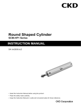
[4] When the confirmation sensor is switched from a pressure sensor (switch) to a flow rate sensor
(switch), sensor output (switch output) logic will be reversed. (Refer to the drawing below.)
Note that the PLC sequence program must be changed or revised.
If source pressure or vacuum source is not supplied when device power is turned on, “flow rate
0” = “sensor output (switch output) ON” status is set at the flow rate sensor (switch). Check that
this is not a problem with the PLC sequence program, etc.
[5] Select the flow rate range based on the operating vacuum pressure and suction nozzle
diameter.
Refer to “3.4 Flow rate theory calculation method”.
[6] Response speed may be delayed by the piping volume between the suction nozzle and this
product. In this case, take countermeasures to reduce piping capacity.
Precautions regarding used fluid
DANGER
Do not make a gas flow within the explosion limit.
Explosion accident may be generated.
When using a product with no oil-prohibited processing, do not flow oxygen gas.
It may cause fires. In addition, even if a product is treated with oil-prohibited processing, when a
gas except for oxygen gas is flowed once, do not use with oxygen gas again.
Pressure sensor (switch)
Flow rate sensor (switch)
Suction
verification
ON at setting value or more
ON at setting value or less
Atmospheric
pressure side
High vacuum
side
Flow rate
0 side
Flow rate
large side

SM-662466-A/6 SAFETY INFORMATION
v 2022-12-12
WARNING
Do not use this product as a transaction meter.
As it does not comply with Japanese Measurement Law and equivalent regulations of other
countries, do not use for commercial transactions. Use the product only as the sensor for industry
fields.
Appropriate fluid temperature is within 0 to 50°C.
Do not use in places where dew is generated by sudden temperature change even within the
temperature range.
Do not use fluids besides applicable fluids.
When fluids besides applicable fluids are used, the accuracy specification cannot be guaranteed.
Be cautious of purification level of fluid.
• Use dry gas which does not contain corrosive elements such as chlorine, sulfur or acids, and
which is clean and does not contain dust or oil mist.
• Depending on the fluid, retaining the fluid for a long time could adversely affect the performance.
Do not seal the fluid in the pipe for long periods of time.
• If this product is contaminated by foreign objects (dust and water drops inside piping, oil mist,
etc.), the accuracy and control performance may deteriorate and cause failure. If it may be
contaminated by foreign objects, attach a filter, air dryer and oil mist filter on the primary side
(upstream) of this product.
• When using compressed air, use clean air that complies with JIS B 8392-1:2012(ISO 8573-1:
2010) [Class 1:1:1 to 1:6:2].
• As drain (water, oxidized oil and foreign objects) may be contained in the compressed air from
the compressor, use this product by attaching a filter air dryer and oil mist filter (Micro-Alessa)
on the primary side (upstream).
The mesh (wire mesh) inside this product is to rectify the flow inside piping, and therefore, it
cannot be used to remove the flowed-in foreign objects.
<Recommended circuit>
Use this product after verifying the working pressure range and flow rate range.
• If used in maximum working pressure or more, minimum working pressure or less, and outside
of specified flow rate range, it may cause failures.
• If energized in a vacuum state of -0.09 MPa or less, the sensor’s heat dissipation will suffer,
leading to degradation of the sensor.
When using a valve on the primary side of this product, use a valve with oil-prohibited
specification and attach a filter.
This product may malfunction and result in failure due to grease on the valve, diffused oil, and
abrasion powder generated from the valve.
When using the valve with liquified gases such as carbon dioxide, always vaporize the gas.
Faults could result if the liquified gas enters this product.
Filter
Oil mist filter
(Micro-Alessa)
Regulator
Air dryer
Flow rate sensor
FSM3 Series
Pneumatic
pressure
source

SM-662466-A/6 SAFETY INFORMATION
vi 2022-12-12
Precautions regarding maintenance
CAUTION
Do not use solvents, alcohol, and cleaning detergents to clean this product.
The case is made of resin. The resin could absorb these chemicals. Wipe off dirt with a rag soaked
in a diluted neutral detergent solution and wrung out well.
Verify the flow rate accuracy periodically.
It is recommended to verify the flow rate accuracy periodically. Depending on the customer’s use
environment and condition, the accuracy may fluctuate from the first time. Also, if used for a long
time, the accuracy may fluctuate due to sensor chip deterioration.
Displayed flow rate on this product is a value of mass flow rate converted to volume flow rate.
It is displayed by converting measured mass flow rate to the volume flow rate at 20°C, 1
atmospheric pressure (101kPa), and relative humidity 65% RH (Gas types besides air uses
20°C, 1 atmospheric pressure (101kPa), and 0% RH).

SM-662466-A/6 CONTENTS
vii 2022-12-12
CONTENTS
PREFACE ........................................................................................................................... i
SAFETY INFORMATION .................................................................................................. ii
Precautions on Product Use .......................................................................................... iii
Precautions regarding used fluid ................................................................................... iv
Precautions regarding maintenance .............................................................................. vi
CONTENTS ..................................................................................................................... vii
1. PRODUCT OVERVIEW ............................................................................................. 1
1.1 Model No. display ............................................................................................... 1
1.1.1 LDC display type (FSM3-L Series) ................................................................ 1
1.1.2 Bar display (FSM3-B series) ......................................................................... 7
1.1.3 IO-Link (FSM3-C Series) ............................................................................. 13
1.1.4 Option .......................................................................................................... 17
1.2 Specifications .................................................................................................... 18
1.2.1 LCD display type ......................................................................................... 18
1.2.2 Bar display type ........................................................................................... 24
1.2.3 IO-Link type ................................................................................................. 30
1.3 Communication specification ............................................................................ 34
1.3.1 General ........................................................................................................ 34
1.3.2 On demand data .......................................................................................... 35
1.3.3 Parameter and commands .......................................................................... 37
1.3.4 Process data IN ........................................................................................... 39
1.3.5 Observation ................................................................................................. 39
1.3.6 Diagnosis ..................................................................................................... 40
1.4 Dimensions ....................................................................................................... 41
1.4.1 LDC display type ......................................................................................... 41
1.4.2 Bar display type ........................................................................................... 48
1.4.3 IO-Link type ................................................................................................. 53
1.4.4 Option .......................................................................................................... 57
1.4.5 Products weight ........................................................................................... 59
1.5 Option (ATEX Compliant) ................................................................................. 61
2. INSTALLATION ....................................................................................................... 62
2.1 Installation Environment ................................................................................... 62
2.2 Mounting Method .............................................................................................. 64
2.3 Piping Method ................................................................................................... 66
2.3.1 Cleaning the pipes ....................................................................................... 66
2.3.2 Sealant ......................................................................................................... 66
2.3.3 Piping direction ............................................................................................ 66
2.3.4 Tightening .................................................................................................... 67
2.3.5 EXA connection method .............................................................................. 68
2.4 Wiring method ................................................................................................... 69
2.4.1 LDC display (NPN output) ........................................................................... 71
2.4.2 LDC display type (PNP output) ................................................................... 72
2.4.3 Copying setting values ................................................................................ 73
2.4.4 Bar display type ........................................................................................... 73
2.4.5 Connection between Bar display type and separate display device ............... 74
2.4.6 IO-link type .................................................................................................. 74
2.5 Analog output characteristics ........................................................................... 75
3. USAGE ..................................................................................................................... 76
3.1 How to use the LCD display (FSM3-L series) .................................................. 79
3.1.1 Names and functions of display/operation section ..................................... 79

SM-662466-A/6 CONTENTS
viii 2022-12-12
3.1.2 Explanation of functions .............................................................................. 79
3.1.3 How to operate ............................................................................................ 82
3.1.4 How to key operate environment-resistant specifications......................... 108
3.2 Use method of bar display type (FSM3-B series) .......................................... 109
3.2.1 Names of display section .......................................................................... 109
3.3 How to use the IO-Link type (FSM3-C series) ................................................ 110
3.3.1 Names of display section .......................................................................... 110
3.3.2 Explanation of functions (IO-Link type) ..................................................... 110
3.4 Flow rate logic calculation method .................................................................. 111
4. TROUBLESHOOTING........................................................................................... 112
4.1 Error code (LCD display type) ........................................................................ 112
4.2 Error code (Bar display type) .......................................................................... 114
4.3 Error code (IO-Link type) ................................................................................ 114
4.4 Troubleshooting .............................................................................................. 115
5. WARRANTY PROVISIONS ................................................................................... 118
5.1 Warranty conditions ........................................................................................ 118
5.2 Warranty period............................................................................................... 118

SM-662466-A/6 1. PRODUCT OVERVIEW
1 2022-12-12
1. PRODUCT OVERVIEW
1.1 Model No. display
1.1.1 LDC display type (FSM3-L Series)
◼ Resin body type
■Precautions for model No. selection
*1: Refer to the correspondence table on the following page when
selecting the model.
*2: For “B: bi-direction” models on the flow direction, [I] Valve option
is “N: None” only. Note that “T: with needle valve” and “E: EXA
connecting fitting” cannot be selected.
*3: The G screw connection shape complies with ISO16030.
*4: Check G screw connection shape with "1.4 Dimensions" when
selecting.
(The G screw connection shape complies with JIS B 2351-1 O
type)
*5: Note that the elbow fitting will interfere with the case when
installed upward and with the DIN rail installation when installed
downward.
*6: Models with the unit switching function are not sold in Japan.
*7: Connection to solenoid valve (EXA series) is possible with the
dedicated fitting.
Refer to "1.4 Dimensions".
*8: Be sure to set EXA to the OUT side of the product.
Use a lead wire for the EXA coil option.
The DIN terminal box cannot be mounted because it will cause
interference.
After making sure it is connected firmly, confirm that there is no
mis-connection and external leakage.
*9: [M] Clean-room specifications “P.70” and “P.80” cannot be
selected.
*10: Note that the bracket mounting position may interference with
the elbow fitting.
*11: Optional parts are provided with the product. They are not
mounted to the product.
*12: The product surface is degreased and cleaned before packaging,
and heat-sealed into an antistatic bag on a clean bench (Class
1000 or more).
*13: In addition to P.70 specifications, the gas contact parts are
degreased and cleaned.
Code
Content
[A] Display
L
Liquid crystal display
[B] Flow rate range (full scale flow rate)
005
500 mL/min
500
50 L/min
010
1000 mL/min
101
100 L/min
020
2 L/min
201
200 L/min
050
5 L/min
501
500 L/min
100
10 L/min
102
1000 L/min
200
20 L/min
[C] Flow direction *2
U
Uni-direction
B
Bi-direction
[D] Body material/applicable fluids
Body material
Applicable fluids
1
Resin
Air (gas type can be switched)
[E] Connection port size
BH
Push-in (for φ 4 mm tube)
AF
G1/8 *3
CH
Push-in (for φ 6 mm tube)
BF
G1/4 *3
DH
Push-in (for φ 8 mm tube)
CF
G1/2 *3
EH
Push-in (for φ 10 mm tube)
AB
G1/8 *4
HH
Push-in (for φ 1/4” tube)
BB
G1/4 *4
JH
Push-in (for φ 3/8” tube)
CB
G1/2 *4
AA
Rc1/8
AC
NPT1/8
BA
Rc1/4
BC
NPT1/4
CA
Rc1/2
CC
NPT1/2
[F] Piping direction
1
Straight
2
Elbow *5
[G] Output specifications
Analog output
Switch output
Setting copy function
A
1 point
(Voltage output)
1-5 V
1 point (NPN)
Yes
B
2 points (NPN)
―
C
1 point (PNP)
Yes
D
2 points (PNP)
―
E
1 point
(Current output)
4-20 mA
1 point (NPN)
Yes
F
2 points (NPN)
―
G
1 point (PNP)
Yes
H
2 points (PNP)
―
[H] Unit specifications
1
SI units only
2
With unit switching function (overseas models only) *6
[I] Valve option *2
N
None
T
With needle valve (only for models 200 L or less)
E
EXA connecting fitting (EXA sold separately) *7, *8, *9
[J] Lead wire
Blank
None
A
5-conductor 1 m
B
5-conductor 3 m
[K] Mounting attachments 注10、注 11
Blank
None
H
Bracket 1 (for models 200 L or less)
J
Bracket 2 (for 500 or 1000 L models)
K
Panel mounting (for sensor products of models 200 L or less)
L
Panel mounting (for needle valves of models 200 L or less)
M
DIN rail mounting (for models 200 L or less)
[L] Attached documents
Blank
None
R
Company certification
S
Company certification + Traceability certification
[M] Clean-room specifications
Blank
None
P70
Anti-dust generation *12
P80
Oil-prohibited processing *13
<Example of model No.>
FSM3-L005U1BH1A1N-BMR-P80
Model: RAPIFLOW FSM3 Series
[A] Display : Liquid crystal display
[B] Flow rate range (full scale flow rate)
: 500 mL/min
[C] Flow direction : Uni-direction
[D] Body material/applicable fluids
: Resin/air
[E] Connection port size
: Push-in
(φ4 mm for tube)
[F] Piping direction : Straight
[G] Output specifications
: Analog voltage output x 1
NPN switch output x 1
With setting copy function
[H] Unit specifications : SI units only
[I] Valve option : None
[J] Lead wire : 5-conductor 3 m
[K] Mounting attachments
: DIN rail mount
[L] Attached documents : Inspection certification
[M] Clean-room specifications
: Oil-prohibited process
FSM3
-
BH
1
B
-
Model No.
L
005
U
1
A
1
N
M
R
-
P80
[A] Display
[C] Flow direction
[B] Flow rate range
(full scale flow rate)
[D] Body material/applicable fluids
[E] Connection port size
[F] Piping direction
[G] Output specifications
[H] Unit specifications
[I] Valve option
[J] Lead wire
[K] Mounting
attachment
s
[L] Attached
documents
[M] Clean-room
specifications

SM-662466-A/6 1. PRODUCT OVERVIEW
2 2022-12-12
Compatibility table of flow rate range and port size, needle valve option, and EXA connection fitting
Compatibility table of port size and clean-room specifications
[E] Port size [F] Piping direction
[E] Port size [F] Piping direction
[B] Flow rate range
[M] Clean-room
specifications
:Port compatibility :Needle valve option compatibility :EXA connection fitting compatibility
Blank
Blank

SM-662466-A/6 1. PRODUCT OVERVIEW
3 2022-12-12
◼ Stainless steel body type
■Precautions for model No. selection
*1: Refer to the correspondence table on the following page when
selecting the model.
*2: For the model that the flow direction is “B: Bi-direction” and the
application fluid is oxygen, “[I] Valve option” becomes “N: None”
only.
Note that “T: With needle value” cannot be selected.
*3: “3: Oxygen” cannot be selected with 500 L/min and 1000 L/min
models.
*4: The G screw connection shape complies with ISO 16030.
*5: Check the G screw connection shape with "1.4 Dimensions"
when selecting.
(The G screw connection shape complies with JIS B 2351-1 O type)
*6: Models with the unit switching function are not sold in Japan.
*7: Optional parts are provided with the product. They are not
mounted to the product.
*8: The product surface is degreased and cleaned before packaging,
and heat-sealed into an antistatic bag on a clean bench (Class
1000 or more).
*9: In addition to P.70 specifications, the contact gas parts are
degreased and cleaned.
*10: This cannot be selected on an oxygen type (blank only).
FSM3
-
AA
B
1
-
Model No.
[A] Display
L
U
2
A
N
M
R
-
P80
005
1
[C] Flow direction
[B] Flow rate range
(full scale flow rate)
[D] Body material/applicable fluids
[E] Port size
[F] Piping direction
[G] Output specifications
[H] Unit specifications
[I] Valve option
[J] Lead wire
[L] Attached
documents
[M] Clean-room
specifications
[K] Mounting
attachments
Code
Content
[A] Display
L
Liquid crystal display
[B] Flow rate range (full scale flow rate)
005
500 mL/min
500
50 L/min
010
1000 mL/min
101
100 L/min
020
2 L/min
201
200 L/min
050
5 L/min
501
500 L/min
100
10 L/min
102
1000 L/min
200
20 L/min
[C] Flow direction *2
U
Uni-direction
B
Bi-direction
[D] Body material/applicable fluids
Body material
Applicable fluids
2
SUS
Air (Gas type can be switched)
3
SUS
Oxygen (Oil-prohibited specification) *3
[E] Port size
AA
Rc1/8
BA
Rc1/4
CA
Rc1/2
AF
G1/8 *4
BF
G1/4 *4
CF
G1/2 *4
AB
G1/8 *5
BB
G1/4 *5
CB
G1/2 *5
AC
NPT1/8
BC
NPT1/4
CC
NPT1/2
AD
1/4” double barbed fitting (50 L/min or less)
BD
1/4” double barbed fitting (50 to 200 L/min)
AE
1/4” JXR male fitting (50 L/min or less)
BE
1/4” JXR male fitting (50 to 200 L/min)
[F] Piping direction
1
Straight
[G] Output specifications
Analog output
Switch output
Setting copy function
A
1 point
(Voltage output)
1-5 V
1 point (NPN)
Yes
B
2 points (NPN)
―
C
1 point (PNP)
Yes
D
2 points (PNP)
―
E
1 point
(Current output)
4-20 mA
1 point (NPN)
Yes
F
2 points (NPN)
―
G
1 point (PNP)
Yes
H
2 points (PNP)
―
[H] Unit specifications
1
SI units only
2
With unit switching function (overseas models only) *6
[I] Valve option *2, *10
N
None
T
With needle valve (only for models 200 L or less)
[J] Lead wire
Blank
None
A
5-conductor 1 m
B
55-conductor 3 m3m
[K] Mounting attachments 注7
Blank
None
H
Bracket 1 (for models 200 L or less)
J
Bracket 2 (for 500 or 1000 L models)
K
Panel mounting (for sensor products of models 200 L or less)
L
Panel mounting (for needle valves of models 200 L or less)
M
DIN rail mounting (for models 200 L or less)
[L] Attached documents
Blank
None
R
Inspection certification
S
Inspection certification + Traceability certification
[M] Clean-room specifications *10
Blank
None
P70
Anti-dust generation *8
P80
Oil-prohibited processing *9
<Example of model No.>
FSM3-L005U2AA1A1N-BMR-P80
Model: RAPIFLOW FSM3 Series
[A] Display : Liquid crystal display
[B] Flow rate range : 500 mL/min
[C] Flow direction : Uni-direction
[D] Body material/applicable fluids
: SUS/air
[E] Port size : Rc1/8
[F] Piping direction : Straight
[G] Output specifications
: Analog voltage output x 1
NPN switch output x 1
With setting copy function
[H] Unit specifications : SI units only
[I] Valve option : None
[J] Lead wire : 5-conductor 3 m
[K] Mounting attachments
: DIN rail mount
[L] Attached documents
: Inspection certification
[M] Clean-room specifications
: Oil-prohibited processing

SM-662466-A/6 1. PRODUCT OVERVIEW
4 2022-12-12
Flow rate range and port size
[E] Port size
[B] Flow rate range
:Connection port compatibility :Needle valve option compatibility
1/4” Double
barbed fitting
1/4” JXR
Male fitting

SM-662466-A/6 1. PRODUCT OVERVIEW
5 2022-12-12
◼ Environment-resistant specifications
■Precautions for model No. selection
*1: Refer to the correspondence table on the following page when
selecting the model.
*2: “3: Oxygen” cannot be selected with 500 L/min and 1000 L/min
models.
*3: The G screw connection shape complies with ISO 16030.
*4: Models with the unit switching function are not sold in Japan.
*5: Optional parts are provided with the product. They are not
mounted to the product.
*6: The product surface is degreased and cleaned before packaging,
and heat-sealed into an antistatic bag on a clean bench (Class
1000 or more).
*7: In addition to P.70 specifications, the contact gas parts are
degreased and cleaned.
*8: This cannot be selected on an oxygen type (blank only).
*9: Refer to “Option (ATEX Compliant)” on page 61 for
specifications.
FSM3
-
AA
B
1
-
Model No.
[A] Display
L
U
4
A
N
J
R
-
P80
005
1
[C] Flow direction
[B] Flow rate range
(full scale flow rate)
[D] Body material/applicable fluids
[E] Port size
[F] Piping direction
[G] Output specifications
[H] Unit specifications
[I] Valve option
[J] Lead wire
[L] Attached
documents
[M] Clean-room
specifications
[K] Mounting
attachments
[*] Option
(ATEX Compliant)
Code
Content
[A] Display
L
Liquid crystal display
[B] Flow rate range (full scale flow rate)
005
500 mL/min
500
50 L/min
010
1000 mL/min
101
100 L/min
020
2 L/min
201
200 L/min
050
5 L/min
501
500 L/min
100
10 L/min
102
1000 L/min
200
20 L/min
[C] Flow direction *2
U
Uni-direction
B
Bi-direction
[D] Body material/applicable fluids
Body material
Applicable fluids
4
SUS
(Environment-resistant specs)
Air
(Gas type can be switched)
5
SUS
(Environment-resistant specs)
Oxygen (Oil-prohibited
specification) *2
[E] Port size
AA
Rc1/8
BA
Rc1/4
CA
Rc1/2
AF
G1/8 *3
BF
G1/4 *3
CF
G1/2 *3
AC
NPT1/8
BC
NPT1/4
CC
NPT1/2
[F] Piping direction
1
Straight
[G] Output specifications
Analog output
Switch output
Setting copy function
A
1 point
(Voltage output)
1-5 V
1 point (NPN)
Yes
B
2 points (NPN)
―
C
1 point (PNP)
Yes
D
2 points (PNP)
―
E
1 point
(Current output)
4-20 mA
1 point (NPN)
Yes
F
2 points (NPN)
―
G
1 point (PNP)
Yes
H
2 points (PNP)
―
[H] Unit specifications
1
SI units only
2
With unit switching function (overseas models only) *4
[I] Valve option
N
None
[J] Lead wire
Blank
None
A
5-conductor 1 m
B
5-conductor 3 m
[K] Mounting attachments *5
Blank
None
J
Bracket 2
[L] Attached documents
Blank
None
R
Inspection certification
S
Inspection certification + Traceability certification
[M] Clean-room specifications *8
Blank
None
P70
Anti-dust generation *6
P80
Oil-prohibited processing *7
[#] Option (ATEX Compliant)
Blank
None
EX
ATEX Compliant *9
<Example of model No.>
FSM3-L005U4AA1A1N-BJR-P80-EX
Model: RAPIFLOW FSM3 Series
[A] Display : Liquid crystal display
[B] Flow rate range : 500 mL/min
[C] Flow direction : Uni-direction
[D] Body material/applicable fluids
: SUS
(Environment
-resittant specs)/air
[E] Port size : Rc1/8
[F] Piping direction : Straight
[G] Output specifications
: Analog voltage output x 1
NPN switch output x 1
With setting copy function
[H] Unit specifications : SI units only
[I] Valve option : None
[J] Lead wire : 5-conductor 3 m
[K] Mounting attachments
: Bracket 2
[L] Attached documents
: Inspection certification
[M] Clean-room specifications
: Oil-prohibited processing
[#] Option (ATEX Compliant)
: ATEX Compliant
-
EX

SM-662466-A/6 1. PRODUCT OVERVIEW
6 2022-12-12
Flow rate range and port size

SM-662466-A/6 1. PRODUCT OVERVIEW
7 2022-12-12
1.1.2 Bar display (FSM3-B series)
◼ Resin body type
■Precautions for model No. selection
*1: Refer to the correspondence table on the following page when
selecting the model.
*2: When using in combination with the separate display device
(FSM2-D), select “J: Analog voltage output x 1”.
*3: The [I] Valve option of the model with the flow direction “B:
Bi-direction” is “N: None” only. Note that “E: EXA connection
fitting” cannot be selected.
*4: The G screw connection shape complies with ISO 16030.
*5: Check the G screw connection shape with "1.4 Dimensions"
when selecting.
(The G screw connection shape complies with JIS B 2351-1 O
type)
*6: Note that the elbow fitting interferes with the case when installed
upward and with the DIN rail installation when installed
downward.
*7: Connection to solenoid valve (EXA series) is possible with the
dedicated fitting.
Refer to "1.4 Dimensions".
*8: Be sure to set EXA to the OUT side of the product.
Use a lead wire for the EXA coil option.
The DIN terminal box cannot be mounted because it will cause interference.
After making sure it is connected firmly, confirm that there is no mis-connection
and external leakage.
*9: [M] Clean-room specifications “P.70” and “P.80” cannot be selected.
*10: The option of “Panel mounting” cannot be selected.
Note that the bracket mounting position may interference with the elbow type
fitting.
*11: Optional parts are provided with the product. They are not mounted to the
product.
*12: The product surface is degreased and cleaned before packaging, and
heat-sealed into an antistatic bag on a clean bench (Class 1000 or more).
*13: In addition to P.70 specifications, the contact parts are degreased and cleaned.
Code
Content
[A] Display
B
Bar display
[B] Flow rate range (full scale flow rate)
005
500 mL/min
500
50 L/min
010
1000 mL/min
101
100 L/min
020
2 L/min
201
200 L/min
050
5 L/min
501
500 L/min
100
10 L/min
102
1000 L/min
200
20 L/min
[C] Flow direction *3
U
Uni-direction
B
Bi-direction
[D] Body material/applicable fluids
Body material
Applicable fluids
1
Resin
Air
[E] Port size
BH
Push-in (for φ 4 mm tube)
AF
G1/8 *4
CH
Push-in (for φ 6 mm tube)
BF
G1/4 *4
DH
Push-in (for φ 8 mm tube)
CF
G1/2 *4
EH
Push-in (for φ 10 mm tube)
AB
G1/8 *5
HH
Push-in (for φ 1/4” tube)
BB
G1/4 *5
JH
Push-in (for φ 3/8” tube)
CB
G1/2 *5
AA
Rc1/8
AC
NPT1/8
BA
Rc1/4
BC
NPT1/4
CA
Rc1/2
CC
NPT1/2
[F] Piping direction
1
Straight
2
Elbow *6
[G] Output specifications *2
J
Analog voltage output x 1
K
Analog current output x 1
[H] Unit specifications
1
SI units only
[I] Valve option *3
N
None
E
EXA connecting fitting (EXA sold separately) *7, *8, *9
[J] Lead wire
Blank
None
C
4-conductor 1 m
D
4-conductor 3 m
[K] Mounting attachments *10, *11
Blank
None
H
Bracket 1 (for models 200 L or less)
J
Bracket 2 (for 500 or 1000 L models)
M
DIN rail mounting (for models 200 L or less)
[L] Attached documents
Blank
None
R
Inspection certification
S
Inspection certification + Traceability certification
[M] Clean-room specifications
Blank
None
P70
Anti-dust generation *12
P80
Oil- prohibited processing *13
<Example of model No.>
FSM3-B005U1BH1J1N-DHS-P70
<Example of model No.>
[A] Display : Bar display
[B] Flow rate range : 500 mL/min
[C] Flow direction : Uni-direction
[D] Body material/applicable fluids
: Resin/air
[E] Port size : Push-in
(φ 4 mm for tube)
[F] Piping direction : Straight
[G] Output specifications
: Analog voltage output x 1
[H] Unit specifications : SI units only
[I] Valve option : None
[J] Lead wire : 4-conductor 3 m
[K] Mounting attachments
: Bracket 1
[L] Attached documents
: Inspection certification
+ Traceability certification
[M] Clean-room specifications
: Anti-dust generation
FSM3
-
BH
1
D
-
Model No.
[A] Display
[D] Body material/applicable fluids
B
005
U
1
J
1
N
H
S
-
P70
[C] Flow direction
[E] Port size
[F] Piping direction
[G] Output specifications
[H] Unit specifications
[I] Valve option
[J] Lead wire
[L] Attached
documents
[M] Clean-room
specifications
[B] Flow rate range
(full scale flow rate)
[K] Mounting
attachments

SM-662466-A/6 1. PRODUCT OVERVIEW
8 2022-12-12
Compatibility table of flow rate range and port size, and EXA connection fitting
[E] Port size [F] Piping direction
[B] Flow rate range
:Port compatibility :EXA connection fitting compatibility
Compatibility table of port size and clean-room specifications
[E] Port size [F] Piping direction
Blank
Blank
[M] Clean-room
specifications

SM-662466-A/6 1. PRODUCT OVERVIEW
9 2022-12-12
◼ Stainless steel body type
■Precautions for model No. selection
*1: Refer to the correspondence table on the following page when
selecting the model.
*2: When using in combination with the separate display device
(FSM2-D), select “J: Analog voltage output x 1”.
*3: “3: Oxygen” cannot be selected with 500 L/min and 1000 L/min
models.
*4: The G screw connection shape complies with ISO 16030.
*5: Check the G screw connection shape with "1.4 Dimensions"
when selecting.
(The G screw connection shape complies with JIS B 2351-1 O
type)
*6: Optional parts are provided with the product. They are not
mounted to the product.
*7: The product surface is degreased and cleaned before packaging,
and heat-sealed into an antistatic bag on a clean bench (Class
1000 or more).
*8: In addition to P.70 specifications, the contact gas parts are
degreased and cleaned.
*9: This cannot be selected on an oxygen type (blank only).
Code
Content
[A] Display
B
Bar display
[B] Flow rate range (full scale flow rate)
005
500 mL/min
500
50 L/min
010
1000 mL/min
101
100 L/min
020
2 L/min
201
200 L/min
050
5 L/min
501
500 L/min
100
10 L/min
102
1000 L/min
200
20 L/min
[C] Flow direction
U
Uni-direction
B
Bi-direction
[D] Body material/applicable fluids
Body material
Applicable fluid
2
SUS
Air
3
SUS
Oxygen (Oil- prohibited specification) *3
[E] Port size
AA
Rc1/8
BA
Rc1/4
CA
Rc1/2
AF
G1/8 *4
BF
G1/4 *4
CF
G1/2 *4
AB
G1/8 *5
BB
G1/4 *5
CB
G1/2 *5
AC
NPT1/8
BC
NPT1/4
CC
NPT1/2
AD
1/4” double barbed fitting (50 L/min or less)
BD
1/4” double barbed fitting (50 to 200 L/min)
AE
1/4” JXR male fitting (50 L/min or less)
BE
1/4” JXR male fitting (50 to 200 L/min)
[F] Piping direction
1
Straight
[G] Output specifications *2
J
Analog voltage output x 1
K
Analog current output x 1
[H] Unit specifications
1
SI units only
[I] Valve option
N
None
[J] Lead wire
Blank
None
C
4-conductor 1 m
D
4-conductor 3 m
[K] Mounting attachments *6
Blank
None
H
Bracket 1 (for models 200 L or less)
J
Bracket 2 (for 500 or 1000 L models)
M
DIN rail mounting (for models 200 L or less)
[L] Attached documents
Blank
None
R
Inspection certification
S
Inspection certification + Traceability certification
[M] Clean-room specifications *9
Blank
None
P70
Anti-dust generation *7
P80
Oil- prohibited processing *8
<Example of model No.>
FSM3-B005U2AA1J1N-DHS-P70
Model: RAPIFLOW FSM3 Series
[A] Display : Bar display
[B] Flow rate range : 500 mL/min
[C] Flow direction : Uni-direction
[D] Body material/applicable fluids
: SUS/air
[E] Port size : Rc1/8
[F] Piping direction : Straight
[G] Output specifications
: Analog voltage output x 1
[H] Unit specifications : SI units only
[I] Valve option : None
[J] Lead wire : 4-conductor 3 m
[K] Mounting attachments
: Bracket 1
[L] Attached documents
: Inspection certification
+ Traceability certification
[M] Clean-room specifications
: Anti-dust generation
FSM3
-
AA
1
D
-
Model No.
[A] Display
B
005
U
2
J
1
N
H
S
-
P70
[B] Flow rate range
(full scale flow rate)
[C] Flow direction
[D] Body material/applicable fluids
[E] Port size
[F] Piping direction
[G] Output specifications
[H] Unit specifications
[I] Valve option
[J] Lead wire
[K] Mounting
attachments
[L] Attached
documents
[M] Clean-room
specifications

SM-662466-A/6 1. PRODUCT OVERVIEW
10 2022-12-12
Flow rate range and port size
[E] Port size
[B] Flow rate range
1/4” Double
barbed fitting
1/4” JXR
male fitting

SM-662466-A/6 1. PRODUCT OVERVIEW
11 2022-12-12
◼ Environment-resistant specifications
■Precautions for model No. selection
*1: Refer to the correspondence table on the following page when
selecting the model.
*2: When using in combination with a separated display (FSM2-D),
select “J”.
*3: “3: Oxygen” cannot be selected with 500 L/min and 1000 L/min
models.
*4: The G screw connection shape complies with ISO 16030.
*5: Optional parts are provided with the product. They are not
mounted to the product.
*6: The product surface is degreased and cleaned before packaging,
and heat-sealed into an antistatic bag on a clean bench (Class
1000 or more).
*7: In addition to P.70 specifications, the contact gas parts are
degreased and cleaned.
*8: This cannot be selected on an oxygen type (blank only).
*9: Refer to “Option (ATEX Compliant)” on page 61 for
specifications.
FSM3
-
AA
D
1
-
Model No.
[A] Display
B
U
4
J
N
J
S
-
P70
005
1
[C] Flow direction
[B] Flow rate range
(full scale flow rate)
[D] Body material/applicable fluids
[E] Port size
[F] Piping direction
[G] Output specifications
[H] Unit specifications
[I] Valve option
[J] Lead wire
[L] Attached
documents
[M] Clean-room
specifications
[K] Mounting
attachments
[*] Option
(ATEX Compliant)
Code
Content
[A] Display
B
Bar display
[B] Flow rate range (full scale flow rate)
005
500 mL/min
500
50 L/min
010
1000 mL/min
101
100 L/min
020
2 L/min
201
200 L/min
050
5 L/min
501
500 L/min
100
10 L/min
102
1000 L/min
200
20 L/min
[C] Flow direction
U
Uni-direction
B
Bi-direction
[D] Body material/applicable fluids
Body material
Applicable fluids
4
SUS
(Environment-resistant specs)
Air
(Gas type can be switched)
5
SUS
(Environment-resistant specs)
Oxygen (Oil-prohibited
specification) *3
[E] Port size
AA
Rc1/8
BA
Rc1/4
CA
Rc1/2
AF
G1/8 *4
BF
G1/4 *4
CF
G1/2 *4
AC
NPT1/8
BC
NPT1/4
CC
NPT1/2
[F] Piping direction
1
Straight
[G] Output specifications *2
J
Analog voltage output x 1
K
Analog current output x 1
[H] Unit specifications
1
SI units only
[I] Valve option
N
None
[J] Lead wire
Blank
None
C
4-conductor 1 m
D
4-conductor 3 m
[K] Mounting attachments *5
Blank
None
J
Bracket 2
[L] Attached documents
Blank
None
R
Inspection certification
S
Inspection certification + Traceability certification
[M] Clean-room specifications *8
Blank
None
P70
Anti-dust generation *6
P80
Oil-prohibited processing *7
[#] Option (ATEX Compliant)
Blank
None
EX
ATEX Compliant *9
<Example of model No.>
FSM3-B005U4AA1J1N-DJS-P70-EX
Model: RAPIFLOW FSM3 Series
[A] Display : Bar display
[B] Flow rate range : 500 mL/min
[C] Flow direction : Uni-direction
[D] Body material/applicable fluids
: SUS
(Environment-resittantspecs)
/air
[E] Port size : Rc1/8
[F] Piping direction : Straight
[G] Output specifications
: Analog voltage output x 1
[H] Unit specifications : SI units only
[I] Valve option : None
[J] Lead wire : 4-conductor 3 m
[K] Mounting attachments
: Bracket 2
[L] Attached documents
: Inspection certification
+ Traceability certification
[M] Clean-room specifications
: Anti-dust generation
[#] Option (ATEX Compliant)
: ATEX Compliant
-
EX
/