Page is loading ...

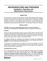
Optyma
™
Plus INVERTER
Stepless capacity modulation from 30 to 100 rps in a simple plug and play package
Application guidelines
2018
EcoDesign
cc.danfoss.com
Optyma
TM
by Danfoss


Content
Important information/Safety ................4
1.1 Symbols are shown left of the text ............. 4
Product description .................................5
2.1 Optyma
™
Plus INVERTER condensing unit ... 5
2.2 Exploded view Optyma
™
Plus INVERTER ..... 6
2.3 Condensing unit nomenclature system ... 7
2.4 Label ...................................................................... 7
2.5 Approvals and certificates ............................ 8
2.6 Technical specifications .................................. 8
2.7 Spare part codes ............................................... 8
2.8 Cooling capacities, sound data, power
consumption .............................................................9
2.9 Layout ..................................................................13
Application range...................................14
3.1 Main applications ............................................14
3.2 Condensing unit selection ..........................14
3.3 Application envelopes .................................15
3.4 Ambient conditions .......................................16
3.5 Limits for voltage supply .............................16
Installation ..............................................17
4.1 Location & fixings ............................................17
4.2 Electrical connection ....................................18
4.2.1 Power supply protection ..............................18
4.2.2 Protection and features ................................18
4.3 Wiring diagrams .............................................. 19
4.3.1 Emergency running without controller 20
4.4 Electrical protection standard (protection
class) ........................................................................... 23
4.5 EMC compliance ..............................................23
4.5.1 Warning when touching unit
when OFF .................................................................23
4.6 Phase sequence ..............................................24
4.7 Brazed connections........................................24
4.8 High pressure transmitter connection....25
System design recommendations .......26
5.1 Piping design .................................................. 26
5.2 Evacuation ......................................................... 27
5.3 Refrigerant charge .......................................... 28
5.4 Oil level ...............................................................29
5.5 Check before start ..........................................29
5.6 Startup of the unit ..........................................30
5.7 Check after start ..............................................30
Condensing unit controller ...................31
6.1 Advantages ........................................................31
6.2 Controller’s regulation logic ....................... 31
6.3 Functions ...........................................................31
6.4 Regulation reference for condensing
temperature .............................................................31
6.5 Fan operation ................................................... 31
6.6 Compressor control .......................................31
6.7 Maximum discharge gas temperature ....32
6.8 High pressure monitoring ...........................32
6.9 Low pressure monitoring .............................32
6.10 Pump down limit ...........................................32
6.11 Data communication ...................................32
6.12 Controller settings ........................................ 33
Service and maintenance ......................36
7.1 General recommendations .........................36
7.2 Condenser ......................................................... 36
7.3 Service and safety advice ............................. 36
7.4 Access ports ......................................................37
Transportation, handling and storage 38
8.1 Unpacking ..........................................................38
8.2 Transportation and handling .....................38
8.3 Disposal Instruction ....................................... 38
Warranty .................................................39
9.1 Warranty conditions ....................................... 39
9.2 Unauthorized changes ..................................39
Data collected during start up ..............40
3FRCC.PC.044.A5.02
Application Guidelines

There are 3 symbols, used for different degrees of
danger:
Warning! Risk of serious injury or death to person!
Caution! Danger which can lead to serious
damages!
Notice! Risk of damage to equipment!
This guideline is intended to enable users to
ensure the safe installation, starting, operation
and maintenance of Optyma
™
Plus INVERTER
condensing units. This guideline is not intended
to replace the system expertise available from
system manufacturers.
In addition to this instruction application
instructions of compressor drive, controller and
other internal components must be taken into
consideration as well.
1.1 Symbols are shown
left of the text
Important information/Safety
WARNING
CAUTION
NOTICE
4 FRCC.PC.044.A5.02
Application Guidelines

2.1 Optyma
™
Plus INVERTER
condensing unit
Optyma
™
Plus INVERTER combines our market
leading expertise in condensing unit design with
the unique benefits of stepless inverter scroll
technology. The result is 20-30% higher energy
efficiency in a flexible plug-and-play package,
for medium and high temperature refrigeration
applications in the range of 2kW to 9kW.
Standard equipment features:
• Variable speed compressor (scroll) with acoustic
housing and crankcase heater
• Compressor drive (with EMI filter)
• MCHX condenser
• Condenser fan motor
• Oil separator with oil heater
• Receiver with stop valve
• Ball valves
• Sight glass
• HP and LP switches
• Filter drier
• Optyma
™
Plus controller
• Circuit Breaker MCB, compressor contactor with
overload relay
• Robust weather proof housing
Product description
5FRCC.PC.044.A5.02
Application Guidelines

Product description
2.2 Exploded view
Optyma
™
Plus INVERTER
ENGINEERING CHANGE
REV
DATE
ALL DIMENSIONS IN MM UNLESS
OTHERWISE SPECIFIED
DRAWING No.
APPD
SCALE:NTS
C.N.No.
CHD
DRN
DRN
CHD
DATE NAME
REV
COPPER SYSTEM TUBING
TOLERANCE UNLESS OTHERWISE STATED BY DRAWING OR MFG. STANDARD
SHEET METAL
1.CUTTING SIZE 0.4mm
2.HOLE DIAMETER/SLOT
0.07mm
3.HOLES CENTER TO CENTER
0.2mm
4.ANGLES
2
5.HOLES/SLOT LOCATION 0.4mm
6.FORMED DIMENSIONS
0.8mm
1.LENGTH 25mm TO 1000mm
1.5mm
2.LENGTH ABOVE 1000mm
3.0mm
3.HOLES CENTER TO CENTER
2.0mm
4.HOLES LOCATION
5.0mm
5.ANGLES
2.0
6.UNSPECIFIED BENDS ARE 90
MAJOR
MINOR
SAFETY
SYMBOLS:
REVISION
CRITICAL
Confidential: Property of Danfoss Commercial Compressors. Not to be handed over to copied or used
by third party. Two or three dimensional reproduction of contents to be authorized by Danfoss CC.
21-12-2015 KLB
SHT 1 OF 1
EXPLODED-OP+EVO3_INV
EXPLODED VIEW INVERTER
H3
A
21-12-2015 RDG
21-12-2015 RDG
ITEM NAME DESCRIPTION QTY
1
023U8007
COMPONENT_ ADAPTER-FSA516M_DANFOSS 2
2
009G7053
COMPONENT, BALL VALVE GBC16S, DANFOSS 1
3
009G7054
COMPONENT, BALL VALVE GBC18S, DANFOSS 1
4
118A0614
COMPONENT, FILTER EN55011 1
5
118A0639C
COMPONENT, FLEXIBLE HOSE PIPE 1
6
118A0615
COMPONENT, FRIGO OIL SEPA 1.45L 1
7
HUSKY_118U3455_LEG
COMPONENT, FRIGO RCVR 6.2 L 1
8
061F8492
COMPONENT, HIGH PR SWITCH ACB-2UB463W, D 1
9
014F0174
COMPONENT, SIGHT GLASS SGN+ 16 INT-EXT 1
10
134N4263
COMPRESSOR DRIVE CDS803 7.5W 1
11
MLZ026_HOOD
COMPRESSOR JACKET 1
12
DIGITAL_DISPLY_2
DIGITAL DISPLAY 1
13
118A0679
ELECTRICAL, EMC FILTER FN2030 1
14
023Z8045
FILTER DRIER,DML083 1
15
118U3202
GRILLE H3 1
16
061F7283
LOW PR ACB 2UA418W DANFOSS 1
17
021F0075
MCHX 868*801*25.4 FPI 16 IN/OUT 1
18
118U3259
METAL, PNTD ACESS PNL H3 1
19
118U3243
METAL, PNTD FRONT COVER CNTRL BOX H3 1
20
118U3256
METAL, PNTD FRONT SIDE PNL H3 1
21
118U3258
METAL, PNTD LH SIDE PNL H3 1
22
118U3887
METAL, PNTD NEW FAN BRACKET H3 & H4 1
23
118U3255
METAL, PNTD PARTITION PNL H3 1
24
118U3261
METAL, UNPNTD BACK PNL H3 1
25
118U3241-02
METAL, UNPNTD BASE PNL H3 1
26
118U3264
METAL, UNPNTD TOP PNL H3 1
27
MANIFOLD_A6E500AJ0302
MOTOR, EBM 220W 50HZ 230V 1
28
118A0632001
PIPING DISCHARGE 1
29
118A05930001
PIPING OIL SEPA TO MCHE 1
30
118U3431001
PIPING RECEIVER TO DRIER 1
31
118U34320002
PIPING RECEIVER TO MCHE 1
32
118A06310001
PIPING SUCTION 1
33
PRESSURE_TRANSDUCER
PRESSURE TRANSDUCER 2
34
VZH028_035_044_INVERTER_SCROLL_
VVL028,035,044 INVERTER SCROLL 1
17
34
4
27
11
10
6
14
9
1
7
3
2
5
8
13
15
16
18
20
21
23
29
32
28
30
31
22
24
25
26
12
19
33
Legend:
1: FSA Adaptor
2: Liquid line valve (with schrader)
3: Suction line valve + Extra service
connection
4: EMI filter (drive)
5: Oil return pipe
6: Oil separator
7: Receiver
8: High pressure switch
9: Sight glass
10: Compressor drive
11: Acoustic hood
12: Optyma
™
Plus controller
13: EMI filter (controller)
14: Refrigerant filter
15: Fan guard
16: Low pressure switch
17: Microchannel heat exchanger
18: Right side door
19: E-box cover
20: Front door, right side
21: Unit frame
22: Fan bracket
23: Separation panel
24: Back panel
25: Base plate
26: Top panel
27: Fan assembly
28: Discharge pipe
29: Condenser outlet pipe
30: Receiver outlet pipe
31 Oil separator outlet pipe
32: Suction line
33: Rotalock valve
34: Compressor
6 FRCC.PC.044.A5.02
Application Guidelines

2018
EcoDesign
For more information related to EcoDesign compliance, please refer to Coolselector®
coolselector.danfoss.com or contact Danfoss
Product description
2.3 Condensing unit
nomenclature system
2.4 Label
OP - M P L M 028 VVL P01 E
1 2 3 4 5 6 7 8
1 Application M = MBP
2 Design P = Packaged units
3 Refrigerant
L = R404A, R407A, R407F
P= R404A, R407A, R407F, R448A, R449A
4 Condenser type
M = Standard with micro channel heat exchanger
Tambient max 43 deg C
5 Displacement 028 = 28 cm
3
/rev
6 Compressor platform VVL = variable speed scroll VLZ compressor
7 Version P01
8 Electrical code E = Compressor 400 V/3 phase/50 Hz, fan 230 V/1 phase/ 50 Hz
OP-MPPM044VVLP01E
Code Number.: 114X4334
Application MBP IP 54
Refrigerant (1) R448A/R449A/R407F
M.W.P HP (1) 28 bar (2)
LP (1) 7 bar (2)
Voltage 380V-400V~3N~50Hz
LRA Inverter Driven MCC 12.1 A
Serial No. 123456CG1015
MADE IN INDIA
A
B
C
D
E
F
G
H
R407A/R404A (2)
A: Model
B: Code number
C: Application
D: Refrigerant
E: Housing Service Pressure
F: Supply voltage, M§aximum Current Consumption
G: Serial Number and bar code
H: Protection
Serial-no.: XXXXXXCGWWYY
XXXXXX = ascending number
CG = manufacturing plant
WW = week of production
YY = year of production
7FRCC.PC.044.A5.02
Application Guidelines

Product description
All models OP-MPLM, OP-MPPM
All models OP-MPLM, OP-MPPM
Other Contact Danfoss
2.5 Approvals and
certificates
2.6 Technical
specifications
2.7 Spare part codes
Unit
Condenser coil
Condenser
fan
Receiver Dimensions Weight [kg]
Type
Air flow
[m
3
/h]
Internal
volume
[dm
3
]
Fan blade
Ø [mm]
Volume [L]
(without
valve)
Depth
D
[mm]
Width
W
[mm]
Height
H
[mm]
Suction line Liquid line Gross Net
OP-MPLM028
OP-MPPM028
G7 5200 1.62 1x500 6.2 481 1406 965 3/4" 5/8" 150 124
OP-MPLM035
OP-MPPM035
G7 5200 1.62 1x500 6.2 481 1406 965 3/4" 5/8" 151 125
OP-MPLM044
OP-MPPM044
G7 5200 1.62 1x500 6.2 481 1406 965 3/4" 5/8" 151 125
Unit
MCC compressor
[A]
400V/3phase
Max cont. power
consumption [kW]
MCC Fan
[A]
230V/1 phase
Fan power
output
[W]
Fan power
consumption
[W]
OP-MPLM028
OP-MPPM028
8.1 3.98 0.96 1x130 1x220
OP-MPLM035
OP-MPPM035
9.8 4.94 0.96 1x130 1x220
OP-MPLM044
OP-MPPM044
12.0 6.33 0.96 1x130 1x220
Unit Compressor Condenser
Fan
assembly
Receiver Filter
Sight
glass
Liquid
line
valve
Suction
line
valve
High
pressure
transmitter
Low
pressure
transmitter
Suction
and
ambient
temperature
Discharge
temperature
sensor
Fan grill
OP-MPLM028
OP-MPPM028
120G0162 118U3494 118U3829 118U3476 023Z5045 014F0174 009G7053 009G7054 118U3722 118U3721 084N0003 084N2007 118U3485
OP-MPLM035
OP-MPPM035
120G0159 118U3494 118U3829 118U3476 023Z5045 014F0174 009G7053 009G7054 118U3722 118U3721 084N0003 084N2007 118U3485
OP-MPLM044
OP-MPPM044
120G0156 118U3494 118U3829 118U3476 023Z5045 014F0174 009G7053 009G7054 118U3722 118U3721 084N0003 084N2007 118U3485
Unit Controller* Main switch
Compressor
contact
Door
handle
Crankcase
heater
High
pressure
switch
Low
pressure
switch
Acoustic
hood
Compres-
sor drive
CDS803
EMI
filter
(Drive)
EMI filter
(Controller)
Compressor
oil
Oil
separator
OP-MPLM028
OP-MPPM028
118U3465 118U3852 118U3847 118U3858 120Z5040 118U3718 118U3720 120Z5043 118U3973 118U3972 118U3974
120Z5034
120Z0648
118U3981
OP-MPLM035
OP-MPPM035
118U3465 118U3852 118U3847 118U3858 120Z5040 118U3718 118U3720 120Z5043 118U3973 118U3972 118U3974
120Z5034
120Z0648
118U3981
OP-MPLM044
OP-MPPM044
118U3465 118U3852 118U3847 118U3858 120Z5040 118U3718 118U3720 120Z5043 118U3973 118U3972 118U3974
120Z5034
120Z0648
118U3982
Unit Top panel Fan Panel Back panel Front panel Access panel Left side panel
OP-MPLM028
OP-MPPM028
118U5131 118U5132 118U5133 118U5134 118U5135 118U5165
OP-MPLM035
OP-MPPM035
118U5131 118U5132 118U5133 118U5134 118U5135 118U5165
OP-MPLM044
OP-MPPM044
118U5131 118U5132 118U5133 118U5134 118U5135 118U5165
* For service replacement of controller in Optyma
™
Plus INVERTER only new version of controller can be used: code number on the
controller is 084B8080.
For service purpose original components (spare parts) recommended by Danfoss should be used.
NOTICE
8 FRCC.PC.044.A5.02
Application Guidelines

2018
EcoDesign
For more information related to EcoDesign compliance, please refer to Coolselector®
coolselector.danfoss.com or contact Danfoss
Product description
2.8 Cooling capacities, sound data, power consumption
Optyma
™
Plus INVERTER, R407A
Model number
Code
number
Compressor
Compressor
speed, rps
Tamb [°C]
Cooling capacity Q [kW] P [kW] EcoDesign (2)
Sound power
level dB(A)
Sound pressure
level 10 m dB(A)
Te [°C]
COP
(1)
Q [kW] P [kW] COP
A
SEPR
-15 C -10 C -5 C 0 C 5 C -10°C
OP-MPPM028VVLP01E 114X4302 VLZ028TGA
30
27 1435 1797 2227 2732 3320
72.8 41.8
32 1345 1686 2092 2570 3128 899 1.88
38 - 1557 1934 2380 2902
43 - - - - -
50
27 2382 2994 3711 4543 5499
73.4 42.4
32 2243 2829 3515 4310 5224 1333 2.12
38 - 2622 3267 4015 4876
43 - 2442 3050 3757 4571
75
27 3499 4412 5470 6686 8069
74.0 43.0
32 3306 4177 5183 6339 7654 2005 2.08
38 - 3879 4821 5901 7131
43 - 3618 4503 5519 6676
100
27 4549 5740 7106 8660 10413
75.3 44.3
32 4313 5438 6726 8192 9847 2830 1.92 5539 2834 1.95 3.49
38 - 5067 6261 7621 9158
43 - 4747 5864 7135 8575
OP-MPPM035VVLP01E 114X4316 VLZ035GA
30
27 1806 2259 2796 3426 4157
71.7 40.7
32 1692 2119 2626 3223 3916 1057 2.00
38 - 1956 2427 2983 3632
43 - - - - -
50
27 2988 3751 4643 5674 6854
72.3 41.3
32 2812 3542 4393 5378 6504 1599 2.22
38 - 3279 4079 5003 6061
43 - 3051 3803 4674 5674
75
27 4374 5503 6805 8291 9973
72.9 41.9
32 4128 5203 6439 7849 9443 2445 2.13
38 - 4824 5977 7292 8779
43 - 4492 5573 6806 8201
100
27 5666 7124 8782 10652 12744
74.6 43.6
32 5367 6741 8302 10064 12035 3488 1.93 6876 3494 1.97 3.63
38 - 6270 7715 9345 11172
43 - 5864 7212 8734 10442
OP-MPPM044VVLP01E 114X4334 VLZ044GA
30
27 2303 2877 3556 4350 5268
72.6 41.6
32 2159 2699 3339 4091 4962 1278 2.11
38 - 2491 3085 3785 4600
43 - - - - -
50
27 3796 4757 5876 7163 8629
73.1 43.1
32 3569 4487 5553 6779 8175 1974 2.27
38 - 4148 5146 6294 7602
43 - 3852 4790 5870 7101
75
27 5527 6933 8542 10363 12405
73.7 43.7
32 5208 6543 8067 9790 11720 3073 2.13
38 - 6052 7468 9069 10862
43 - 5620 6944 8440 10117
100
27 7125 8914 10926 13170 15649
74.4 43.4
32 6738 8421 10311 12419 14750 4434 1.90 8612 4446 1.94 3.71
38 - 7813 9557 11502 13656
43 - 7288
8911 10721 12728
SEPR, Seasonal Energy Performance Ratio
Q [W], Cooling Capacity
P [W], Power Input
[1] Nominal conditions, Evaporating temperature -10°C. Ambient air temperature +32°C. Superheat 10K.
[2] Rated conditions, Evaporating temperature -10°C. Ambient air temperature +32°C. Return Gas Temperature 20°C
9FRCC.PC.044.A5.02
Application Guidelines

2018
EcoDesign
For more information related to EcoDesign compliance, please refer to Coolselector®
coolselector.danfoss.com or contact Danfoss
Optyma
™
Plus INVERTER, R407F
Product description
Model number
Code
number
Compressor
Compressor
speed, rps
Tamb [°C]
Cooling capacity Q [kW] P [kW] EcoDesign (2)
Sound power
level dB(A)
Sound pressure
level 10 m dB(A)
Te [°C]
COP
(1)
Q [kW] P [kW] COP
A
SEPR
-15 C -10 C -5 C 0 C 5 C -10°C
OP-MPPM028VVLP01E 114X4302 VLZ028TGA
30
27 1534 1915 2363 2888 3496
71.7 40.7
32 1447 1808 2234 2733 3313 945 1.91
38 - 1679 2078 2547 3092
43 - - - - -
50
27 2598 3258 4022 4900 5902
72.3 41.3
32 2450 3083 3815 4655 5613 1410 2.19
38 - 2862 3555 4349 5254
43 - 2669 3328 4083 4943
75
27 3826 4792 5901 7163 8590
72.9 41.9
32 3612 4539 5600 6806 8169 2121 2.14
38 - 4220 5223 6362 7647
43 - 3942 4895 5977 7197
100
27 4950 6174 7573 9158 10939
74.2 43.2
32 4689 5857 7191 8703 10400 2977 1.97 5905 2979 1.98 3.58
38 - 5470 6724 8145 9742
43 - 5141 6327 7671 9182
OP-MPPM035VVLP01E 114X4316 VLZ035TGA
30
27 1931 2408 2969 3623 4380
71.2 40.2
32 1820 2272 2805 3428 4149 1115 2.04
38 - 2110 2609 3193 3871
43 - - - - -
50
27 3258 4080 5029 6116 7351
71.9 40.9
32 3069 3858 4766 5804 6984 1698 2.27
38 - 3577 4435 5416 6529
43 - 3330 4147 5078 6135
75
27 4776 5970 7334 8878 10612
72.5 41.5
32 4503 5648 6951 8425 10079 2594 2.18
38 - 5242 6472 7860 9417
43 - 4888 6055 7372 8847
100
27 6156 7655 9358 11274 13409
73.55 42.5
32 5825 7254 8876 10699 12731 3679 1.97 7326 3682 1.99 3.71
38 - 6764 8286 9996 11902
43 - 6347 7783 9397 11198
OP-MPPM044VVLP01E 114X4334 VLZ044TGA
30
27 2464 3068 3778 4603 5555
72 41
32 2322 2895 3568 4354 5260 1353 2.14
38 - 2686 3316 4052 4903
43 - - - - -
50
27 4135 5170 6359 7714 9244
72.6 41.6
32 3891 4882 6019 7311 8771 2105 2.32
38 - 4519 5591 6809 8184
43 - 4200 5218 6374 7677
75
27 6024 7510 9195 11089 13196
73.2 42.2
32 5670 7092 8700 10503 12509 3271 2.17
38 - 6567 8080 9774 11658
43 - 6107 7540 9143 10924
100
27 7723 9567 11641 13951 16496
74 43
32 7298 9052 11023 13215 15631 4694 1.93 9164 4701 1.95 3.78
38 - 8421 10265 12315 14574
43 - 7884
9618 11548 13675
SEPR, Seasonal Energy Performance Ratio
Q [W], Cooling Capacity
P [W], Power Input
[1] Nominal conditions, Evaporating temperature -10°C. Ambient air temperature +32°C. Superheat 10K.
[2] Rated conditions, Evaporating temperature -10°C. Ambient air temperature +32°C. Return Gas Temperature 20°C
10 FRCC.PC.044.A5.02
Application Guidelines

2018
EcoDesign
For more information related to EcoDesign compliance, please refer to Coolselector®
coolselector.danfoss.com or contact Danfoss
Model number
Code
number
Compressor
Compressor
speed, rps
Tamb [°C]
Cooling capacity Q [kW] P [kW] EcoDesign (2)
Sound power
level dB(A)
Sound pressure
level 10 m dB(A)
Te [°C]
COP
(1)
Q [kW] P [kW] COP
A
SEPR
-15 C -10 C -5 C 0 C 5 C -10°C
OP-MPPM028VVLP01E 114X4302 VLZ028TGA
30
27 1597 1990 2446 2972 3573
71.2 40.2
32 1484 1854 2284 2780 3349 1002 1.85
38 - - - - -
43 - - - - -
50
27 2700 3340 4080 4929 5894
71.9 40.9
32 2505 3106 3802 4601 5510 1537 2.02
38 2266 2820 3168 4198 5039
43 2060 2574 3168 3853 4636
75
27 3994 4916 5976 7181 8542
72.5 41.5
32 3707 4574 5569 6701 7981 2349 1.95
38 3354 4151 4633 6110 7290
43 3048 3785 4633 5600 6698
100
27 5202 6381 7724 9241 10939
73.7 42.7
32 4832 5939 7198 8620 10214 3317 1.79 6250 3328 1.88 3.47
38 4368 5384 5965 7845 9310
43 3962 4899 5965 7171 8528
OP-MPPM035VVLP01E 114X4316 VLZ035TGA
30
27 2027 2517 3085 3739 4485
73.1 42.1
32 1878 2339 2875 3491 4196 1159 2.02
38 - - - - -
43 - - - - -
50
27 3402 4193 5108 6153 7338
73.8 42.8
32 3158 3899 4755 5735 6846 1794 2.17
38 2854 3533 3937 5215 6236
43 2590 3215 3937 4766 5711
75
27 4962 6087 7381 8853 10511
74.4 43.4
32 4610 5659 6866 8240 9790 2813 2.01
38 4169 5126 5672 7481 8899
43 3784 4662 5672 6826 8133
100
27 6354 7768 9389 11226 13287
75.4 44.4
32 5901 7218 8727 10438 12360 4070 1.77 7614 4088 1.86 3.77
38 5331 6529 7183 9460 11214
43 4828 5926 7183 8614 10227
OP-MPPM044VVLP01E 114X4334 VLZ044TGA
30
27 2620 3236 3949 4767 5698
73.1 42.1
32 2426 3008 3681 4453 5334 1391 2.16
38 - - - - -
43 - - - - -
50
27 4322 5303 6426 7700 9134
73.9 42.9
32 4012 4932 5987 7183 8532 2288 2.16
38 3623 4470 4964 6541 7784
43 3284 4067 4964 5985 7139
75
27 6267 7656 9231 10997 12960
74.5 43.5
32 5812 7111 8583 10234 12070 3618 1.97
38 5243 6432 7078 9289 10972
43 4744 5839 7078 8472 10027
100
27 8008 9755 11715 13888 16273
75.5 44.5
32 7406 9033 10856 12879 15102 5190 1.74 9560 5220 1.83 3.76
38 6648 8128 8852 11626 13651
43 5980 7335
8852 10539 12399
SEPR, Seasonal Energy Performance Ratio
Q [W], Cooling Capacity
P [W], Power Input
[1] Nominal conditions, Evaporating temperature -10°C. Ambient air temperature +32°C. Superheat 10K.
[2] Rated conditions, Evaporating temperature -10°C. Ambient air temperature +32°C. Return Gas Temperature 20°C
Optyma
™
Plus INVERTER, R404A
Product description
11FRCC.PC.044.A5.02
Application Guidelines

2018
EcoDesign
For more information related to EcoDesign compliance, please refer to Coolselector®
coolselector.danfoss.com or contact Danfoss
Optyma
™
Plus INVERTER, R448A/R449A
Product description
Model number
Code
number
Compressor
Compressor
speed, rps
Tamb [°C]
Cooling capacity Q [kW] P [kW] EcoDesign (2)
Sound power
level dB(A)
Sound pressure
level 10 m dB(A)
Te [°C]
COP
(1)
Q [kW] P [kW] COP
A
SEPR
-15 C -10 C -5 C 0 C 5 C -10°C
OP-MPPM028VVLP01E 114X4302 VLZ028TGA
30
27 1465 1839 2276 2783 3365
71.2 40.2
32 1375 1732 2149 2633 3190 939 1.84
38 - - - - -
43 - - - - -
50
27 2494 3107 3816 4629 5553
71.9 40.9
32 2346 2930 3605 4379 5259 1415 2.07
38 - 2706 3338 4064 4891
43 - 2510 3106 3790 4571
75
27 3656 4527 5536 6695 8013
72.5 41.5
32 3443 4270 5226 6324 7573 2159 1.98
38 - 3949 4842 5866 7032
43 - 3670 4509 5472 6569
100
27 4686 5774 7041 8502 10171
73.7 42.7
32 4421 5451 6648 8028 9605 3054 1.78 5548 3058 1.81 3.38
38 - 5056 6170 7454 8922
43 - 4713 5761 6967 8346
OP-MPPM035VVLP01E 114X4316 VLZ035TGA
30
27 1836 2301 2845 3476 4201
73.1 42.1
32 1722 2166 2684 3284 3974 1081 2.00
38 - - - - -
43 - - - - -
50
27 3091 3846 4713 5699 6812
73.8 42.8
32 2896 3616 4442 5381 6441 1748 2.07
38 - 3327 4102 4983 5977
43 - 3076 3806 4637 5577
75
27 4505 5569 6792 8183 9752
74.4 43.4
32 4227 5238 6396 7713 9200 2718 1.93
38 - 4827 5907 7136 8523
43 - 4472 5487 6641 7945
100
27 5773 7090 8615 10361 12338
75.4 44.4
32 5439 6683 8119 9765 11631 3839 1.74 6814 3837 1.78 3.29
38 - 6185 7518 9045 10779
43 - 5757 7006 8436 10061
OP-MPPM044VVLP01E 114X4334 VLZ044TGA
30
27 2364 2954 3637 4422 5317
73.1 42.1
32 2213 2776 3429 4180 5037 1316 2.11
38 - - - - -
43 - - - - -
50
27 3894 4834 5915 7145 8532
73.9 42.9
32 3650 4544 5570 6739 8058 2051 2.22
38 - 4185 5144 6238 7473
43 - 3876 4779 5808 6973
75
27 5674 7003 8510 10203 12087
74.5 43.5
32 5308 6572 8003 9609 11397 3243 2.03
38 - 6034 7371 8873 10544
43 - 5566 6825 8237 9810
100
27 7289 8959 10828 12899 15173
75.5 44.5
32 6786 8375 10149 12112 14265 4739 1.77 8558 4753 1.8 3.73
38 - 7634 9291 11123 13130
43 - 6982
8539 10260 12145
SEPR, Seasonal Energy Performance Ratio
Q [W], Cooling Capacity
P [W], Power Input
[1] Nominal conditions, Evaporating temperature -10°C. Ambient air temperature +32°C. Superheat 10K.
[2] Rated conditions, Evaporating temperature -10°C. Ambient air temperature +32°C. Return Gas Temperature 20°C
12 FRCC.PC.044.A5.02
Application Guidelines

Product description
2.9 Layout
OP-MPLM028-035-044, OP-MPPM028-035-044
13FRCC.PC.044.A5.02
Application Guidelines

Application range
3.1 Main applications
3.2 Condensing unit
selection
Optyma
™
Plus INVERTER is a perfect cooling
solution for typical MBP applications like food
retail, petrol forecourt sites, cold rooms ,and
display cases. All units are fully wired and factory
tested. They have one cabinet sizes and are
equipped with one fan.
Optyma
™
Plus INVERTER outdoor condensing
units are released for R448A/R449A, R407A/F and
R404A.
Inverter technology offers more flexibility in
condensing unit selection than fixed-speed units.
Selection of the right inverter condensing unit
size can be made by next method:
Select a condensing unit size which achieves the
peak load system cooling capacity demand at its
maximum speed.
NOTICE
It is compulsory to secure that
condensing unit capacity at minimum speed
(30 rps) will not be higher than necessary
cooling capacity for the smallest evaporator!
In case minimum (at 30 rps) condensing unit
capacity is higher than capacity of smallest
evaporator it can cause work of condensing
unit outside its application envelope and as
consequence reduce lifetime.
Example1 (evaporating temperature -10 °C,
ambient temperature 32 °C, R404A):
Evaporator1= 3 kW
Evaporator2= 3 kW
Evaporator3= 3 kW
Total Q = 9 kW (maximum cooling capacity)
Minimum cooling capacity = minimum
evaporator capacity = minimum evaporating
capacity = 3kW
According to the capacities at evaporating -10 °C,
ambient 32 °C and refrigerant R404A condensing
unit OP-MPPM044 (maximum capacity 9 kW)
achieves the peak load system cooling capacity
(9,3 kW) demand at its maximum speed and
at the same time condensing unit capacity at
minimum speed (minimum capacity 3 kW) is not
higher than necessary cooling capacity for the
smallest evaporator (3 kW).
Example2 (evaporating temperature -10 °C,
ambient temperature 32 °C, R404A):
Evaporator1= 1 kW
Evaporator2= 2,1 kW
Evaporator3= 2,5 kW
Evaporator4=1,5 kW
Total Q = 7,1 kW (maximum cooling capacity)
Minimum cooling capacity = minimum
evaporator capacity = Evaporator1 = 1 kW.
According to the capacities at evaporating -10 °C,
ambient 32 °C and refrigerant R404A condensing
unit OP-MPPM035 (maximum capacity 7,2 kW)
achieves the peak load system cooling capacity
(7,1 kW) demand at its maximum speed but
at the same time condensing unit capacity at
minimum speed (minimum capacity 2,3 kW) is
higher than necessary cooling capacity for the
smallest evaporator (1 kW).
In this case it is recommended to connect
few evaporators together (regulated by one
thermostat) to achieve smallest required capacity
higher than minimum capacity of condensing
unit: by managing Evaporator1 and Evaporator4
via one thermostat minimum required capacity
will be 2,5 kW (Evaporator2) which is higher than
minimum capacity of condensing unit at low
speed (2,3 kW).
NOTICE
Compressor of Optyma™ Plus
INVERTER is equipped with a IPM (Interior
Permanent Magnet) motor. The compressor
cannot operate without frequency converter.
It will be destroyed immediately if connected
directly to public network. The applied frequency
from the inverter will be 60 Hz for 30 rps (1800
rpm) up to 200 Hz for 100 rps (6000 rpm).
Please refer to the table below
Compressor speed Min Max
rps 30 100
rpm 1800 6000
Drive output frequency Hz 60 200
14 FRCC.PC.044.A5.02
Application Guidelines

Application range
3.3 Application envelopes
The operating envelopes of Optyma
™
Plus
INVERTER are given in the figures below, where
the ambient and evaporating temperatures
represent the range for steady state operation.
The figures below show the operating envelopes
for condensing units with refrigerants R448A/
R449A, R407A/F and R404A. The operating limits
serve to define the envelopes within which
reliable operation of the condensing units are
guaranteed.
0
10
20
30
40
50
60
5
15
25
35
45
55
Ambient temperature (°C)
Operating Map (R407F/A)
-20 -10 0 10 20-25 -15 -5 5 15
Evaporating temperature (°C)
30 rps-100 rps
SH10K
50 rps-100 rps
°C
(Te -10°C, Tamb 43°C)
0
10
20
30
40
50
60
5
15
25
35
45
55
Ambient temperature (°C)
Operating Map (R404A)
-20 -10 0 10 20-25 -15 -5 5 15
Evaporating temperature (°C)
30 rps-100 rps
SH10K
50 rps-100 rps
°C
(Te -15°C, Tamb 43°C)
0
10
20
30
40
50
60
5
15
25
35
45
55
Ambient temperature (°C)
Operating Map (R448A/R449A)
-20 -10 0 10 20-25 -15 -5 5 15
Evaporating temperature (°C)
30 rps-100 rps
SH 10K
50 rps-100 rps
°C
(Te -10°C, Tamb 43°C)
15FRCC.PC.044.A5.02
Application Guidelines

Minimum and maximum evaporating and
condensing temperatures as per the operating
envelopes – compressor should work inside
application envelope.
Special attention to suction line insulation will
have to be secured in order to:
• Avoid too high superheat during high ambient
conditions that can create too high discharge
gas temperature.
• Avoid too low superheat during low ambient
conditions that can create condensation of
refrigerant in suction line.
Other operating limits: Recommendation
Discharge gas temperature
125
°C maximum
Evaporator outlet superheat above 6K (to avoid liquid flood back)
Suction gas superheat at compressor inlet within the limits shown on the application envelope
Application range
3.4 Ambient conditions
3.5 Limits for voltage
supply
Optyma
™
Plus INVERTER units can be used with
ambient temperature from -15°C to 43°C. For
altitudes above 2000 m, contact Danfoss. The
other working conditions should be within the
limits of application envelope.
To assure that the unit can start during cold
conditions the parameter “c94 LpMinOnTime” can
be used. If this parameter is set to a value that
is higher than 0 and the ambient temperature
(Tamb) is below 5°C, the internal transmitter “LP
switch c75” and “pump down limit c33” will be
overridden for the number of seconds defined
in “c94 LpMinOnTime”. And the value for Min on
time for the compressor will be set to the largest
of the values of “c94 MinLpOnTime” and “c01 Min.
on time”.
The CDS803 drive forces the compressor to 50rps
(see Optyma Controller parameter c47) for 30s
always at compressor start, to ensure proper oil
return at low load and short runtimes. The start
delay time can be modified via drive parameter
1-71, if a proper oil return is always ensured
without or by modifying this start delay function.
In order to change 1-71, a separate LCP panel
needs used to change the settings on the drive,
the LCP panel has the ordering code 120Z0581.
When changing 1-71, a value not lower as 10
seconds should get applied.
Voltage limits: Min: 360 V Max 440 V
Phase asymmetry: ±3%
Frequency limits: 50Hz ±1%
Red line on the application envelope indicates
maximum safe ambient temperature for low load
(30-50 rps) and high ambient conditions (above
32 °C for R448A/R449A, 32 °C for R404A and
above 40 °C for R407A/F.
In case low unit capacity required (30-50 rps)
at high ambient temperatures controller will
increase compressor speed up to minimum safe
speed at high temperature. This minimum safe
speed at high temperature is factory preset to
50 rps (controller parameter c47: Start speed
of the compressor). It is not recommended to
decrease setting of parameter c47 below 50 rps
as this can lead to work of compressor at low
speed during high ambient conditions which can
reduce lifetime of the unit.
16 FRCC.PC.044.A5.02
Application Guidelines

CAUTION
Optyma
™
Plus INVERTER unit
has to be installed by competent authorized
personnel and the installation shall comply to
applicable local laws and rules.
Installation
4.1 Location & fixings
The unit is to be placed in such a way that it is
not blocking or expose an obstacle for walking
areas, doors, windows etc. The foundation where
the unit is to be placed upon has to be strong
enough to carry the entire weight, see unit
data. Ensure adequate space around the unit
for air circulation. Avoid installing the unit in
locations which are exposed to direct sunshine
daily for long periods. Unit has to be placed on
a horizontal surface - less than 3° slope, which
has to be strong and stable enough to eliminate
vibrations and interference. It is recommended to
install the unit on rubber grommets or vibration
dampers (not part of the Danfoss supply).
Installation of unit shall not be done in aggressive
and dusty environments.
Furthermore the installation of the unit shall not
be done in facilities containing flammable gasses
or in installation containing flammable gasses.
NOTICE
Special attention should be paid if
unit needs to be installed close to the sea as this
can reduce unit lifetime due to corrosion of metal
parts.
Where multiple units are to be installed in the
same location, please consider each individual
case carefully. Air by-pass around each condenser
and between the units should be avoided at all
times.
Optyma
™
Plus INVERTER condensing units can
also be used for wall mounting on suitable
brackets. Wall mounting brackets are not
supplied by Danfoss.
Another factor to consider in finding a good
installation site is the direction of the prevailing
wind. For example if the air leaving the condenser
faces the prevailing wind, the air flow through
the condenser can be impeded, causing high
condensing temperatures, improper functioning
of the unit and ultimately resulting in reducing
the life of the unit. A baffle is a remedy for this
situation.
W
Q
R
X
ZY
Q: Air in R: Air out
Unit
W
[mm]
X
[mm]
Y
[mm]
Z
[mm]
Housing 3 250 760 580 580
Picture 1: Minimum mounting distances
17FRCC.PC.044.A5.02
Application Guidelines

Installation
4.2 Electrical connection
WARNING
Ensure that power supply
cannot be switched on during installation.
Below table lists recommended wiring sizes for
the condensing unit power supply cables. These
wiring sizes are valid for a cable length up to 30 m.
Note: 1.The wire size here is the guideline. In
each specific case required cable size should be
specified by the installer depending on the system
design, ambient temperature, the wire material,
current, etc.
In order to ensure a safe and problem free
operation of the unit it is recommended to:
- Ensure that the power supply corresponds to
the unit and that the power supply is stable (see
nominal values on unit label and power supply
limits in paragraph 3.5).
- Make the power supply according to present
norm and legal requirements. Ensure that the
unit is properly connected to ground.
The unit is equipped with a main switch with
overload protection. Overload protection is preset
from factory. Value for overload protection can be
found in the wiring diagram. Wiring diagram can
be found in front door of unit. Unit is equipped
with high and low pressure switches, which
directly cuts the power supply of the compressor
contactor in case of activation.
Unit is equipped with an electronic controller and
compressor drive.
The controller and compressor drive are pre-
programmed with parameters ready for use with
the actual unit.
As standard the parameters for operation with
refrigerant R449A set. If another refrigerant is
to be used refrigerant parameter (o30) needs to
be changed (refer to description in Controller
application manual). Parameters for high and
low pressure cut outs are preset in the controller
adapted to the compressor and refrigerant
installed in the unit.
Model Cable size, mm
2
(from network to unit main switch)
OP-MPLM028
OP-MPPM028
4
OP-MPLM035
OP-MPPM035
4
OP-MPLM044
OP-MPPM044
4
You should use only original circuit breaker,
min. short circuit breaking capacity needs to
be 100kA. Please refer to spare part section for
selection of components for service replacement.
- Electronic thermal compressor protection against
overload.
- Temperature monitoring of the heat sink ensures
that the frequency converter trips in case of
overtemperature.
- The frequency converter is protected against
short-circuits between compressor terminals
U, V, W.
- When a compressor phase is missing, the
frequency converter trips and issues an alarm.
- When a mains phase is missing, the frequency
converter trips or issues a warning (depending
on the load).
- Monitoring of the intermediate circuit voltage
ensures that the frequency converter trips, when
the intermediate circuit voltage is too low or too
high.
- The frequency converter is protected against
ground faults on compressor terminals U, V, W.
- Occurring alarms will be shown in the controller
display and by the red LED in front of the
frequency converter.
- The root cause of an individual alarm can be
shown with an optional LCP (local control panel,
code 120Z0581) or the MCT10 setup software.
4.2.1 Power supply
protection
4.2.2 Protection and
features
18 FRCC.PC.044.A5.02
Application Guidelines

Installation
4.3 Wiring diagrams
OP-MPLM028-035-044, OP-MPPM028-035-044
A1 : EMC/RFI Filter (Compressor) A2 : Frequency Converter A3 : EMI Filter (Controls) A4 : Optyma
™
Plus Controller
B1 : Condensing Pressure Transducer B2 : Suction Pressure Transducer B3 : High Pressure Switch B4 : Low Pressure Switch
C1 : Run Capacitor (Fan) F1 : Fuse (Control Circuit) K1 : Contactor M1 : Compressor
M2 : Fan Motor Q1 : Main Switch R1 : Ambient Temp. Sensor R2 : Discharge Temp. Sensor
R3 : Suction Temp. Sensor R4,R5 : Auxiliary Temp. Sensor (optional) R6 : Crankcase Heater R7 : Oil Separator Heater
S1 : Room Thermostat (optional) X1 : Terminal
Supply : Supply Fan : Fan Alarm : Alarm Comp. : Compressor
CCH : Crankcase Heater Aux : Auxiliary
19FRCC.PC.044.A5.02
Application Guidelines

Installation
4.3.1 Emergency running
without controller
In case of controller failure, the condensing unit
can still be operated when the controller standard
wiring (WD1) is modified into a temporary wiring
(WD2) as described below.
This modification may be done by authorized
electricians only. Country legislations have to be
followed.
Disconnect the condensing unit from power
supply (turn hardware main switch off).
• Contact of Room Thermostat must be possible to
switch 250VAC.
• Remove wire 22 (safety input DI3) and wire 6 (fan
supply) and put them together. A fan pressure
switch (e.g. KP5) or a fan speed controller (e.g.
XGE) can be connected in series to wire 6.
• Remove wire 10 (drive start) and wire 24 (room
thermostat) and put them together.
• Remove wire 11 (drive start) and wire 25 (room
thermostat) and put them together.
• Remove wire 53 and 55 from drive terminals and
connect the attached 10kOhm potentiometer
(R8) as below:
wire 1 to drive terminal 55
wire 2 to drive terminal 53
wire 3 to drive terminal 50
• Turn the knob of the potentiometer to middle
position, which corresponds approximately
compressor speed 50rps.
• Remove wire 14 (crankcase and oil separator
heaters) and connect it to the compressor
contactor terminal 22.
• Remove wire 12 (supply crankcase and oil
separator heaters), extend this wire by using an
250 Vac 10mm² terminal bridge and 1,0mm²
brown cable and connect it to compressor
contactor terminal 21.
• Remove the large terminal block from the
controller terminals 10 to 19.
• Connect the condensing unit to power supply
(turn hardware main switch on).
• Adjust the potentiometer to get the desired
speed.
• Replace the controller as soon as possible.
20 FRCC.PC.044.A5.02
Application Guidelines
/