Page is loading ...

Solar-Powered
Wireless
Repeater
USER
MANUAL
Davis Instruments, 3465 Diablo Avenue, Hayward, CA 94545-2778 U.S.A. • 510-732-9229 • www.davisnet.com
R
For Vantage Pro2™, Vantage Vue®,
Weather Envoy
™, Envoy8X™,
and Vantage Connect
®
Product number 7627

Transmitter and Repeater ID Worksheet
List the transmitter types and circle the transmitter IDs used:
Circle last Repeater ID used:
ABCDEF GH
Transmitter Type Transmitter ID
1
2
3
4
5
6
7
8

i
Table of Contents
Wireless Repeater Overview
Included Components and Hardware . . . . . . . . . . . . . . . . . . . . . . . . . . . . . . . . . . . . . 1
Repeater Board Contents. . . . . . . . . . . . . . . . . . . . . . . . . . . . . . . . . . . . . . . . . . . . . . . 2
Wireless Repeater Introduction. . . . . . . . . . . . . . . . . . . . . . . . . . . . . . . . . . . . . . . . . . 4
Wireless Repeater Installation Overview . . . . . . . . . . . . . . . . . . . . . . . . . . . . . . . . . . 5
Repeater Configuration/Architecture
Repeater Architecture . . . . . . . . . . . . . . . . . . . . . . . . . . . . . . . . . . . . . . . . . . . . . . . . . 6
Single Repeater Configuration . . . . . . . . . . . . . . . . . . . . . . . . . . . . . . . . . . . . . . . . . . 7
Advanced Repeater Configurations . . . . . . . . . . . . . . . . . . . . . . . . . . . . . . . . . . . . . . 7
Applying Power . . . . . . . . . . . . . . . . . . . . . . . . . . . . . . . . . . . . . . . . . . . . . . . . . . . . . . 11
Single Repeater Installation
Verify Transmitter ID . . . . . . . . . . . . . . . . . . . . . . . . . . . . . . . . . . . . . . . . . . . . . . . . 12
Verifying Repeater ID. . . . . . . . . . . . . . . . . . . . . . . . . . . . . . . . . . . . . . . . . . . . . . . . 14
Verifying Communication with a Transmitter . . . . . . . . . . . . . . . . . . . . . . . . . . . . . 14
Choosing a Location . . . . . . . . . . . . . . . . . . . . . . . . . . . . . . . . . . . . . . . . . . . . . . . . . 17
Testing a Proposed Location . . . . . . . . . . . . . . . . . . . . . . . . . . . . . . . . . . . . . . . . . . . 17
Advanced Repeater Installation
Multiple Repeater (Daisy-Chain) Installation . . . . . . . . . . . . . . . . . . . . . . . . . . . . . . 18
Multiple Transmitters/One Repeater Installation . . . . . . . . . . . . . . . . . . . . . . . . . . . 21
Combination Network (Multiple Transmitters/Repeaters) Installation . . . . . . . . . . 24
Choosing Locations. . . . . . . . . . . . . . . . . . . . . . . . . . . . . . . . . . . . . . . . . . . . . . . . . . 27
Testing Proposed Locations . . . . . . . . . . . . . . . . . . . . . . . . . . . . . . . . . . . . . . . . . . . 27
Mounting the Wireless Repeater
General Installation Guidelines. . . . . . . . . . . . . . . . . . . . . . . . . . . . . . . . . . . . . . . . . 28
Installing the Repeater on a Flat Surface . . . . . . . . . . . . . . . . . . . . . . . . . . . . . . . . . 28
Installing the Repeater on a Pole. . . . . . . . . . . . . . . . . . . . . . . . . . . . . . . . . . . . . . . . 29
Console and WeatherLink Configuration . . . . . . . . . . . . . . . . . . . . . . . . . . . . . . . . . 30
Repeater Information on the Console . . . . . . . . . . . . . . . . . . . . . . . . . . . . . . . . . . . . 30
Repeater Functionality in WeatherLink . . . . . . . . . . . . . . . . . . . . . . . . . . . . . . . . . . 31
Maintenance and Troubleshooting
Normal Repeater Operation . . . . . . . . . . . . . . . . . . . . . . . . . . . . . . . . . . . . . . . . . . . 34
Repeater Troubleshooting Error Codes. . . . . . . . . . . . . . . . . . . . . . . . . . . . . . . . . . . 34
First In Chain Troubleshooting . . . . . . . . . . . . . . . . . . . . . . . . . . . . . . . . . . . . . . . . . 36
Communication Troubleshooting . . . . . . . . . . . . . . . . . . . . . . . . . . . . . . . . . . . . . . . 36
Repeater Maintenance . . . . . . . . . . . . . . . . . . . . . . . . . . . . . . . . . . . . . . . . . . . . . . . . 37
Contacting Davis Technical Support. . . . . . . . . . . . . . . . . . . . . . . . . . . . . . . . . . . . . . 37
Appendix A
Specifications . . . . . . . . . . . . . . . . . . . . . . . . . . . . . . . . . . . . . . . . . . . . . . . . . . . . . . 38
Appendix B
First in Chain Configurations . . . . . . . . . . . . . . . . . . . . . . . . . . . . . . . . . . . . . . . . . . 39
Changing First In Chain Jumper Position . . . . . . . . . . . . . . . . . . . . . . . . . . . . . . . . . 40
Verifying Communication with a Transmitter and Repeaters . . . . . . . . . . . . . . . . . 40
First In Chain Repeater Troubleshooting . . . . . . . . . . . . . . . . . . . . . . . . . . . . . . . . . 42
First In Chain Topology Illustration . . . . . . . . . . . . . . . . . . . . . . . . . . . . . . . . . . . . . . 43


1
Wireless Repeater Overview
The Davis Wireless Repeater can be used with any Vantage Pro2 wireless station to
retransmit weather data to a Vantage Pro2 compatible receiver (Vantage Pro2 or Vantage
Vue console, Weather Envoy, Envoy8X, or Vantage Connect). It can be used to extend
the distance between one station and a receiver, or in conjunction with other repeaters to
create a flexible network of stations and repeaters.
Note: The repeater is fully compatible with Vantage Vue weather stations. Please refer to your Vantage Vue
Console Manual, Appendix C: Repeater Configuration, for specific Vantage Vue configuration
instructions. (The manual can be found on our web site at www.davisnet.com/support.) Please note that
the illustrations in this manual often depict multiple transmitters which are only supported in Vantage
Pro2 and Envoy.
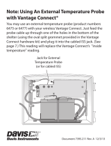
Included Components and Hardware
The Wireless Repeater comes with the components and hardware shown in the following
illustration. Some of the hardware might not be used, depending on how the repeater is
installed.
3-Volt Lithium
Battery
8" Cable Ties
1/4" x 1-1/2"
Lag Screws
Repeater in Shelter
with Solar Panel
U-Bolts
1/4" Flat Washers
1/4" Lock Washers
1/4" Hex Nuts

2
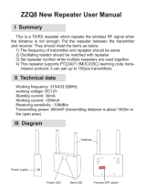
Repeater Board Contents
The board contained within the repeater enclosure has the following components:
Transmitter
DIP Switches
Repeater
DIP Switches
Repeater
Test Switch
TX
LED
Status
LED
1
2
3
4
56
78
Solar Power Input AC Adapter Socket
Battery Socket
First In Chain
Jumper

3
The components of the board are:
• Solar Power Input (used on #7627 models only) — Connects the solar panel on the
cover of the enclosure to the repeater board.
• AC Adapter Socket — Used to connect the optional 110 volt AC power adapter
(product number 6625) to the repeater board as an alternate source of power.
Note: Using the AC power adapter disables the solar-power charging circuit and makes the AC adapter the
main source of power.
• Battery Socket — Used to back up solar or AC power when the provided 3-volt
lithium battery is inserted.
• Transmitter DIP Switches — An eight-position switch used to set the transmitter IDs
the repeater listens to and repeats. The repeater comes with station ID 1 turned on and
all other transmitter IDs are turned off.
• Repeater DIP Switches —The first three positions in this four-position switch are
used to give the repeater a unique ID. All three positions are initially in the off
position, giving the repeater the ID of A.
Note: All station IDs are identified using numbers 1-8, and repeater IDs are identified using letters A-H so that
they are easily identifiable from each other.
• Repeater Test Switch — The fourth position in the four-position Repeater DIP switch
enables the TX and "STAT" LEDs to observe repeater and communication behavior.
Initially this switch is in the off position.
• First In Chain Jumper — A three-pin header
that can enable a repeater with a unique ID other
than A to become the first repeater in a chain if
two or more repeater chains are required in a
given network. See “First in Chain Applications”
on page 39 for more information.
Note: Any repeater with ID A or any repeater in a standard single-chain network should have the first in chain
jumper left in the default position (pictured above).
• "TX" LED — This green LED verifies transmission from the repeater to a receiver or
used in correlation with the "STAT" LED, displays error codes related to repeater
communication. See “Repeater Troubleshooting Error Codes” on page 34 for more
information.
• “STAT” (Status) LED — This multi-colored LED describes the status of the radio
packets received from stations or other repeaters or, used in correlation with the "TX"
LED, displays error codes related to repeater communication. See “Repeater
Troubleshooting Error Codes” on page 34 for more information.
Tools for Setup
The following tools and materials are required to set up and install the wireless repeater:
• Ratchet with 4'' (100 mm) or longer extension, 7/16'' (11 mm) size socket
• Paperclip
Default First In Chain
Jumper Position
(top two pins)

4
Wireless Repeater Introduction
The wireless repeater extends the range of a Davis Instruments weather station network
and can help overcome obstruction or interference problems present in a given network.
The transmission distance between a station and a receiver (known as radio-link range)
can be impaired by walls or other objects. When planning to use repeater(s) to lengthen
transmission distance from a station to a receiver keep the following information in mind:
• The typical radio-link range of all Vantage Pro2 stations and repeaters is:
• Line of sight: 1000' (300 m).
• Under most conditions (some visibility but small obstructions): 500 - 800' (150 -
250 m).
• Through Walls/Around Large Obstructions: 200 - 400' (60 - 120 m).
• The range for a standard wireless repeater has the same range limitations as all
Vantage Pro2 stations.
There are many things that can affect radio-link range and performance, and they should
also be considered when planning a network. They fall into two categories, obstructions,
and interference.
• Obstructions — These can include but are not limited to: walls, structures, rocks,
land, trees, foliage, any metal including mounting poles, fences, etc. For example,
your console or Envoy receiver will most likely be indoors. That means that there is
one or more walls between the receiver and the station(s) it is listening to. Depending
on the number and construction of these walls, the radio-link range can easily be
reduced to only a few hundred feet. While land (terrain) will completely block radio
signals, other items like trees and foliage will only reduce the radio-link range. Wet or
snow covered trees, foliage or walls will further reduce radio-link range.
• Interference — This can include: cordless phones, baby monitors, cell phones, cell
towers, ham radios, or any high-powered transmitter nearby. This can reduce the
range, because the radio can only receive what it can decipher over other
transmissions.
Antenna height can also affect radio-link range. Generally, the higher the better.
Mounting the radio/antenna as high as possible will not only get better radio-link range,
but it will be more likely to create a line-of-sight over some obstructions.
By placing repeaters between station transmitters and your receiver, you can increase the
range of your weather station network, keeping in mind the limitations discussed here.
You can go around obstructions, extend line-of-sight distances, or increase the signal
strength in noisy environments by placing radios closer together.
Note: Even longer line-of-sight distances can be achieved with the Long-Range Wireless Repeater, #7654.
See our website at www.davisnet.com for more about our Long-Range Wireless Repeater.

5
Wireless Repeater Installation Overview
The following is a overview of the steps involved for installing a repeater or series of
repeaters as part of your Vantage Pro2 wireless network:
• Determine the repeater/station configuration best suited to your wireless network.
• Apply power (battery or AC power).
• Verify communication with a station(s).
• Choose a location(s) for repeater(s).
• Test proposed location for signal strength.
• Configure the console or Envoy (and WeatherLink software, as needed) for repeater
identification.

6
Repeater Configuration/Architecture
Vantage Pro2 wireless repeaters are used to enhance the transmission range and
capabilities between a station, or multiple stations, and a receiver (console, Envoy, or
Vantage Connect). A repeater receives signals transmitted from a Vantage Pro2 station
and retransmits it to a console, wireless Weather Envoy, Envoy8X, Vantage Connect or
another repeater. Depending on transmission distance, one repeater or several repeaters
can be used to collect and retransmit weather data.
This section describes some of the repeater transmission situations and station networks
in which a repeater or set of repeaters can be used.
Repeater Architecture
Two repeater configurations are discussed in this section:
• Single Repeater Configuration — Any situation in which one repeater is needed to
transmit data from one station to one receiver (i.e., console or Envoy).
• Advanced Repeater Configuration — Any architecture where one or more stations
and/or one or more repeaters are combined to form a network of repeaters. For
example, if a station is placed further away from a console than the range of a single
repeater, multiple repeaters can be set up across the distance to transmit weather data
to the console in a chain. Another advanced repeater configuration might involve one
or more stations transmitting to a repeater. It is also possible to create a network using
a combination of multiple transmitters and repeaters.
Note: All range estimates used in the examples below are based on the idea that the distance between a
station and a repeater is a “radio-link”. See “Wireless Repeater Introduction” on page 4 for more
information about the real-world range of a radio-link.

7
Single Repeater Configuration
Use a single repeater as part of a single station/single receiver setup when the distance is
so great that a station alone can not successfully communicate with a receiver. The
distance is greater than one radio-link but less than three.
The diagram below shows the typical single repeater configuration, with each arrow
representing a radio-link.
This configuration permits greater distances between a station and a receiver.
Note: If the distance between a station and a receiver is more than two radio-links, see “Multiple Repeater
(Daisy-Chain) Configuration” below. If more than one station exists, see “Multiple Stations/One Repeater
Configuration” on page 8.
Advanced Repeater Configurations
Multiple Repeater (Daisy-Chain) Configuration
If the distance between a station and receiver is greater than the single repeater
configuration distance can provide range for, or if the station, repeater and receiver are
not in line of sight of each other, more than one repeater should be used to transmit
weather data. A multiple repeater daisy-chain configuration has the capability to transmit
up to nine radio-links between the station and a receiver, but should be limited to four
repeaters (five radio-links).
Note: Although the maximum of eight repeaters is based on the number of unique repeater IDs (A-H) available
in a network, the limit of four repeaters in a daisy chain is based on communication/timing issues.
Any Vantage Pro2
Transmitting Station
1
1
1
1
1
Vantage Pro2 or Vantage Vue Console
Weather Envoy, Envoy8X, or Vantage Connect
A
A
A
1
A
AND/OR
Repeater
A
™
N
S
WE
NE
SE
NW
SW
WIND
am
INSIDE OUTSIDE
RAIN RATE
CHILL
in/hr
FF
F
in
Vantage VUE
TEMPERATURE
HUMIDITY
BAROMETRIC
PRESSURE
RAINFALL
WEATHER
CENTER

8
The above diagram displays an example daisy-chain configuration of one station and
three repeaters, creating a total line of sight transmission distance of four radio-links.
This configuration allows more flexibility between a station and a console, especially
around obstructions or interference.
Multiple Stations/One Repeater Configuration
One repeater can be used to transmit weather information from multiple stations to a
receiver if the repeater is within a radio-link radius of each station. The repeater can
receive and repeat weather data from up to eight different weather stations.
Note: The limit of eight stations is based on the number of unique transmitter IDs (1-8) available in a network.
1 1
1
11
1
1
A
B
C
C
Repeater Repeater
Repeater
Vantage Vue or
Vantage Pro2
Console
Any Vantage Vue
or Vantage Pro2
Transmitting Station
N
S
WE
NE
SE
NW
SW
WIND
am
INSIDE OUTSIDE
RAIN RATE
CHILL
in/hr
FF
F
in
Vantage VUE
TEMPERATURE
HUMIDITY
BAROMETRIC
PRESSURE
RAINFALL
WEATHER
CENTER
A
B
C
Temp/Humidity
Station
or
Temperature
Station
Leaf & Soil Moisture
Station
or
Anemometer
Transmitter Kit
Vantage Pro2
Station
Repeater
1
2
3
2
1
3
A
2
1
3
2
1
3
Vantage Pro2
Console/Receiver
A
A

9
The diagram on the previous page shows a multiple transmitter configuration of three
stations and one repeater, with the repeater within a radio-link of all three stations and the
receiver, extending the distance between the repeater and the three stations.
The repeater can receive signals from up to eight stations/transmitters of any type.
However, there are some limitations as to how many and what type of transmitters the
receiver can listen to.
The table below lists the maximum number of stations allowable for a receiver:
Maximum Number of Transmitters in a Network
*Replaces the ISS anemometer.
**Two are allowable only if both stations are only partially populated. For example, A network can either
have both a Leaf Wetness/Temperature station and a Soil Moisture/Temperature station, or it can have
one combined Leaf Wetness and Soil Moisture/Temperature station.
Combination Network Configurations
Given the flexibility of the repeater to listen to more than one station and to transmit to
other repeaters, both stations and repeaters can be set up to create a variety of transmitter
networks to transmit to one receiver. Up to four repeaters and eight stations can be
configured to transmit to one receiver in a variety of ways.
The above diagram displays a multiple transmitter/repeater configuration with five
stations and three repeaters, with each repeater listening to a station or multiple station
Station Type
Maximum
Number
Integrated Sensor Suite (ISS) 1
Anemometer Transmitter Kit* 1
Leaf & Soil Moisture/Temperature
Station
2**
Temperature Station 8
Temperature/Humidity Station 8
Temp/Humidity
Station
Leaf & Soil Moisture
Station
Vantage Pro2
Station
RepeaterRepeater
2
4 4
4
5
C
3
3
B
Repeater
1
1
2
A
2
1
4
5
3
4
3
2
1
5
Vantage Pro2
Console/Receiver
Temperature
Station
Anemometer
Transmitter Kit
2
1
2
3
1
A
B C
C

10
also to the previous repeater. Each repeater and station must be within a radio-link of
another repeater or receiver.
See “Maximum Number of Transmitters in a Network” on page 9 for the receiver
limitations.
There is also a maximum of four repeaters allowable in a network.
Note: Although one repeater can listen to multiple transmitters at a time, it can only listen to one other
repeater. The repeaters have to be in alphabetic order, with A being first. Each repeater after repeater A
looks for the repeater with the previous ID and any transmitter IDs it has been assigned.
Implementing a Configuration
Now that you understand the possible repeater configurations, sketch or map out your
proposed weather network. Tools to assist you include:
• Maps — paper or electronic, purchased or online, regular, topographic and/or satellite
imagery.
• Measuring devices — tape measures, string, range finders (optical or laser), handheld
GPS receiver, etc.
Start by showing the placement of the stations and the location of the receiver(s) in your
network. Note any obstructions or potential interference sources. Also note that the
repeater might be limited by height. Using one type or a combination of network types
described previously, plan your repeater placement to get around any obstructions, cover
the required distances, and assure adequate signal strength between radio-links for your
anticipated conditions.
Once a configuration has been chosen that best suits the needs of the desired station/
receiver setup, installing and verifying communication between the station(s) and
repeater(s) is the next step. Set up and test your network configuration as described in the
next sections before installing in the field.See the section for the installation process best
suited to the configuration type chosen:
• See page 12 for a single repeater installation.
• See page 18 for a “daisy-chain” installation.
• See page 21 for a multiple station/single repeater installation.
• See page 24 for a combination network installation.
Note: Many of the basic steps for installing and configuring your repeater network are discussed in detail as
part of the single repeater installation. Please review “Single Repeater Installation” on page 12 even if
you are installing an advanced network of repeaters.

11
Applying Power
Applying Battery Power
1. To view the wireless repeater board,
open the shelter enclosing the wireless
repeater.
2. Insert the 3-volt lithium battery into
the battery socket at the top of the
board. Be sure to match the “+” sign
on the battery with “+” sign displayed
in the battery socket.
Once the battery is installed, it begins
powering the board.
You may hear a high pitched sound as
the repeater charges up.
Once charged, the repeater performs
the Power-On Self Test (POST) using
the two LEDs located at the bottom of
the board. The "STAT" LED blinks
red, yellow and then green, followed
by the "TX" LED blinking green once,
indicating that the repeater is powered
up and has passed POST.
Note: On battery power alone, it can take up to two or three minutes for the board to charge before the
repeater begins POST and the LED lights blink their pattern. With sufficient solar power, the repeater
powers up and is ready to communicate immediately.
Once the POST light sequence displays, the repeater is ready to communicate. If the
repeater does not display the POST light pattern within three minutes, see “Maintenance
and Troubleshooting” on page 34 for more information.
3-Volt Lithium
Battery

12
Single Repeater Installation
A single repeater installation is used in situations where one transmitting station can not
successfully communicate with a receiver, or if a station needs to be farther away from a
receiver than maximum line-of-sight radio link distance. The repeater can also be used as
a signal amplifier for situations in which a signal is weak between a transmitting station
and a receiver.
Verify Transmitter ID
The wireless repeater listens to and communicates with a station transmitter by looking
for that station’s unique transmitter ID. Each wireless station, including the Integrated
Sensor Suite (ISS), uses one of eight selectable transmitter IDs. The station’s transmitter
board, known as a Sensor Interface Module (SIM) contains a four-position DIP switch
used to select the station’s transmitter ID.
There are two ways to find out the transmitter ID the station is currently transmitting on:
• Check the DIP switch positions on a station.
• Check the console for stations currently being received.
Checking DIP Switch Positions on a Station
The Transmitter DIP switch is used to give the station a unique ID. DIP switches #1, 2
and 3 on the transmitter DIP switch control the ID the station uses to transmit on. DIP
switch #4 is used for transmission testing, not for programming the transmitter ID. See
the manual for your Vantage Pro2 Integrated Sensor Suite or transmitting station to locate
the Transmitter ID DIP switch.
To find the transmitter ID on your station:
1. Find the white box housing the SIM for your station, open it and locate
the four-position DIP switch, usually located in the upper right-hand
corner of a station’s board.
The default transmitter ID for all stations is 1 and the default position for all of the DIP
switches is down or OFF.
Use this table to determine which transmitter ID the station is using based on the
positions of the #1, 2, and 3 switches on the DIP switch.
ID CODE SWITCH 1SWITCH 2SWITCH 3
1 (default) off off off
2 off off ON
3 off ON off
4 off ON ON
5 ON off off
6 ON off ON
7 ON ON off
8 ONONON
1234
ON

13
2. Use the “Transmitter and Repeater ID Worksheet” located inside the cover of this
manual to record the transmitter ID used.
Optional: Changing Transmitter ID
If there is any reason that the transmitter ID needs to be set to another channel, the DIP
switch should be set now to the desired ID.
To change to another ID:
1. Use a paper clip to turn DIP switch positions #1, 2, and 3 on and off as desired using
the Transmitter ID Table (on the previous page) to change the station to the desired
transmitter ID.
The transmitter ID can be changed if any of the following issues are true:
• Another Davis Instruments wireless weather station operating nearby already uses
transmitter ID 1.
Note: Keep in mind that the repeater comes preset to listen for transmitter ID 1. If you have only one station, it
is recommended that you keep the station on ID 1.
• Additional wireless transmitting stations have been purchased and one of the
stations has been designated as Station ID 1 instead of the selected ISS.
Viewing Stations Transmitting to the Console
If the station is too far away or in an inconvenient location, making it hard to view the
transmitter ID from the station, the console can be used to determine the transmitter ID.
To find the transmitter ID using the console:
1. Place the console in an area where it is likely to receive the transmitter signal.
2. Press the DONE and down arrow (-) keys at the same time.
• Vantage Pro2: The first screen in the Setup Mode is displayed (“Receiving From...”
will appear). This screen locates and eventually displays the active transmitter IDs
the console is receiving. See the Vantage Pro2 Console User Guide for more
information about Setup Mode and the first screen.
• Vantage Vue: Press the DONE key until the Active Transmitters screen is displayed
(“Receiving From...” will appear). See the Vantage Vue Console User Guide for
more information about Setup Mode and the Active Transmitters screen.
3. Use the “Transmitter and Repeater ID Worksheet” located inside the front cover, to
record the transmitter ID used.
4. Return to the Current Weather Mode by pressing and holding down DONE.
Note: It may take several minutes for the console to discover and display all transmitter IDs. This screen will
only display stations the console can hear successfully. Even if a transmitter ID has been successfully
configured, the console does not receive the signal unless it is in range.

14
Verifying Repeater ID
The wireless repeater also contains a DIP switch used to give the repeater a unique
identification in the way each station’s Transmitter DIP switch gives the station a unique
ID. To avoid confusion, repeaters use alphabetic identification A through H.
Note: For single repeater installations, the repeater should remain on the default ID A. If the repeater is given
an ID other than A, it will keep looking for a repeater with a letter previous to its ID. For example, if the
repeater is given ID C, it will look for repeater B, whether or not the installation has a repeater B.
Verify that the repeater DIP switches are all in the OFF position.
In the example on the next page, the repeater has an ID of A and communication testing
can continue as planned. If any of the three switches are on in any other combination,
switch them off. Refer to the table marked “Repeater ID DIP Switch Positions” on
page 18 for more information.
Verifying Reception from Repeater
Once the transmitter ID has been verified or changed for use with the wireless repeater, it
is time to program the wireless repeater with the station ID information. To do this:
1. Place the repeater in an area where it is likely to receive the transmitter signal.
2. Open the wireless repeater enclosure and locate the four-position Repeater DIP
switches next to the eight-position Transmitter DIP switch at the bottom of the
repeater board.
3. Set the #4 test DIP Switch of the repeater to ON. The test switch enables the TX and
"STAT" LEDs. They display light patterns based on the behavior of the wireless
repeater and how it is receiving signals from the transmitter.
Any Vantage Pro2
Station: ID #1
Repeater
1
1
1
Vantage Pro2 or
Vantage Vue
Console
A
A
Transmitter DIP
Switch with ID 1 ON
Repeater DIP
Switch set to ID A
ON
A
N
S
WE
NE
SE
NW
SW
WIND
am
INSIDE OUTSIDE
RAIN RATE
CHILL
in/hr
FF
F
in
Vantage VUE
TEMPERATURE
HUMIDITY
BAROMETRIC
PRESSURE
RAINFALL
WEATHER
CENTER

15
The "STAT" LED flashes red when it detects a radio
signal. The "STAT" LED flashes green when a good
packet has been received. The "TX" LED blinks when the
packet has been repeated to a receiver.
4. Turn the desired transmitter ID DIP to ON and make sure
all the other transmitter IDs are in the OFF position.
Note: If the station already has a transmitter ID of 1, you don’t need to change any of the Transmitter ID DIP
Switches.
Note: See “Maintenance and Troubleshooting” on page 34 if the above LED pattern does not display.
5. Important: Turn the #4 test DIP Switch to OFF once the test is complete, otherwise it
will significantly shorten battery life.
6. Close the repeater enclosure.
Verifying Repeater Communication with a Console
Once the repeater successfully recognizes a transmitter, the console should be set up to
receive the transmitter data through the repeater.
On the Vantage Pro 2 console:
1. Press DONE and the down arrow (-) to enter Setup Mode.
2. Screen 1 lists active transmitters.
This screen displays only the
active transmitter IDs the console
is receiving. Wireless repeater
identification is not displayed on
this screen.
The transmitter ID for the station set on the
repeater should display on this screen, with the number displaying above the ticker tape and an “X” flashing on
the bottom right of the console screen.
Note: It may take several minutes for the console to acquire repeated station. If the transmitter ID does not
display in this screen after 10 minutes, see “Maintenance and Troubleshooting” on page 34.
3. Press DONE to display Screen 2: Configuring Transmitter IDs.
4. Select the transmitter ID transmitting through the repeater using the right (>) and left
(<) arrows. If the required ID is not on, turn it on now by pressing the up (+) arrow
until “ON” displays on the screen. Change the station type by pressing GRAPH until
the correct station type displays.
5. Press 2ND and then press WIND to enter Repeater Setup Mode and to select or
deselect a repeater ID. Once the console is in the Repeater Setup Mode, subsequent
pressing of WIND continue to cycle through the all the repeater IDs.
6. Press WIND repeatedly to cycle to the desired repeater ID or to turn off the repeater
ID in the lower right hand corner. When no repeater ID is shown, the console is
configured to listen directly to a station and not to a repeater.
Note: If a transmitter ID is turned off, pressing WIND or 2ND and WIND will not display the repeater ID.
TX
STAT
S
TATI
O
N N
O
.1
4
STATION NO.1

16
This illustration (right) shows the
console set up to receive an ISS
station on transmitter ID 1 from
repeater A.
7. Press DONE to continue to the
other screens in the Setup Mode, or
press and hold DONE to return to the Current Weather Mode.
Note: See the Vantage Pro 2 Console User Guide for more information on the other screens in Setup Mode if
necessary.
On the Vantage Vue console:
1. Press DONE and the down arrow
(-) to enter Setup Mode. Press
DONE repeatedly until the Active
Transmitters screen (“Receiving
From...” appears).
The transmitter ID for the station
set on the repeater should display on this screen, with “transmitting waves” flashing
on the tower symbol icon above the graph area.
Note: It may take several minutes for the console to acquire repeated station. If the transmitter ID does not
display in this screen after 10 minutes, see “Maintenance and Troubleshooting” on page 34.
2. Press DONE again to display
Screen 6: Configuring Transmitter
IDs. Press 2ND and WIND to turn
the repeater function on and to
select a Repeater ID. The first
Repeater ID is Repeater A.
3. Press WIND repeatedly to cycle to the desired repeater ID or to clear the repeater ID
in the right hand corner. When no repeater ID is shown, the console is configured to
listen directly to a station and not to a repeater.
Note: If a transmitter ID is turned off, pressing WIND or 2ND and WIND will not display the repeater ID.
4. Press DONE to continue to the other screens in the Setup Mode, or press and hold
DONE to return to the Current Weather Mode.
Note: See the Vantage Vue Console User Guide for more information on the other screens in Setup Mode if
necessary.
To verify that setup was successful, in the console’s Current Weather Mode:
View the transmitter information displaying at the bottom of the console screen.
If the ISS’s transmitter ID being repeated is displayed and an “X” flashes in the
bottom right-hand corner of the ticker tape (Vantage Pro2), or the “transmitting
waves” flash on the tower icon above the graph area (Vantage Vue), the ISS is being
repeated and received by the console successfully.
The repeater’s information also displays in the diagnostics screens.
1
/