Toro 206cc OHV Vacuum Blower User manual

Category
Air blowers/dryers
Type
User manual

Toro 206cc OHV Vacuum Blower is a versatile machine that combines vacuum and blower functions, making it ideal for yard cleanup tasks. With its powerful 206cc OHV engine, it delivers exceptional performance in both vacuuming and blowing modes. The blower tube and debris bag allow for efficient collection and disposal of leaves, grass clippings, and other debris. The adjustable intake housing height and the ability to convert from vacuum to blower mode provide added convenience and flexibility.

Toro 206cc OHV Vacuum Blower is a versatile machine that combines vacuum and blower functions, making it ideal for yard cleanup tasks. With its powerful 206cc OHV engine, it delivers exceptional performance in both vacuuming and blowing modes. The blower tube and debris bag allow for efficient collection and disposal of leaves, grass clippings, and other debris. The adjustable intake housing height and the ability to convert from vacuum to blower mode provide added convenience and flexibility.

Form No. 3352-284 Rev B
206cc OHV Vacuum Blower
Model No. 62925 —Serial No. 250000001 and Up
Register your product at www.Toro.com Original Instructions (EN)
T his spark ignition system complies with Canadian
ICES-002
T he enclosed Engine Owner’ s Man ual is
supplied f or inf or mation r egarding the US
En vir onmental Pr otection Agency (EP A) and
the Calif or nia Emission Contr ol R egulation of
emission systems, maintenance, and w ar ranty .
R eplacements may be order ed thr ough the
engine man uf actur er .
Introduction
R ead this infor mation carefully to lear n ho w to
operate and maintain y our product properly and
to a v oid injur y and product damag e . Y ou are
responsible for operating the product properly
and safely .
Y ou ma y contact T oro directly at www .T oro .com
for product and accessor y infor mation, help
finding a dealer , or to register y our product.
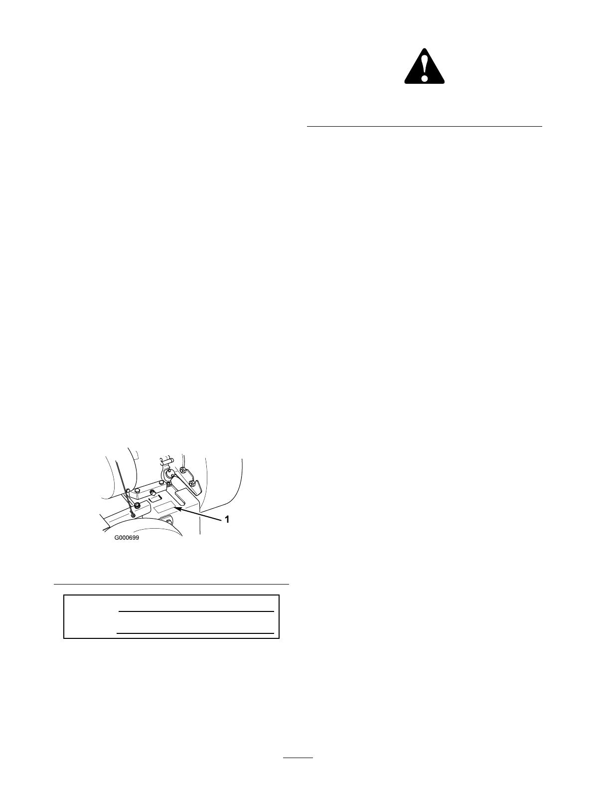
W henev er y ou need ser vice , g en uine T oro par ts ,
or additional infor mation, contact an A uthorized
Ser vice Dealer or T oro Customer Ser vice and ha v e
the model and serial n umbers of y our product
ready . Figure 1 identifies the location of the model
and serial n umbers on the product. W rite the
n umbers in the space pro vided.
Figure 1
1. Location of the model and serial numbers
Model No.
Serial No.
T his man ual identifies potential hazards and has
safety messag es identified b y the safety aler t
symbol ( Figure 2 ), whic h signals a hazard that ma y
cause serious injur y or death if y ou do not follo w
the recommended precautions .
Figure 2
1. Safety alert symbol.
T his man ual uses tw o other w ords to highlight
infor mation. Impor tant calls attention to special
mec hanical infor mation and Note emphasizes
g eneral infor mation w or th y of special attention.
Contents
Introduction . . . . . . . . . . . . . . . . . . . . . . . . . . . . . . . . . . . . . . . . . . . . . . . . . . . . . . . 2
Safety . . . . . . . . . . . . . . . . . . . . . . . . . . . . . . . . . . . . . . . . . . . . . . . . . . . . . . . . . . . . . . . . . . 4
General Safety . . . . . . . . . . . . . . . . . . . . . . . . . . . . . . . . . . . . . 4
Safety and Instr uctional Decals . . . . . . . . . . . . 6
Setup . . . . . . . . . . . . . . . . . . . . . . . . . . . . . . . . . . . . . . . . . . . . . . . . . . . . . . . . . . . . . . . . . . 7
1 Installing the Upper Handle and
Controls . . . . . . . . . . . . . . . . . . . . . . . . . . . . . . 7
2 Installing the Disc harg e Chute
and Bag . . . . . . . . . . . . . . . . . . . . . . . . . . . . . . . 8
3 Installing the Snout . . . . . . . . . . . . . . . . . . . . . . . . . . . 9
Product Ov er view . . . . . . . . . . . . . . . . . . . . . . . . . . . . . . . . . . . . . . . . . . . . . 10
Controls . . . . . . . . . . . . . . . . . . . . . . . . . . . . . . . . . . . . . . . . . . . 10
Operation . . . . . . . . . . . . . . . . . . . . . . . . . . . . . . . . . . . . . . . . . . . . . . . . . . . . . . . . . . 12
Adding Fuel . . . . . . . . . . . . . . . . . . . . . . . . . . . . . . . . . . . . . . 12
Chec king the Oil Lev el . . . . . . . . . . . . . . . . . . . . . . . 13
Star ting and Stopping the
Engine . . . . . . . . . . . . . . . . . . . . . . . . . . . . . . 14
Adjusting the Intak e Housing
Height . . . . . . . . . . . . . . . . . . . . . . . . . . . . . . . 14
Dri ving the Mac hine F orw ard . . . . . . . . . . . . 15
Using the Debris Bag . . . . . . . . . . . . . . . . . . . . . . . . . 15
Con v er ting from V acuum to
Blo w er . . . . . . . . . . . . . . . . . . . . . . . . . . . . . . . 15
Maintenance . . . . . . . . . . . . . . . . . . . . . . . . . . . . . . . . . . . . . . . . . . . . . . . . . . . . . . 18
R ecommended Maintenance
Sc hedule(s) . . . . . . . . . . . . . . . . . . . . . . . . . . . . . . . 18
Premaintenance Procedures . . . . . . . . . . . . . . . . . . . . . . . 18
Lubrication . . . . . . . . . . . . . . . . . . . . . . . . . . . . . . . . . . . . . . . . . . . . . . . . 18
Oiling the Caster W heels and Pi v ot
P oints . . . . . . . . . . . . . . . . . . . . . . . . . . . . . . . . 18
Greasing the R ear Idler
Assembly . . . . . . . . . . . . . . . . . . . . . . . . . . 19
Engine Maintenance . . . . . . . . . . . . . . . . . . . . . . . . . . . . . . . . . . 19
Changing the Oil . . . . . . . . . . . . . . . . . . . . . . . . . . . . . . . 19
Ser vicing the Air Cleaner . . . . . . . . . . . . . . . . . . . 19
Ser vicing the Spark Plug . . . . . . . . . . . . . . . . . . . . 20
Fuel System Maintenance . . . . . . . . . . . . . . . . . . . . . . . . . . 21
© 2006—The Toro® Company
8111 Lyndale Avenue South
Bloomington, MN 55420
2
Contact us at www.Toro.com.
Printed in the USA.
All Rights Reserved
Emptying the Fuel T ank . . . . . . . . . . . . . . . . . . . . . 21
Dri v e System Maintenance . . . . . . . . . . . . . . . . . . . . . . . . . 21
Adjusting the T raction Dri v e . . . . . . . . . . . . . . 21
Belt Maintenance . . . . . . . . . . . . . . . . . . . . . . . . . . . . . . . . . . . . . . . 22
Adjusting the Dri v e Belt . . . . . . . . . . . . . . . . . . . . . 22
R e placing the Dri v e Belt . . . . . . . . . . . . . . . . . . . . 22
Storag e . . . . . . . . . . . . . . . . . . . . . . . . . . . . . . . . . . . . . . . . . . . . . . . . . . . . . . . . . . . . . . 24
R emo ving the Mac hine from
Storag e . . . . . . . . . . . . . . . . . . . . . . . . . . . . . . 24
3
Safety
T o ensure maxim um safety and best perfor mance ,
and to g ain kno wledg e of the product, it is essential
that y ou and any other operator of the mac hine
read and understand the contents of this man ual
before the engine is ev er star ted.
T his is the safety aler t symbol. It is used to aler t
y ou to potential personal injur y hazards . Obey all
safety messag es that follo w this symbol to a v oid
possible injur y or death.
Improperly using or maintaining this mac hine
could result in injur y or death. T o reduce this
potential, comply with the follo wing safety
instr uctions .
Engine exhaust contains carbon mono xide,
an odor less, deadl y poison that can kill y ou.
Do not r un the engine indoor s or in an
enclosed ar ea.
General Safety
Training
R ead this operator’ s man ual carefully . Be
thoroughly familiar with the controls and the
proper use of the mac hine before star ting it.
Nev er allo w c hildren to operate the mac hine .
Local regulations ma y restrict the ag e of the
operator .
Nev er allo w adults unfamiliar with these
instr uctions to operate the mac hine .
Nev er use the mac hine while people (especially
c hildren) or pets are nearb y . Stop the mac hine
if any one enters the area.
T ragic accidents can occur if the operator is
not aler t to the presence of c hildren. Children
are often attracted to the mac hine . Nev er
assume that c hildren will remain where y ou
last sa w them.
K ee p c hildren out of the w ork area and under
the w atc hful care of a responsible adult.
Be aler t and tur n the mac hine off if c hildren
enter the area.
Use extra care when approac hing blind cor ners ,
shr ubs , trees , or other objects that ma y obscure
vision.
K ee p in mind that the operator or user is
responsible for accidents or hazards occur ring
to other people or their proper ty .
See the man ufacturer’ s instr uctions for proper
operation and installation of accessories . Use
only the accessories that are appro v ed b y the
man ufacturer .
Preparation
W hile operating, alw a ys w ear substantial
footw ear and long trousers .
Do not operate the mac hine when barefoot or
w earing open sandals .
Alw a ys w ear safety g og gles or safety glasses
with side shields when operating the mac hine .
W ar ning: Gasoline is highly flammable . T ak e
the follo wing precautions:
Store fuel in containers specifically designed
for this pur pose .
R efuel outdoors only and do not smok e
while refuelling .
Add fuel before star ting the engine . Nev er
remo v e the cap of the fuel tank or add
g asoline while the engine is r unning or
when the engine is hot.
If g asoline is spilled, do not attempt to star t
the engine . Mo v e the mac hine a w a y from
the area of spillag e to a v oid creating any
source of ignition until the g asoline v apors
ha v e dissipated.
R e place all fuel tank and container caps
securely .
If y ou m ust drain the fuel from the fuel
tank, do it outdoors .
R e place faulty m ufflers .
Before using, alw a ys visually inspect the
mac hine for w ear or damag e . R e place w or n
or damag ed par ts .
Operation
Do not operate the engine in a confined space
where dang erous carbon mono xide fumes can
collect.
Operate only in da ylight or in g ood ar tificial
light.
4
Alw a ys be sure of y our footing on slopes .
W alk; nev er r un.
K ee p a fir m hold on the handle .
Ex ercise caution when c hanging the direction
on slopes .
Do not operate on stee p slopes .
Nev er operate the mac hine with damag ed or
missing guards or shields , or without safety
devices (suc h as blo w er tube or debris bag) in
place .
Diseng ag e the traction dri v e lev er before
star ting the engine .
Do not put y our hands or feet near or under
the snout. K ee p clear of the the snout and
blo w er tube (when installed) at all times .
Stop the engine and disconnect the spark-plug
wire:
before clearing bloc kag es
before c hec king, cleaning, or w orking on
the mac hine
before c hanging from v acuum to blo w er
or blo w er to v acuum
Stop the engine:
whenev er y ou lea v e the mac hine
before refuelling
Shut the engine off and w ait until the impeller
comes to a complete stop before remo ving the
debris bag .
Do not operate the mac hine while under the
influence of alcohol or dr ugs .
If the mac hine should star t to vibrate
abnor mally , stop the engine and c hec k
immediately for the cause . Vibration is
g enerally a w ar ning of trouble .
Do not operate near drop-offs , ditc hes , or
embankments . Y ou could lose y our footing or
balance .
Do not operate on w et g rass . R educed footing
could cause slipping .
Maintenance and Storage
K ee p all n uts , bolts , and screws tight to ensure
that the mac hine is in safe w orking condition.
Nev er store the mac hine with g asoline in the
tank inside a building where fumes ma y reac h
an open flame or spark.
Allo w the engine to cool before storing the
mac hine in any enclosure .
T o reduce the fire hazard, k ee p the engine ,
m uffler , and g asoline storag e area free of g rass ,
lea v es , or ex cessi v e g rease .
Chec k the debris bag frequently for w ear or
deterioration.
R e place w or n or damag ed par ts .
Use extra care when handling g asoline; g asoline
v apors are explosi v e .
K ee p the mac hine free of g rass , lea v es , or
other debris buildup . Clean up any oil or fuel
that spills .
Stop and inspect the mac hine if y ou strik e an
object. R e pair the mac hine , if necessar y , before
star ting the engine .
Debris bag components are subject to w ear ,
damag e , and deterioration, whic h could expose
mo ving par ts or allo w objects to be thro wn.
F requently c hec k the components and re place
them with the man ufacturer’ s recommended
par ts when necessar y .
Do not c hang e the speed settings on the
engine .
If y ou m ust drain the fuel from the fuel tank,
do it outdoors .
T o ensure the best perfor mance and safety ,
purc hase only g en uine T oro re placement par ts
and accessories .
Maintain or re place safety and instr uction
decals when necessar y .
Sound Pressure Level
T his unit has an equi v alent contin uous A-w eighted
sound pressure at the operator ear of 97 dB(A),
based on measurements of identical mac hines per
procedures described in EN 11201.
Sound Power Level
T his unit has a sound po w er lev el of 107 dB(A),
based on measurements of identical mac hines per
procedures described in EN 11094.
Vibration Level
T his unit has a maxim um hand-ar m vibration lev el
of 6.4 m/s2, based on measurements of identical
mac hines per procedures described in EN 1033.
5
Safety and Instructional Decals
Safety decals and instr uctions are easily visible to the operator and are located near any
area of potential dang er . R e place any decal that is damag ed or lost.
105-4062
1. Warning—read the Operator’s Manual .
3. Warning—stop the engine, remove the wire from the spark
plug, and read the instructions before servicing or performing
maintenance.
2. Thrown object hazard—stay a safe distance from the machine. 4. Cutting/dismemberment hazard, impeller—stay away from
moving parts.
93-4137
1. Low.
3. High
2. Height of vacuum snout
93-4139
1. Thrown object
hazard—stay a safe distance
from the machine.
3. Cutting/dismemberment
hazard, impeller—stay
away from moving parts.
2. Warning—stop the engine
and read the instructions
before servicing or
performing maintenance.
93-4141
1. To engage the traction drive, move the traction drive lever
to the handle.
6
Setup
Loose Parts
Use the chart below to verify that all parts have been shipped.
Step
Description
Qty.
Use
Upper handle assembly
1
Bag support 1
Bolt (5/16 x 1-1/2 inches)
4
Locknut (5/16 inch)
4
Bolt (10-32)
1
Locknut (10-32)
1
Rope guide
1
Bolt (1/4 x 3/4 inch)
1
Locknut (1/4 inch)
1
Height control rod
1
1
Hair pin cotter
2
Install the upper handle and
controls.
Bolt (1/4 x 1/2 inch)
1
Lock washer (1/4 inch)
1
2
Debris bag
1
Install the discharge chute.
Blower tube
1
Blower intake screen
1
3
Locknut
3
Install the snout.
Step
1
Installing the Upper Handle
and Controls
Parts needed for this step:
1
Upper handle assembly
1 Bag support
4
Bolt (5/16 x 1-1/2 inches)
4
Locknut (5/16 inch)
1
Bolt (10-32)
1
Locknut (10-32)
1
Rope guide
1
Bolt (1/4 x 3/4 inch)
1
Locknut (1/4 inch)
1
Height control rod
2
Hair pin cotter
Procedure
1. Attac h the upper handle to the lo w er handle
with 4 bolts (5/16 x 1-1/2 inc hes) and loc kn uts
(5/16 inc h) ( Figure 3 ).
Figure 3
1. Lower handle
3. Bag support
2. Upper handle 4. Rope guide
2. Secure the bag suppor t to the inside of the
lo w er handle while mounting the handle
( Figure 3 ).
3. Secure star ter rope guide to the lo w er handle
with a bolt (1/4 x 1-3/4 inc hes) and loc kn ut
(1/4 inc h) ( Figure 4 ).
7
Figure 4
1. Bolt (1/4 x 1-3/4 inches)
3. Pull rope through rope
guide
2. Locknut (1/4 inch)
4. Pull the star ter rope through the guide
( Figure 4 ).
5. Hook the lo w er end (ball end) of the traction
control wire in the k eyhole slot in the ar m on
the traction dri v e guard ( Figure 5 ).
Figure 5
1. Traction control wire
3. Bolt and nut (10–32)
2. Traction drive guard
6. Secure the ball in the k eyhole slot with a bolt
(10-32) and n ut (10-32) ( Figure 5 ).
Note: Mak e sure ball end of cable is not
betw een screw head and dri v e guard.
7. Secure the lo w er end of the height control rod
to the brac k et on the front wheel suppor t with
a hair pin cotter ( Figure 6 ).
Figure 6
1. Height control rod
3. Hairpin cotter
2. Front wheel support
bracket
8. Secure the upper end of the height control rod
to the height adjustment handle with a hair pin
cotter ( Figure 7 ).
Figure 7
1. Height control rod
3. Hairpin cotter
2. Height adjustment handle
Step
2
Installing the Discharge
Chute and Bag
Parts needed for this step:
1
Bolt (1/4 x 1/2 inch)
1
Lock washer (1/4 inch)
1
Debris bag
Procedure
1. Install the disc harg e c hute and secure it with
a bolt (1/4 x 1/2 inc h) and loc k w asher (1/4
inc h) ( Figure 8 ).
8
Figure 8
1. Chute
2. Bolt (1/4 inch) and lock
washer
2. P osition the bag onto the handle , hooking the
g rommets o v er the pins and the bag strap o v er
the handle ( Figure 9 ).
Figure 9
1. Grommets
2. Elasticized neck
3. Slip the elasticized nec k of the bag o v er the
flang es on the c hute ( Figure 9 ).
Step
3
Installing the Snout
Parts needed for this step:
1
Blower tube
1
Blower intake screen
3
Locknut
Procedure
1. Mount the lo w er edg e of the snout flang e into
the mounting brac k et ( Figure 10 ).
Figure 10
1. Vacuum snout
3. Retainer ange
2. Lower edge of ange 4. Locknut
2. P osition the retainer flang e o v er the 3 bolt ends
protr uding through the snout ( Figure 10 ).
3. Secure the snout and flang e to the blo w er with
3 w ashers and loc kn uts ( Figure 10 ).
9
Product Overview
Figure 11
1. Engine
4. Handle
2. Vacuum snout
5. Traction control lever
3. Height adjustment control 6. Debris bag
Controls
Height Adjustment Control
Y ou can adjust the clearance betw een the air
intak e housing and the g round b y mo ving height
adjustment control ( Figure 12 ) to desired position.
Set the height to lo w (L) for v acuuming hard
surfaces suc h as sidew alks or dri v ew a ys and to
high (H) for thic k lush turf with a hea vy co v ering
of lea v es or clippings . T he v acuum will w ork best
when y ou k ee p the intak e as close to the g round as
is practical for the task y ou are perfor ming .
Figure 12
1. Height adjustment control
Traction Control Lever
Hold the traction control lev er ( Figure 13 ) ag ainst
the handle to mo v e forw ard. R elease the traction
control lev er to stop forw ard motion.
Figure 13
1. Traction control lever (disengaged)
Choke and Throttle Levers
R efer to Star ting and Stopping the Engine in
Operation , pag e 12 for detailed instr uctions on
using these controls .
10
Figure 14
1. Choke lever 4. Choke position
2. Throttle lever 5. Slow position
3. Run position 6. Fast position
11
Operation
Before operating, c hec k the fuel and oil lev el, and
remo v e debris from the mac hine . Also , ensure that
the area is clear of people and debris .
Adding Fuel
In cer tain conditions, gasoline is extr emel y
flamma ble and highl y explosi v e. A fir e or
explosion fr om gasoline can bur n y ou and
other s and can dama ge pr oper ty .
Fill the fuel tank outdoor s, in an open
ar ea, when the engine is cold. W ipe up
an y gasoline that spills.
Do not fill the fuel tank completel y full.
Add gasoline to the fuel tank until the
lev el is 1/4 to 1/2 inch (6 to 13 mm)
belo w the bottom of the filler neck. T his
empty space in the tank allo ws gasoline
to expand.
Nev er smok e when handling gasoline,
and stay a w ay fr om an open flame or
wher e gasoline fumes may be ignited by
a spar k.
Stor e gasoline in an appr o v ed container
and k eep it out of the r each of childr en.
Nev er buy mor e than a 30-day suppl y of
gasoline.
Al w ays place gasoline container s on the
g r ound a w ay fr om y our v ehicle bef or e
filling .
Do not fill gasoline container s inside
a v ehicle or on a tr uck or trailer bed
because interior car pets or plastic tr uck
bed liner s may insulate the container and
slo w the loss of an y static charge.
W hen practical, r emo v e gas-po w er ed
equipment fr om the tr uck or trailer and
r efuel the equipment with its wheels on
the g r ound.
If this is not possible, then r efuel such
equipment on a tr uck or trailer fr om a
por ta ble container , rather than fr om a
gasoline dispenser nozzle.
If a gasoline dispenser nozzle must be
used, k eep the nozzle in contact with the
rim of the fuel tank or container opening
at all times until fueling is complete.
12
Use unleaded g asoline (87 pump octane minim um).
Leaded, regular g asoline ma y be used if unleaded
is not a v ailable .
Important: Do not use methanol, gasoline
containing methanol, or gasohol containing
mor e than 10% ethanol because the fuel
system could be dama ged. Do not mix oil
with gasoline.
Using Stabilizer/Conditioner
Use a fuel stabilizer/conditioner in the traction
unit to pro vide the follo wing benefits:
K ee ps g asoline fresh during storag e of 90 da ys
or less . F or long er storag e it is recommended
that the fuel tank be drained.
Cleans the engine while it r uns
Eliminates gum-lik e v ar nish buildup in the fuel
system, whic h causes hard star ting
Important: Do not use fuel additi v es
containing methanol or ethanol.
Add the cor rect amount of g as
stabilizer/conditioner to the g as .
Note: A fuel stabilizer/conditioner is most
effecti v e when mix ed with fresh g asoline . T o
minimize the c hance of v ar nish de posits in the
fuel system, use fuel stabilizer at all times .
Filling the Fuel Tank
1. P ark the mac hine on a lev el surface and stop
the engine .
2. Allo w the engine to cool.
3. Clean around the fuel tank cap and remo v e it.
4. Add unleaded g asoline to the fuel tank, until
the lev el is 1 inc h (26 mm) belo w the bottom
of the filler nec k.
Important: T his space in the tank allo ws
gasoline to expand. Do not fill the fuel
tank completel y full.
5. Install the fuel tank cap securely .
6. Wipe up any g asoline that ma y ha v e spilled.
Checking the Oil Level
Important: T he machine is shipped
without oil in the crankcase. Y ou must fill
the crankcase with 20 oz. (0.6 l) of SAE 30 or
10W -30, high quality detergent oil with an API
classification of SF , SG , or SH. Sev er e engine
dama ge will r esult if y ou attempt to r un it
without oil.
1. P ark the mac hine on a lev el surface and stop
the engine .
2. Allo w the engine to cool.
3. Clean around the oil dipstic k ( Figure 15 ).
Figure 15
1. Oil dipstick 2. Metal end
4. Pull out the dipstic k and wipe the metal end
clean ( Figure 15 ).
5. Slide the dipstic k fully into the dipstic k tube
and tighten it ( Figure 15 ).
6. R emo v e the dipstic k and look at the metal end.
7. If the oil lev el is lo w , slo wly pour only enough
oil into the dipstic k tube to raise the lev el to
the F (full) mark.
Important: Do not o v erfill the crankcase
with oil because the engine may be
dama ged.
8. R e place and tighten the dipstic k.
An unco v er ed discharge opening will
allo w objects to be thr o wn in operator’ s
or bystander’ s dir ection which may cause
serious injur y .
Nev er operate the v acuum unless the ba g
is installed.
13
T he traction belt dri v e pulley is r otating
whenev er the engine is r unning , ev en
when the traction dri v e is disenga ged.
Contact with the pulley could cause
sev er e injur y .
Stay a w ay fr om mo ving pulleys and other
par ts.
Starting and Stopping the
Engine
Starting the Engine
1. Mo v e the c hok e lev er (located on the left
side of the engine) to the Chok e position
( Figure 16 ).
Figure 16
1. Choke lever 4. Choke position
2. Throttle lever 5. Slow position
3. Run position 6. Fast position
2. Mo v e the throttle lev er (located on the right
side of the engine) to the F ast position
( Figure 16 ).
3. Pull the recoil star ter handle out until positi v e
eng ag ement results , then pull it vig orously
to star t the engine . Allo w the recoil rope to
retract slo wly .
Important: Do not pull the r ecoil r ope
to its limit or let go of the star ter handle
when the r ope is pulled out because the
r ope may br eak or the r ecoil assembl y may
be dama ged.
4. As the engine w ar ms up , slo wly mo v e the
c hok e lev er to the Off position ( Figure 16 ).
Stopping the Engine
Mo v e the throttle lev er all the w a y to the left in the
Slo w position ( Figure 16 ).
T he impeller contin ues to r otate f or a few
seconds after the engine is stopped, and can
cause serious per sonal injur y .
Do not place an y par t of y our body into the
impeller ar ea until y ou a cer tain that it has
stopped.
Adjusting the Intake
Housing Height
Y ou can adjust the clearance betw een the air
intak e housing and the g round b y mo ving height
adjustment control to desired position. Set the
height to lo w (L) for v acuuming hard surfaces
suc h as sidew alks or dri v ew a ys and to high (H)
for thic k lush turf with a hea vy co v ering of lea v es
or clippings . T he v acuum will w ork best when
y ou k ee p the intak e as close to the g round as is
practical for the task y ou are perfor ming .
1. Stop the engine .
2. Tip the mac hine slightly to the rear to tak e the
w eight off the castor wheels while adjusting .
3. Mo v e the height adjustment control forw ard to
lo w er the intak e housing; mo v e it to the rear to
raise the housing ( Figure 17 ).
14
Figure 17
1. Height adjustment control
4. R etur n the castor wheels to the g round
Driving the Machine
Forward
Hold the traction control lev er ( Figure 18 ) ag ainst
the handle to mo v e forw ard. R elease the traction
control lev er to stop forw ard motion.
Figure 18
1. Traction control lever (disengaged)
Using the Debris Bag
Emptying the Debris Bag
W hen the debris bag is full, empty it as follo ws:
Note: Y ou do not need to remo v e the bag to
empty it.
1. Dri v e to the location where y ou w ant to dump
the debris .
2. Stop the engine .
3. Unzip the side of the bag and dump the
contents ( Figure 19 ).
Figure 19
1. Zipper for emptying
2. Bag vent
4. Close the zipper before star ting the engine .
A w or n de bris ba g could allo w small
stones and other similar de bris to be
thr o wn in the operator’ s or bystander’ s
dir ection and r esult in serious per sonal
injur y or death to the operator or
bystander s.
Check the de bris ba g fr equentl y . If it is
dama ged, install a new T or o r eplacement
ba g .
Using the Bag Vent
T he bag has a zippered v ent ( Figure 19 ). W hen
v acuuming an area whic h is basically free of dust,
open the side v ent should be open to allo w free
mo v ement of air . W hen v acuuming a dusty area,
close the v ent.
Important: K eep the inside of the ba g clean
to allo w the air to circulate pr oper l y .
Converting from Vacuum to
Blower
1. Stop the engine .
2. R emo v e the loc kn uts , w ashers , and retainer
flang e securing the snout and remo v e the snout
( Figure 20 ).
15
Figure 20
1. Vacuum snout
3. Retainer ange
2. Lower edge of ange 4. Locknut
3. R emo v e the bag nec k from blo w er disc harg e
c hute ( Figure 21 ). (Y ou ma y remo v e the entire
bag if desired.)
Figure 21
1. Bag neck 3. Blower tube
2. Blower discharge chute 4. Blower intake screen
4. R emo v e the retaining bolt and loc k w asher
securing the blo w er disc harg e c hute and
remo v e the c hute ( Figure 21 ).
5. Install the blo w er tube , securing it with the
fasteners remo v ed in ste p 4 ( Figure 21 ).
6. R emo v e bolt securing blo w er housing to
engine brac k et ( Figure 22 ).
Figure 22
Housing in Vacuum Position
1. Bolt 4. Locknuts and housing
mounting studs
2. Housing
5. Locknuts
3. Engine bracket 6. Stabilizer bracket
7. R emo v e the 2 loc kn uts securing housing
to engine brac k et and remo v e the brac k et
( Figure 22 ).
8. Install the 2 loc kn uts on the housing mounting
studs for safe k ee ping .
9. R emo v e the 2 loc kn uts securing housing to
stabilizer brac k et ( Figure 22 ).
10. Lift blo w er housing slightly and rotate it 120°
cloc kwise (as y ou face the blo w er) ( Figure 21 ).
11. R eseat the housing, nesting the lo w er blo w er
housing mounting brac k et onto the front edg e
of the engine base ( Figure 23 ).
12. Install engine brac k et on the housing mounting
studs with 2 loc kn uts ( Figure 23 ).
16
Figure 23
Housing in Blower Position
1. Lower blower housing
mounting bracket
4. Engine bracket
2. Front edge of engine base 5. Locknuts and housing
mounting studs
3. Bolt
13. Secure the brac k et to the engine brac k et with
the bolt remo v ed previously ( Figure 23 ).
14. Install the blo w er intak e screen, securing it
with 1 of the w ashers and loc kn uts remo v ed
in ste p 2 ( Figure 21 ).
Note: Do not use the retainer flang e with the
blo w er intak e screen.
T he air str eam comes out of the blo w er
in ex cess of 100 mph (160 km/h)and can
cause bodil y injur y or pr oper ty dama ge.
Ensur e that the air str eam is not aimed
dir ectl y at an ybody or an ything .
17
Maintenance
Recommended Maintenance Schedule(s)
Maintenance Service
Interval
Maintenance Procedure
After the rst 8 operating
hours
Change the oil.
Before each use or daily
Check the oil level.
Check the foam air cleaner element.
Every 25 hours
Grease the rear idler assembly (more often in dusty or dirty conditions).
Clean the foam and paper air cleaner elements (more often in dusty or
dirty conditions).
Every 50 hours
Change the oil (more often in dusty or dirty conditions).
Every 100 hours
Check the spark plug.
Before storage
Clean the foam and paper air cleaner elements.
Change the oil.
Grease the rear idler assembly.
Check the spark plug.
Yearly or before storage
Oil the caster wheels and pivot points.
Premaintenance
Procedures
If y ou lea v e the wir e on the spar k plug ,
someone could star t the engine and seriousl y
injur e y ou or other bystander s.
Disconnect the wir e fr om the spar k plug
( Figur e 24 ) bef or e y ou do an y maintenance.
Set the wir e aside so that it does not
accidentall y contact the spar k plug .
Figure 24
1. Spark plug wire
Lubrication
Oiling the Caster Wheels
and Pivot Points
Lubricate the caster wheels and pi v ot points yearly .
1. Stop the engine and pull the wire off of the
spark plug .
2. Place a few drops of engine oil in the follo wing
locations:
18
Eac h of the caster wheel bushings
W here the front wheel suppor t pi v ots in
the engine base ( Figure 25 )
W here the rear traction shafts pi v ot in the
engine base ( Figure 25 )
Figure 25
1. Rear idler assembly
3. Grease point
2. Oil point 4. Traction shafts
Greasing the Rear Idler
Assembly
Lubricate the rear idler assembly with No . 2
g eneral pur pose g rease after ev er y 25 hours of
operation or more frequently when conditions are
dusty or sandy ( Figure 25 ). Pump g rease into the
fitting until it oozes out of the bearings .
Engine Maintenance
Changing the Oil
Chang e oil after the first 5 operating hours and
then ev er y 50 operating hours thereafter or yearly
whic hev er comes first.
Note: Chang e oil more frequently when
operating conditions are extremely dusty or sandy .
Oil T ype: SAE 30 or 10W -30 deterg ent oil (API
ser vice SG , SH, SJ , or higher)
Crankcase Capacity: 20 oz. (0.6 l)
1. Star t the engine and let it r un for fiv e min utes .
T his w ar ms the oil so it drains better .
2. P ark the mac hine on a lev el surface , stop the
engine and pull the wire off of the spark plug .
3. Clean around the oil dipstic k and remo v e it
( Figure 26 ).
Figure 26
1. Oil dipstick 2. Metal end
4. Clean the area around the drain plug
( Figure 27 ).
Figure 27
1. Drain plug
5. Place a drain pan under the drain plug to catc h
the oil.
6. R emo v e the oil drain plug and allo w oil to flo w
into the drain pan.
7. W hen finished, install the drain plug and wipe
up any oil that spilled.
8. Slo wly pour only enough oil (about 20 oz. (0.6
l)) into the dipstic k tube to raise the lev el to
the F (full) mark.
Important: Do not o v erfill the crankcase
with oil because the engine may be
dama ged.
9. R e place and tighten the dipstic k.
Servicing the Air Cleaner
Chec k foam element before eac h use . Clean the
foam and paper elements ev er y 25 operating hours .
19
Clean them more often if y ou operate in dusty or
dir ty conditions . R e place both elements if they are
ex cessi v ely dir ty of damag ed.
T o clean the elements , complete the follo wing:
1. Stop the engine and pull the wire off of the
spark plug .
2. Unscrew the knob and remo v e the air cleaner
co v er ( Figure 28 ).
Figure 28
1. Knob 3. Paper element
2. Cover
4. Foam element
3. Slide the foam element off of the paper
car tridg e and clean it as follo ws:
A. W ash the foam element in a solution of
liquid soap and w ar m w ater , squeezing it
to remo v e dir t, but do not twist because
it ma y tear .
B . Rinse the element thoroughly in clear w ater .
C . Dr y the element b y wrapping it in a clean
rag, squeezing the rag and element.
Important: Do not oil either element.
4. Clean the paper element b y tapping it on a
hard surface to knoc k the dir t out of it.
Important: Do not w ash the paper
element, or clean it with solv ent such as
k er osene. Do not use pr essuriz ed air to
clean it. Cleaning it with an y of these
methods could dama ge the element.
5. Install the foam element o v er the paper
element.
6. Install the elements into the air cleaner .
7. Install the air cleaner co v er , securing it with
the knob .
Important: Do not star t the engine
without the air cleaner elements installed
otherwise extr eme engine w ear and
dama ge will r esult.
Servicing the Spark Plug
Chec k the spark plug after ev er y 100 operating
hours or yearly whic hev er comes first. Ensure that
the air g ap betw een the center and side electrodes
is cor rect before installing the spark plug . Use a
spark plug wrenc h for remo ving and installing
the spark plug and a g apping tool/feeler g aug e to
c hec k and adjust the air g ap . Install a new spark
plug if necessar y .
T ype: Champion R CJ-8 or equi v alent.
Air Gap: 0.030 inc h (0.76 mm)
Removing the Spark Plug
1. Stop the engine .
2. Pull the wire off of the spark plug ( Figure 29 ).
Figure 29
1. Spark plug wire
3. Clean the area around the spark plug .
4. R emo v e the plug from the cylinder head.
Checking the Spark Plug
1. Look at the center of the spark plug ( Figure 30 ).
If y ou see light bro wn or g ra y on the insulator ,
the engine is operating properly . A blac k
coating on the insulator usually means the air
cleaner is dir ty .
Important: Nev er clean the spar k plug .
Al w ays r eplace the spar k plug when it has
a black coating , w or n electr odes, an oil y
film, or cracks.
20
1 / 1

Toro 206cc OHV Vacuum Blower User manual

Category
Air blowers/dryers
Type
User manual

Toro 206cc OHV Vacuum Blower is a versatile machine that combines vacuum and blower functions, making it ideal for yard cleanup tasks. With its powerful 206cc OHV engine, it delivers exceptional performance in both vacuuming and blowing modes. The blower tube and debris bag allow for efficient collection and disposal of leaves, grass clippings, and other debris. The adjustable intake housing height and the ability to convert from vacuum to blower mode provide added convenience and flexibility.

Ask a question and I''ll find the answer in the document

Finding information in a document is now easier with AI

Ask the document