Powermate P-WB-163150-[E] User manual
- Category
- Air blowers/dryers
- Type
- User manual
This manual is also suitable for

Look inside for:
Page
Safety Definitions 1
Important Safety Information 2-4
Product Specifications 5
Parts & Features 5
Assembly 6
Engine Preparation 7-8
Operation 8-1
1
Maintenance 12-14
Technical Service 15
Troubleshooting 16
Warranty 17-20
Español 22
05/13/2009 Printed in China A200133
Operator’s Manual
Cyclone Walk Behind Blower
163 cc, 4 Cycle
IMPORTANT:
Thank you for purchasing this Powermate® Cyclone Walk Behind Blower.
This manual provides complete instructions for safely operating and maintaining your Blower. Read and save these
instructions. Refer to this manual each time before using your Blower.
Record the following for future reference:
Mfg. Date Code:
______________________
Date of Purchase: Attach a copy of your sales receipt.
Consumer Toll Free Number: 1-800-737-2112
KEEP THIS MANUAL FOR FUTURE REFERENCE
MODEL No. P-WB-163150
P-WB-163150-[E]
If you have a question or problem...
CALL TOLL FREE: 1-800-737-2112
This product contains one or more chemicals known to the State of California to cause cancer and birth defects or other
reproductive harm. Wash hands after handling.
WARNING

Questions? Call Toll Free at 1-800-737-2112 Copyright © 2009 MAT Engine Technologies, LLC
Oil Fill Location
Do Not Overfill
Gasoline Fill Location
Do Not Overfill
On/Off Switch
Switch to “OFF” to stop unit
PUSH TO PRIME
Push primer 3 times before starting a cold
engine - may not be requireed to restart a
warm engine.
Rotate index lever to change airflow angle:
15º down, Level, 15º up
Instructions for attaching Front Flow Attach-
ment to Unit
Instructions for storing Front Flow
Attachment under frame
Instructions of Front Flow Attachment stor-
age on unit
Indicates WARNING, DANGER, or CAUTION.
Wear eye protection complying with ANSI Z87.1
and hearing protection.
Read operator’s manual before operating this
machine. Failure to follow directions could result
in serious injury.
Disconnect spark plug wire when not in use or
before servicing, cleaning, or performing mainte-
nance on the unit.
Do not use if children or bystanders are present.
Engine exhaust contains carbon monoxide, an
odorless and deadly gas. NEVER run unit indoors
or in a poorly ventilated area.
Unit will blow objects and debris at high speeds.
Never stand in front of discharge chute. Never allow
discharge chute to point toward bystanders, pets, or
valuable property.
Do NOT touch hot muffler or cylinder. These
parts are extremely hot from operation and may
remain hot for a short time after operation.
There are rotating blades inside the blower which
can cause serious injury. Keep hands out of intake
and discharge openings. Never insert foreign objects
such as sticks or tools into the intake guards or
discharge chute.
To reduce risk of fire, clean spilled gas and oil and
keep unit free from debris. Gasoline is extremely
flammable. Allow machine to cool completely before
refueling.
Do NOT operate machine without shields, guards,
and safety devices (e.g. intake guard) in place and
working.
Safety Definitions
• Save these instructions
Safety Warning Symbols
Control and Operating Symbols
Indicates an imminently hazardous situation which, if not avoided, will result in death or serious injury.
Indicates a potentially hazardous situation which, if not avoided, could result in death or serious injury.
Indicates a potentially hazardous situation which, if not avoided, may result in minor/moderate injury or
equipment/property damage.
DANGER
CAUTION
WARNING
The following symbols are used on the product and in this manual to alert the operator of potential safety hazards. Read
them carefully, and understand their meaning.
Safety Alert Symbols
The following symbols can be found on your blower. Carefully read and understand their meaning.
Important Safety Information
1

Questions? Call Toll Free at 1-800-737-2112 Copyright © 2009 MAT Engine Technologies, LLC
RESPONSIBILITY OF OPERATOR
1. Carefully read and follow these safety instructions. Failure to do so can result in serious injury.
2.
Know your product. Read and understand this manual before use. Compare the illustrations to unit. Learn location
and function of all controls. Thoroughly understanding the unit before use will result in the best performance and safety.
3. Follow all instructions when assembling the unit. If the unit was purchased in assembled condition, the operator must
check the unit carefully to make sure it was assembled according the instructions in the manual before use.
4. Regularly inspect the blower. Make sure parts are not bent, damaged, or loose.
5. Use this equipment for its intended purpose only.
6. Operate the unit only with guards, shields, and other safety items in place and working correctly.
7. Service the unit only with authorized or approved replacement parts.
8. Complete all unit maintenance and adjustments according to the instruction in this manual.
WARNING
Look for this symbol to point out important safety precautions. It means: “ Attention! Become Alert! Your Safety Is
Involved.”
WARNING
Engine Exhaust, some of its constituents, and certain vehicle components contain or emit chemicals known to the State
of California to cause cancer and birth defects or other reproductive harm.
WARNING
To prevent accidental starting when setting up, transporting, adjusting or making repairs, always disconnect spark plug
wire and put wire where it cannot contact the spark plug.
PREPARATION SAFETY
WARNING
• Read, understand, and follow all instructions on the machine and in this manual. Be thoroughly familiar with the
controls and the proper use of the blower before starting. Know how to stop the engine quickly.
• Familiarize yourself with all the safety and operating decals on this equipment.
CAUTION
• Blower will propel debris at high speed and can cause damage. Before use, check that area is free from breakable
objects, such as house windows, auto glass, greenhouses, etc.
• Check that all nuts and bolts are tight and equipment is in good condition.
OPERATION SAFETY
WARNING
• Keep area of operation clear of all bystanders, particularly small children and pets.
• Never allow children or young teenagers to operate the walk behind blower. Only allow responsible individuals, who are
familiar with the instructions, to operate the blower.
WARNING
• Do not operate the blower while under the inuence of alcohol, drugs, or other medication which can cause drowsiness
or affect your ability to operate this machine safely.
• Do not use this machine if you are mentally or physically unable to operate the machine safely.
• This equipment was designed specically for the purpose of blowing leaves and debris. Do NOT use this equipment for
any other purpose.
• Always wear ANSI compliant safety goggles or safety glasses with side shields when operating blower to protect your
eyes from foreign objects, which can be thrown from the unit.
• Wear appropriate clothing such as a long sleeved shirt or jacket. Also wear long trousers or slacks. Do NOT wear
shorts. Do NOT wear loose clothing, which could get caught in this equipment.
• Always wear work gloves and sturdy footwear such as leather work shoes or short boots. These will protect ankles and
shins from small sticks, splinters, and other ying debris, and improve traction.
• It is advisable to wear protective headgear to protect against being struck by small ying particles, or being struck by
low hanging branches, twigs, or other objects, which may be unnoticed by the operator.
Important Safety Information
• Save all instructions
Important Safety Information
2

Questions? Call Toll Free at 1-800-737-2112 Copyright © 2009 MAT Engine Technologies, LLC
Important Safety Information (Continued)
• Save all instructions
Important Safety Information
OPERATION SAFETY (Continued)
WARNING
• There are rotating blades inside blower which can cause serious injury. NEVER place hand or anything else in the intake
or discharge openings when machine is running.
WARNING
• Do NOT operate without shields and guards (such as the intake guard) in place and secure.
• Do not stand or put your hand in front of the discharge opening. Always pay attention to the direction of the discharge
opening. Never allow discharge opening to point towards bystanders, pets, or valuable property.
• Exercise extreme caution when operating on or crossing gravel drives, walks, or roads. Stay alert for hidden hazards or
trafc.
WARNING
• Exercise caution to avoid slipping or falling. Always be sure of your footing; keep a rm hold on the handle and walk;
never run. Never operate the blower at high transport speeds on slippery surfaces.
• Look behind and use care when backing.
• Never operate the blower without good visibility or light.
DANGER
• Do not run the engine indoors or inside a closed area. The exhaust fumes are dangerous, containing CARBON
MONOXIDE, an ODORLESS AND DEADLY GAS.
• Never leave the blower unattended when the engine is running. Stop the engine and make sure all moving parts have
stopped. Remove the wire from the spark plug.
• If the blower should start to vibrate abnormally, stop the engine, disconnect the spark plug wire and prevent it from
touching the spark plug. Check immediately for the cause. Vibration is generally a warning of trouble.
• Watch for holes, ruts, bumps, or other rough ground. Tall grass can hide obstacles.
• Never pick up or carry machine when engine is running.
FUEL SAFETY
WARNING
• Gasoline is extremely ammable, and gasoline vapors can explode if ignited. Handle with care.
• Wash skin or clothes immediately if they come in contact with gasoline.
• Use an approved container.
• Check fuel supply before each use, allowing space for expansion as the heat of the engine and/or sun can cause fuel
to expand.
• Fill fuel tank outdoors with extreme care. Never ll fuel tank indoors. Never ll fuel tank while machine is in a vehicle.
• Never remove gas cap or add fuel with the engine running. Allow engine to cool completely before refueling.
WARNING
• Do not smoke while refueling.
• After refueling, replace fuel tank cap securely and wipe up spilled fuel.
• Never store fuel or blower with fuel in the tank inside a building where fumes may reach an open ame.
STORAGE SAFETY
•
Always refer to the operator’s manual instructions for important details if the blower is to be stored for an extended period.
• Never store the blower with fuel in the fuel tank inside a building where ignition sources are present such as water
heaters, space heaters, clothes dryers, etc.
• To reduce re hazard, keep blower free of grass, leaves, or other debris build-up.
• Allow the engine to cool before storing in any enclosure.
REPAIR, MAINTENANCE, AND ADJUSTMENT SAFETY
3

Questions? Call Toll Free at 1-800-737-2112 Copyright © 2009 MAT Engine Technologies, LLC
Important Safety Information (Continued)
• Save all instructions
Important Safety Information
• After striking a foreign object, stop the engine. Remove the wire from the spark plug and keep the wire away from the
plug to prevent accidental starting. Thoroughly inspect the blower for any damage. If damaged, have the
equipment repaired by a trained technician before restarting and operating.
WARNING
• Stop the engine before cleaning, repairing, or inspecting the unit. Make sure all moving parts have stopped. Let the
engine cool, disconnect the spark plug wire and move it away from the spark plug.
• Never attempt to make any adjustments while the engine is running.
• Keep the blower in safe working condition. Check all fasteners at frequent intervals for proper tightness.
• When servicing or repairing the blower, do not tip the machine over or up unless specically instructed to do so in this
Manual. Service and repair procedures can be done with the blower in an upright position. Some procedures will be
easier if the machine is lifted on a raised platform or working surface.
• Use only original equipment or authorized replacement parts.
WARNING
• Never tamper with safety devices. Check their proper operation regularly.
• Do not change the engine governor setting or over-speed engine.
• Clean and replace safety and instruction decals as necessary.
• To guard against engine over-heating, always have engine air lter mounted and clean.
CHILDREN SAFETY
WARNING
• Tragic accidents can occur if the operator is not alert to the presence of children. Children are often attracted to the blower
and the leaf clearing activity.
• Keep children out of the area of operation and under the watchful care of a responsible adult.
• Never assume that children will remain where you last saw them.
• Be alert and turn blower off if children enter the area.
• Before and while moving backwards, look behind and down for small children.
• Never allow children to operate the blower.
• Use extra care when operating near blind corners, shrubs, trees, or other objects that may obstruct vision.
4

Questions? Call Toll Free at 1-800-737-2112 Copyright © 2009 MAT Engine Technologies, LLC
Specifications
• Save all instructions
Parts & Features
Unit Weight........................... 88 lb. (40 kg)
Maximum Air Flow .............. 150 MPH / 1200 CFM
Fan Diameter ....................... 13 in. (330 mm)
Fan Construction .............. 4 Steel Blades, welded
Gasoline Type ..... Regular Unleaded / 88 Octane (min.)
Gasoline Capacity ..................... 3.5 qt. (3.3L)
Oil Type (API SG-SL) 10W-30 is recommended for all ser-
vice temperatures. See page 7 for additional information.
Oil Capacity ......................... 19 oz (562 ml)
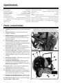
1. Fan – Rotating element which generates air ow
2. Fan Housing – Outer component which houses the fan
3. Intake Guard – Prevents ngers, hands, or large debris
from entering the fan housing and contacting the fan blades
4. Discharge Chute – The location where the air ow exits
the fan housing. Flow direction is to the left side of the
unit from machine operator’s position.
5. Flow Angle Adjustment – Vertically adjusts the direction
of air ow between 3 positions: level, 15 degrees up,
and 15 degrees down.
6. Front Flow Attachment – Redirects the air ow toward
the front of the unit. Can be removed and stored under
the frame when not in use.
7. Attachment Knob – Secures attachments to the dis-
charge chute
8. Front Swivel Wheel – 360 degree swiveling wheel to
allow for maneuverability.
9. ON/OFF Switch – Stops the engine when turned to
“OFF”. Must be turned to “ON” for engine to start and run.
10. Primer Bulb – Injects fuel mixture into the carburetor for
ease of starting the engine.
11. Muffler – Location of engine exhaust.
12. Air Filter – Removes debris and contaminates from
intake air, allowing engine to run smoothly and maintain
engine life.
13. Recoil Starter Handle – The engine is equipped with an
easy pull recoil starter.
14. Spark Plug/Spark Plug Wire – Provides spark to ignite air/
fuel mixture. The Spark Plug Wire must be disconnected
and moved away from the Spark Plug when servicing
the unit.
Spark Plug Model...................... Torch F7RTC
Spark Plug Gap ........... 0.028-0.031 in. (0.7-0.8 mm)
Engine Type ............. 4 Stroke, single cylinder, OHV
Displacement ............................... 163cc
RPM .................................. 3600 RPM
Torque Rating ......6.5 ft-lbs gross torque per SAE J1940
Bore Diam. x Stroke............ 2.7X1.8 in. (68X45 mm)
Intake Valve Clearance . 0.0032-0.0047 in.(0.08-0.12 mm)
Exhaust Valve Clearance . 0.0059-0.0079 in.(0.15-0.20mm)
Angle of Ignition . . . . . . . . . . . . . . . . . . . . . . . . 25 Degrees
5
Figure 1
FRONT VIEW
REAR VIEW
1
6
2
4
5
9
8
13
14
3
7
10
11
12
(inside)

Questions? Call Toll Free at 1-800-737-2112 Copyright © 2009 MAT Engine Technologies, LLC
Read and follow the assembly instructions. Do not discard any parts or materials until the unit is assembled.
References to the right or left side of the blower are from the viewpoint of the operator’s position behind the blower.
Assembly
• Save all instructions
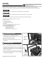
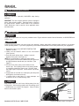
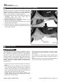
NOTE: There are two positions in which the handle can be
attached – a high position and a low position. (See Figure 2)
1. Assemble the handle tabs into the holes on the lower
frame tubing. Use the bottom holes for the low handle
position. Use the middle holes for the high handle
position. (See Figure 2)
2. Secure the handle onto the frame tubing with the (2) pipe
bolts and the (2) plastic wing nuts. Firmly hand-tighten
the wing nuts. (See Figure 2)
WARNING
Do not operate blower if it is damaged or not completely and correctly assembled.
WARNING
Before doing any assembly or maintenance to the unit, remove the wire from the spark plug.
WARNING
Always wear ANSI compliant safety glasses with side shields while assembling the blower.
The following components will be found in the carton.
Quantities shown in ( ).
1. (1) Walk Behind Blower
2. (1) Blower Operator’s Manual
3. (1) Handle
4. (1) Front Flow Attachment (stored under the frame)
5. (1) Bottle of SAE 30 Engine Oil
6. (1) Parts bag containing the following:
(2) Plastic Wing Nuts (M8)
(2) M8x35mm Pipe Bolts
(1) Spark plug socket wrench w/ rod
1. Remove all parts and packaging components.
2. Use a utility knife to cut all 4 vertical edges and lay the
side panels flat around the blower.
3. Remove any remaining packaging.
4. Roll the unit out from the carton, and place on a hard
level surface.
How to Remove Blower from Carton
A
How to Assemble the Handle
B
If you need assistance or find any parts missing, CALL
TOLL FREE: 1-800-737-2112.
6
Upper
Tube Hole
Frame Tubing
Pipe Bolt
Plastic
Wing Nut
Middle
Tube Hole
Handle
Bottom
Tube Hole
Handle Tab
Figure 2

Questions? Call Toll Free at 1-800-737-2112 Copyright © 2009 MAT Engine Technologies, LLC
Engine Preparation
• Save all instructions
Engine Oil
A
Engine shipped without oil. Failure to add oil will result in
serious engine damage.
A bottle of SAE 30 engine oil is included with your blower.
Refer to the chart on the right for alternative oil types to
use at different temperatures. Always use a high quality
detergent oil classified “For Service, SG, SH, SJ” or higher.
Do not use special additives.
Always use recommended oil type. Using dirty oil or
incorrect oil type such as 2-stroke engine oil will shorten
engine life.
NOTE: Engine Oil Capacity is 562 ml. For first time fill, simply
add the entire contents of the provided oil bottle to the
crankcase.
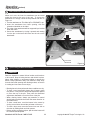
1. Set walk behind blower on a level surface.
2. Remove the oil ll cap/dipstick and wipe clean with cloth.
(See Figure 3)
3. Insert dipstick into ll spout but do NOT screw in.
Remove dipstick and check oil level.
4. When oil level is full, the oil will be at upper limit on dip
stick. If oil level is near or below the lower limit, oil must
be added. (See Figure 4)
5. Add oil slowly until the oil level reaches the upper limit of
the dipstick. Use a funnel or nozzle to reduce spillage.
CAUTION
Frequently check oil level while filling. DO NOT OVERFILL.
DO NOT UNDERFILL. Running engine at improper oil level
will seriously damage engine.
6. Replace and tighten dipstick.
7. Clean up any spilled oil.
HOW TO CHECK OIL LEVEL AND FILL TO PROPER LEVEL
Before checking oil, make sure engine is off, and spark plug wire has been disconnected from spark plug.
7
CAUTION
CAUTION
WARNING
SAE
TEMP
100° F
40° C
-20
-20-30 -10
0
0
20
2010
40
60 80
30
Ambient Service Temperature
SAE 10W-30
SAE 30
Oil Fill Cap/
Dipstick
Fuel Tank Cap
Oil Fill Cap/
Dipstick
Upper Limit
Lower Limit
Figure 3
Figure 4

Questions? Call Toll Free at 1-800-737-2112 Copyright © 2009 MAT Engine Technologies, LLC
Engine Preparation (Continued)
• Save all instructions
Fuel
B
Operation
• Save all instructions
Before Starting the Engine
A
WARNING
Before starting engine, read operator’s manual. Become familiar with location and function of all controls. Know how to
stop the engine quickly.
Before attempting to start the engine, review the following steps:
1. Unit has been assembled according to all assembly instructions.
2. Unit has been inspected for any damaged or missing components.
3. No parts are remaining in the carton.
4. Engine oil is at proper level.
5. Fresh, clean, regular-unleaded gasoline has been added to fuel tank.
6. Spark plug wire is connected to spark plug.
7. Blower has been moved to desired location.
8. Blower is on level surface.
WARNING
• Gasoline is extremely flammable and vapors can explode if ignited. Handle with care. Use fresh, clean, regular-unleaded
gasoline with a minimum of 88 Octane.
Do NOT use leaded gasoline, gasohol, methanol, or diesel fuel. Do NOT mix oil with gasoline. Do NOT allow gasoline to
become contaminated with dust, water, or debris.
CAUTION
Using incorrect fuel type or contaminated fuel will cause serious engine damage.
NOTE: Fuel tank capacity is approximately 3.5 qt (3.3L)
HOW TO FILL ENGINE WITH FUEL
WARNING
• Turn engine off and let engine cool for several minutes before removing the fuel cap or adding fuel.
• Never fill fuel tank indoors.
• Do not smoke while adding fuel.
1. Clean surface around fuel tank cap to prevent contamination. (See Figure 3)
2. Loosen fuel cap slowly. After removing cap, place on a clean surface.
3. Pour fuel into the tank. Use care to avoid spillage.
WARNING
Do NOT OVERFILL fuel. Allow space for the fuel to expand due to heat from engine and/or sun.
4. Before replacing the fuel cap, inspect and clean the fuel cap seal.
5. Replace the fuel cap and securely hand-tighten.
6. Clean up any spilled fuel.
8

Questions? Call Toll Free at 1-800-737-2112 Copyright © 2009 MAT Engine Technologies, LLC
Operation
• Save all instructions
Before Starting the Engine (Continued)
A
WARNING
Keep all bystanders, especially CHILDREN, away during
operation.
IMPORTANT: This unit’s engine exhaust system is equipped
with a spark-arresting muffler. Tampering with or removing
the spark-arrestor violates section 4442 of the California
Public Resources Code as well as other applicable state
and federal law.
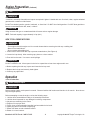
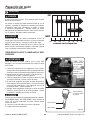
How to Start Engine
B
Never Run engine indoors or in a poorly ventilated area. Engine exhaust contains Carbon Monoxide, an ODORLESS and
DEADLY gas.
Debris thrown from blower can cause severe eye damage. Always wear ANSI compliant safety glasses or eye shields
when operating blower. If you wear eyeglasses, put an OSHA certified Wide Vision Safety Mask over your eyeglasses.
1. Review ALL steps in the “BEFORE STARTING THE
ENGINE” section.
2. Make sure the ON/OFF switch is in the ON Position
(See Figure 6)
3. Push the primer bulb 3 times - waiting 2 seconds
between each push. (See Figure 5)
NOTE: Not required when re-starting a warm engine.
4.
Firmly grip the Recoil Starter Handle with your right hand
and grip the blower handle with your left hand. (See
Figure 7)
5. Pull the recoil slowly, until you feel tension in the
starter rope. Then quickly pull the recoil starter handle
to completely unwind the starter rope. DO NOT allow
the starter rope to snap back. Let the starter rope slowly
rewind.
6. If engine fails to start after 3 or 4 attempts, push the primer
bulb again 2 more times and retry.
7. If engine fails to start after 6 or more attempts, see
instructions in the “Troubleshooting Chart”
DANGER
WARNING
Keep hands, feet, hair, and loose clothing away from any
moving parts. Avoid touching muffler and surrounding areas
– temperatures can exceed 150 degrees. Keep all safety
devices and shields in place.
ON/OFF
Switch
9
OFF Position
ON Position
Primer Bulb
ON/OFF Switch
Recoil
Starter
Handle
WARNING
Figure 5
Figure 6
Figure 7

Questions? Call Toll Free at 1-800-737-2112 Copyright © 2009 MAT Engine Technologies, LLC
Operation (Continued)
• Save all instructions
How to Stop the Blower
C
Move the ON/OFF Switch to the OFF position. (See gure 6)
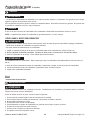
How to Adjust the Vertical Flow Angle
D
The vertical air flow direction can be adjusted between
3 positions: Straight (level), 15 degrees upward, and 15
degrees downward. Refer to Figure 8 when performing the
adjustment steps below:
1. Stop the engine.
2. Pull the index lever out of its existing hole.
3. Rotate the index lever to the desired position.
4. Release the index lever and allow it to insert into the
desired hole.
WARNING
Never adjust the flow angle when engine is running. Never
stand or put your hand in front of the discharge opening
when the engine is running. Never put hands, fingers, or
anything else inside the discharge opening when the engine
is running. There are rotating blades inside which can cause
serious injury.
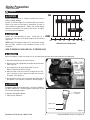
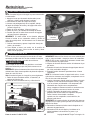
How to Redirect Air Flow toward the Front
E
A Front Flow Attachment is included with your blower. Assembling this attachment to the blower will cause the air flow to
be redirected to the front of the blower.
Adjustment
Lever
Level
15° Upward
Air Flow
Louver
10
To assemble this attachment to the blower, follow the steps
below and refer to Figure 9:
1. Stop the engine.
2. Rotate the vertical adjustment lever to the level position
(See Figure 8)
3. Loosen the attachment knob located on top of the blower
discharge chute
4. Orient the attachment so the “This Side Up For USE” is up.
5. Slide the front flow attachment over the discharge
chute with the orientation identified on the label. The slot
on the top of the front flow attachment will mate
with the bolt of the attachment knob.
6. Hand-tighten the attachment knob to secure the
attachment.
Note: when properly assembled, the attachment knob will fit
inside of the round emboss on the top of the attachment.
15° Downward
Discharge
Chute
Bolt
Round
Emboss
Slot
Attachment
Knob
Front Flow
Attachment
Figure 8
Figure 9

Questions? Call Toll Free at 1-800-737-2112 Copyright © 2009 MAT Engine Technologies, LLC
Operation (Continued)
• Save all instructions
When not in use, the front flow attachment can be stored
under the frame at the rear of the unit. To secure the
attachment for storage, follow the steps below and refer to
Figure 10:
1. Turn the attachment so “This Side Up For STORAGE” is up.
2. Insert the attachment into frame opening, with the
orientation identified on the label.
3. The edge of the attachment will be supported by a bracket
under the frame.
4. Secure the attachment by forcing it upward and rotating
it so the pin on the frame will insert into the slot on the
attachment.
Support
Rod
Slot
Front Flow
Attachment
11
How to Redirect Air Flow toward the Front (Continued)
E
Tips for Using your Walk Behind Blower
E
WARNING
Read the Operator’s manual. Know location and functions
of all controls. Keep all safety devices and shields in place.
Never allow children or uninstructed adults to operate the
blower. Keep bystanders away from machine. Keep away
from the fan intake opening and discharge chute, as the fan
is rotating and can cause severe injury.
• Blowing leaves is best performed when conditions are dry.
• To clear a very large and/or heavy pile of leaves, make
two passes: First point the directional adjustment upward
to move the top of the pile. Then point the directional
adjustment downward to move the base of the pile.
• When clearing leaves, always pay attention to natural
wind direction and blow the leaves the same direction as
the natural wind.
• To clear a small area, corral the leaves in the center by
circling several times around the perimeter of the area.
• To clear a large area, move the leaves from one side to
the other by making back and forth passes.
• Before starting a cleaning project, plan how the leaves will
be collected and disposed.
Figure 10

Questions? Call Toll Free at 1-800-737-2112 Copyright © 2009 MAT Engine Technologies, LLC
Maintenance
• Save all instructions
Maintenance Schedule
A
Before performing any maintenance, turn engine off and remove the wire from the spark plug to prevent accidental starting
and serious injury.
IMPORTANT: The warranty on this blower does not cover items that have been subjected to operator abuse or negligence.
To receive full value from the warranty, the operator must maintain the blower as instructed in this manual, and only use
genuine replacement parts. The following table lists required periodic maintenance.
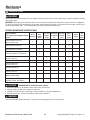
PERIODIC MAINTENANCE SCHEDULE TABLE
IMPORTANT NOTES about Maintenance schedule
1. Re-check tightness of all fasteners after first 2 hours of initial use.
2. Change engine oil after first 5-8 hours of initial use.
3. Change oil every 25 hours if operating in dusty conditions or in high temperatures.
4. Clean air filter every 10 hours if operating under dusty conditions.
Use only GENUINE replacement parts. Other parts may damage the unit or result in injury.
CAUTION
Service Records-
Fill in dates as you complete regular
service
Before
Each Use
After
Every
10 Hours
of Use
After Every
25 Hours
of Use
After Every
50 Hours of
Use
After Every
100 Hour
of Use
Before
Each
Season
Before
Storage
See
Note
Below
Check Engine Oil Level,
Fill to Proper Level
√ √
Clean Debris From Unit
√ √ √
Lubricate All Pivot Points
√ √ √
Check Fasteners for Tightness
√ √
1
Check Fuel Line
Replace if Necessary
√ √
Lubricate Wheel Axles
√ √ √
Check Spark Plug
Replace if Necessary
√ √
Change Engine Oil
√ √ √
2,3
Clean Air Filter
Replace if Necessary
√ √
4
Replace Spark Plug
√
Clean Combustion Deposits from
Cylinder, Piston, and Valves
√
WARNING
12
WARNING

Questions? Call Toll Free at 1-800-737-2112 Copyright © 2009 MAT Engine Technologies, LLC
Maintenance (Continued)
• Save all instructions
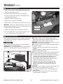
How to Change the Engine Oil
B
1. Stop the engine and let it cool.
2. Disconnect spark plug wire from the spark plug.
3. Insert a flat pan under the blower, underneath the oil
drain plug and frame hole.
4. Remove oil dipstick. (See Figure 3)
5. Remove the oil drain bolt and washer.
6. Allow all oil to drain through the frame hole into the pan.
IMPORTANT: Used oil is a hazardous waste. Place oil in a
sealed container and take to your local recycling center. Do
NOT discard with household waste.
7. Replace and tighten the oil drain plug and washer.
8. To re-fill engine with oil, see engine preparation section
“How to Check Oil and Fill to Proper Level.”
NOTE: Refer to Figure 11 when following the steps below:
13
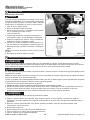
How to Clean the Air Filter
C
A dirty air filter will restrict air intake. Regular maintenance
of air cleaner will help improve engine performance and
reduce emissions.
Never clean air filter with gasoline or an easy ignited sol-
vent because it may cause explosion.
IMPORTANT: Only use replacement air filter from the manu-
facturer. To order spare parts call us at 1-800-737-2112
NOTE: Refer to Figure 12 when following steps below:
1. Remove the outer wing nut, washer, and air filter cover.
2. Remove the inner wing nut, and the air filter.
IMPORTANT: Use care when removing the air filter so dirt and
debris does not fall into the carburetor.
NOTE: Air filter is made up of an outer foam element and an
inner paper element.
3. Separate the outer foam element from the inner paper
element.
4.
Check the inside of the paper element for dirt or debris.
5. Check both elements for tears.
NOTE: If the inner paper element is dirty or if either element is
torn, replace with a new air filter from the manufacturer.
6. Clean the outer foam element by washing it thoroughly in
a solution of household detergent and water, or in a
nonflammable or high flash point solvent. Allow to
dry thoroughly. Then soak the foam element in clean
engine oil, and squeeze out all excess oil.
7. Clean the inner paper element by lightly tapping it
against a hard surface to remove excess dirt or by
blowing compressed air through the filter from the
inside out.
IMPORTANT: Do not attempt to brush dirt off the paper ele-
ment, as this will only embed dirt into the fibers.
8. Reinstall the cleaned out foam element onto the inner
paper element.
9. Reinstall the clean air filter and cover onto the unit by
reversing steps 1 and 2 above.
WARNING
Outer Wingnut
Washer
Air Filter Cover
Air Filter Element
Inner Wingnut
Figure 12
Drain Plug
and Washer
Figure 11
Frame Hole

Questions? Call Toll Free at 1-800-737-2112 Copyright © 2009 MAT Engine Technologies, LLC
Maintenance (Continued)
• Save all instructions
14
How to Check the Spark Plug
G
Spark Plug Model: Torch F7RTC
CAUTION
Only use the recommended spark plug or a spark plug with
the same temperature range. Using an improper spark
plug, an incorrect spark plug gap, or a dirty/fouled spark
plug can reduce engine performance and cause damage.
1. Stop engine and allow it to cool.
2. Remove spark plug wire from spark plug.
3.
Use the spark plug wrench and rod (included with blower)
to remove the spark plug. (See Figure 13)
4. Visually inspect the spark plug for cracks or damage. If
cracked, replace spark plug.
5. Clean carbon deposits. If excessive carbon build up,
replace spark plug.
6. Check that the gap of the spark plug is 0.028-0.031 in.
(0.7-0.8 mm). (See Figure 14)
7. Re-insert the spark plug and tighten using the spark
plug wrench and rod. (See Figure 13)
NOTE: Torque of spark plug is 18-22 foot-pounds (25-30 Nm)
8. Reattach spark plug wire to spark plug.
Spark Plug
Wrench
and Rod
Figure 13
0.028 - 0.031 in
0.7 - 0.8 mm
Figure 14
How to Prepare for Storage
H
WARNING
Never store the blower indoors with fuel in the fuel tank. Never store in an enclosed, poorly ventilated area where fumes
could reach an open ame, a spark or a pilot light as on a furnace, water heater or clothes dryer. Allow engine to cool
before storing unit.
WARNING
Do not remove gasoline while inside a building, near a re, or while you smoke. Gasoline fumes can cause an explosion
or a re.
NOTE: A yearly checkup or tune-up at an authorized service center will make sure that the blower will provide maximum
performance for the next season.
When the blower is put in storage for thirty days or more, the following steps should be followed to make sure the blower is in
good condition the next season.
1. Let the engine run until it is out of gasoline.
2. Change the oil by following instructions under “How to Change the Oil.”
3. Remove the spark plug from the cylinder. Pour one ounce of oil into the cylinder. Slowly pull the recoil-start grip so
that the oil will protect the cylinder. Install a new spark plug in the cylinder. Pull starter handle slowly a few times to
distribute oil. Pull recoil slowly until resistance is felt. This will close the cylinder valves.
WARNING
DO NOT attach spark plug wire to spark plug when storing unit.
4. Clean blower. Remove all dirt, leaves, debris, grease, etc. from the blower - including cylinder cooling fans, recoil
starter cover holes, under fuel tank, and under mufer.
5. Check the blower for worn or damaged parts. Have damaged parts replaced if necessary.
6. Tighten any loose hardware.
7. Apply lubrication as directed in Maintenance section.
8. Put the unit in a building that has good ventilation.
9. Cover the blower with a breathing material.

Questions? Call Toll Free at 1-800-737-2112 Copyright © 2009 MAT Engine Technologies, LLC
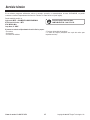
You may have further questions about assembling, operating, or maintaining this Blower. If so, you can contact our
Technical Service Department at 1-800-737-2112 (English only).
You may also write to:
METL Corporate Office - CORRESPONDENCE ONLY
ATTN: Technical Service – METL
6700 Wildlife Way
Long Grove, IL 60047
Technical Service
When contacting the Technical Service Department, have ready:
• Your Name
• Your Address
• Your Phone Number
• Model Number of Product
• Date of Purchase (include copy of receipt for written requests)
If you need assistance or have any questions, CALL
TOLL FREE: 1-800-737-2112.
15

Questions? Call Toll Free at 1-800-737-2112 Copyright © 2009 MAT Engine Technologies, LLC
16
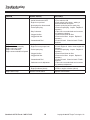
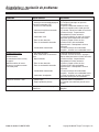
PROBLEM POSSIBLE CAUSE(S) SOLUTION(S)
Engine difficult to start 1. Out of fuel
2. On/Off Switch turned OFF
3. Engine is not primed.
4. Spark plug wire disconnected
5. Fouled spark plug
6. Dirty Carburetor
7. Clogged air filter
8. Clogged fuel filter
9. Contaminated Fuel
1. Add fresh fuel
2. Turn switch to ON
3. Push primer bulb 3 times - waiting 2
seconds between each push.
4. Attach spark plug wire to spark plug
5. Remove spark plug. Inspect. Replace if
necessary
6. Take unit to an authorized service center
for Carburetor cleaning
7. Remove and clean air filter
8. Remove fuel filter. Inspect. Replace if
necessary
9. Drain fuel tank. Clean fuel tank. Fill with
fresh fuel
Engine Problems
Engine smokes excessively
Engine runs very “rough”
Engine runs erratically
Engine cannot maintain full speed
1. No Engine Oil
2. Engine oil not at proper level
3. Fouled spark plug
4. Clogged air filter
5. Clogged fuel filter
6. Contaminated Fuel
7. Carburetor out of adjustment
1. Add engine oil
2. Check engine oil. Add or drain engine oil if
necessary
3. Remove spark plug. Inspect. Replace if
necessary
4. Remove and clean air filter
5. Remove fuel filter. Inspect. Replace if
necessary
6. Drain fuel tank. Clean fuel tank. Fill with
fresh fuel
7. Take unit to an authorized service center
for Carburetor adjustment
Excessive vibration / noise 1. Loose parts
2. Engine problems (above)
1. Tighten all fasteners
2. Refer to engine solutions (above)
Engine will not stop Defective On/Off Switch Replace On/Off Switch
Troubleshooting
• Save all instructions

Questions? Call Toll Free at 1-800-737-2112 Copyright © 2009 MAT Engine Technologies, LLC
Warranty
• Save all instructions
Always specify model number when contacting the factory.
We reserve the right to amend these specifications at any time without notice. The only warranty applicable is our standard written war-
ranty. We make no other warranty, expressed or implied. MAT Engine Technologies, LLC warrants this Blower and any parts thereof,
to be free from defects in material and workmanship for two years (90 days for commercial use or for reconditioned unit) from the date
of first purchase from an authorized dealer, provided that the product has been properly maintained and operated in accordance with
all applicable instructions. This warranty is extended only to the original retail purchaser. The bill of sales or proof of purchase must
be presented at the time a claim is made under this warranty. This warranty does not cover commercial, industrial, or rental usage,
nor does it apply to parts that are not in original condition because of normal wear and tear, or parts that fail or become damaged as a
result of misuse, accident, lack of proper maintenance, tampering, or alteration. Travel, handling, transportation, and incidental costs
associated with warranty repairs are not reimbursable under this warranty and are the responsibility of the owner. To the full extent
allowed by the law of the jurisdiction that governs the sale of the product, this express warranty excludes any and all other expressed
warranties and limits the duration of any and all implied warranties, including warranties of merchantability and fitness for a particular
purpose to two years from the date of first purchase, and MAT Engine Technologies, LLC’s liability is hereby limited to the purchase
price of the product and MAT Engine Technologies, LLC shall not be liable for any other damages whatsoever including indirect,
incidental, or consequential damages. Some states do not allow limitation of how long an implied warranty lasts or an exclusion or
limitation of incidental or consequential damages, so the above limitation of damages may not apply to you. This warranty provides the
original purchaser with specific rights.
For information regarding those rights, please consult the applicable state laws.
METL Corporate Office - CORRESPONDENCE ONLY
ATTN: Technical Service – METL
6700 Wildlife Way
Long Grove, IL 60047
Powermate® WALK BEHIND BLOWER Limited Warranty
A
17

Questions? Call Toll Free at 1-800-737-2112 Copyright © 2009 MAT Engine Technologies, LLC
18
Warranty (Continued)
• Save all instructions
This MAT Engine Technologies, LLC (METL) outdoor power equipment engine complies with the emissions regulations of:
To the extent there is any conflict between this Emissions Control System Warranty and the equipment manufacturer’s warranty, this
Emissions Control System Warranty shall apply except where the equipment manufacturer’s warranty may provide a longer warranty
period. Please read your warranty rights and obligations carefully. Some sections of the warranty may not apply to the specific equipment
model you purchased. Unless specifically noted otherwise, the terms of the Emission Control System Warranty shall apply to all product
engines covered within this manual.
The California Air Resources Board, U.S. EPA and MAT Engine Technologies, LLC (METL) are pleased to explain the Emission Control Sys-
tem Warranty on your new outdoor power equipment engine.
California (applies only to Model No. P-WB-163150)
In California, new spark-ignited small off-road equipment engines must be designed, built and equipped to meet the State’s stringent
anti-smog standards.
Other States, U.S. Territories
In other areas of the United States, your engine must be designed, built and equipped to meet the U.S. EPA emission standards for spark-
ignited engines at or below 19 kilowatts.
All of the United States
MAT Engine Technologies, LLC (METL) must warrant the emissions control system on your power equipment engine for the periods of time
listed below provided there has been no abuse, neglect or improper maintenance of your power equipment engine. Where a warrantable
condition exists, METL will repair your power equipment engine at no cost to you including diagnosis, parts and labor.
The emissions control system is warranted for two years. If any emissions-related part on your engine is defective, the part will be repaired
or replaced by METL.
Owner’s Warranty Responsibility
As the power equipment engine owner, you are responsible for the performance of the required maintenance listed in your owner’s
manual. METL recommends that you retain all receipts covering maintenance on your power equipment engine, but METL can not deny
warranty solely for the lack of receipts or for your failure to ensure the performance of all scheduled maintenance.
As the power equipment engine owner, you should however be aware that METL may deny your warranty coverage if your power equip-
ment engine or a part has failed due to abuse, neglect, improper maintenance or unapproved modifications.
You are responsible for presenting your power equipment engine to a distribution center or service center authorized by METL as soon as
the problem exists. The warranty repairs should be completed in a reasonable amount of time, not to exceed 30 days.
If you have any questions regarding your warranty rights and responsibilities, you should contact
MAT Engine Technologies, Inc.
6700 Wildlife Way
Long Grove, IL 60047
Tel: 1-800-737-2112
Your Warranty Rightes and Obligations:
Emisson Control System Warranty
B
Powermate® Model No. Regulatory Agency
P-WB-163150-[E] United States Environmental Protection Agency (“U.S. EPA”)
P-WB-163150 United States Environmental Protection Agency (“U.S. EPA”) and State of California
Manufacturer’s Warranty Coverage:

Questions? Call Toll Free at 1-800-737-2112 Copyright © 2009 MAT Engine Technologies, LLC
METL warrants that the product engine is free from defects in materials and workmanship which cause such engine to fail to conform
with the U.S. EPA or State of California emissions standards for small spark-ignited nonroad (off-road) engines – as applicable to your
METL product. Small spark-ignited off-road engines manufactured after January 1, 1995 and sold in the State of California and U.S. EPA-
certified small spark-ignited nonroad engines manufactured in model year 1997 or later and sold in all of the United States are covered
by this Emission Control System Warranty for a period of two years from the date of delivery to the original purchaser. This Emission
Control System Warranty is transferable to each subsequent purchaser for the duration of the warranty period. Emission Control System
Warranty repairs or replacements will be made without charge for diagnosis, parts or labor. A list of warranted parts is provided below.
Normal maintenance items, such as spark plugs, air filters and fuel filters that are included on the list of warranted parts are warranted
only up to the first scheduled required replacement interval for such item, as set forth in the Operator’s Manual. If any emission control
system part is repaired or replaced under the Emission Control System Warranty, it shall be warranted for the remainder of the applicable
warranty period. METL will also repair or replace other engine components damaged by a failure of any part covered by the Emission Con-
trol System Warranty during the Emission Control System Warranty Period. Only parts authorized and approved by METL may be used
in the performance of any Emission Control System Warranty repairs or replacements and will be provided without charge to the owner.
Unapproved, add-on, modified, counterfeit and/or “gray market” parts may not be used to modify or repair the METL engine. If such a part
has been used in the repair or maintenance of your engine, and an METL Authorized Service Center determines it is defective or causes a
failure of a part covered under the Emission Control System Warranty, your claim for repair of your engine or product may be disallowed.
METL shall not be held liable hereunder for failures of any warranted parts caused by the use of such an unapproved, add-on, modified,
counterfeit and/or “gray market” part.
You must take your power equipment engine or the product on which it is installed, along with evidence of the date of the sale to the
original purchaser, at your expense, to any METL Authorized Service Center during its normal business hours. To locate your nearest METL
Authorized Service Center, call (800) 737-2112. The product owner shall be responsible for any expenses or charges incurred for service
calls or transportation of the product or equipment engine to and from the METL Authorized Service Center, including any and all damages
or losses incurred during such transportation or shipment.
Failures other than those resulting from defects in material or workmanship are not covered by this Emission Control System Warranty.
This Emission Control System Warranty does not extend to emission control systems or parts which are affected or damaged by owner
abuse, neglect, improper maintenance, misuse, mis-fueling, improper storage, accident and/or collision, the incorporation of, or any use
of, any unapproved, add-on, modified, “graymarket” or counterfeit parts, unsuitable attachments, or the unauthorized alteration of any
part. This Emission Control System Warranty does not cover the regular replacement of normal maintenance items made in connection
with required maintenance services after the item’s first scheduled replacement, as set forth in the Operator’s Manual (e.g. spark plugs,
air filters, fuel filters, etc...).
METL disclaims any responsibility for loss of time or use of the engine, or the equipment in which the engine is installed, transportation,
commercial loss, or any other incidental or consequential damage. Any implied warranties are limited to the duration of this written limited
warranty. Some states do not allow limitations on how long an implied warranty lasts and/or do not allow the exclusion or limitation of
incidental or consequential damages, so the above exclusions and limitations may not apply to you.
This warranty gives you specific legal rights, and you may also have other rights which vary from state to state.
Warranty (Continued)
• Save all instructions
How to Obtain Warranty Service:
Exclusions:
Limitations of Liability:
Warranty Coverage:
19
Page is loading ...
Page is loading ...
Page is loading ...
Page is loading ...
Page is loading ...
Page is loading ...
Page is loading ...
Page is loading ...
Page is loading ...
Page is loading ...
Page is loading ...
Page is loading ...
Page is loading ...
Page is loading ...
Page is loading ...
Page is loading ...
Page is loading ...
Page is loading ...
Page is loading ...
Page is loading ...
Page is loading ...
Page is loading ...
Page is loading ...
Page is loading ...
-
 1
1
-
 2
2
-
 3
3
-
 4
4
-
 5
5
-
 6
6
-
 7
7
-
 8
8
-
 9
9
-
 10
10
-
 11
11
-
 12
12
-
 13
13
-
 14
14
-
 15
15
-
 16
16
-
 17
17
-
 18
18
-
 19
19
-
 20
20
-
 21
21
-
 22
22
-
 23
23
-
 24
24
-
 25
25
-
 26
26
-
 27
27
-
 28
28
-
 29
29
-
 30
30
-
 31
31
-
 32
32
-
 33
33
-
 34
34
-
 35
35
-
 36
36
-
 37
37
-
 38
38
-
 39
39
-
 40
40
-
 41
41
-
 42
42
-
 43
43
-
 44
44


Powermate P-WB-163150-[E] User manual
- Category
- Air blowers/dryers
- Type
- User manual
- This manual is also suitable for
Ask a question and I''ll find the answer in the document
Finding information in a document is now easier with AI
in other languages
Related papers
-
Powermate SWB163150E User manual
-
-
-
-
-
-
-
-
Powermate SFTT142 User manual
-
Other documents
-
Craftsman CMXGAAM1359134 User guide
-
Southland Walk Behind Blower User manual
-
Troy-Bilt 24A67M4710 User manual
-
-
-
-
-
-
-