4
DEVICE PAIRING USING PUSH-TO-PAIR MODE
Push-to-Pair in a room with a single LMRC-611MCC Room Controller
NOTE: Once you enter PtP mode on the room controller, a two minute timer begins. If the Config button on any
device in the room is pressed, the timer resets and begins the two minute countdown again. If no Config
button is pressed within 2 minutes, the room controller will exit PtP mode.
1. Enter PtP mode on the room controller. Press the Config button three times (within three seconds) until the
LED on the room controller flashes green.
2. Enter PtP mode on the LMPX-600. Using a pointed tool, press the Config button three times. As with the room
controller, the LED on the switch will flash green.
3. Pair the LMPX-600. Press the Config button on the LMPX-600 once to pair it to the room controller. The load
connected to the room controller will toggle once (if the load is OFF, it will turn ON; if ON, it will turn OFF) to
indicate that pairing was successful.
NOTE: If there are any wireless sensors, dimmers, or additional switches in the room, repeat steps 2 and 3
for each of those devices so that all devices are paired together in the same network. For each device, the
load will toggle during step 3.
4. Exit PtP mode. Exit PtP on the room controller, by pressing the Config button 3 times. The LED on the room
controller will flash blue while it completes the pairing process. The default PAN ID on all devices will change to
a new number, based on the last four digits of the Mac address on the room controller, and now those devices
will communicate only with each other and not any devices which have not been paired. Once complete, the switches and sensors
will automatically exit PtP mode and will reboot. The LED on each switch or sensor will flash white at least once before resuming
normal operation.
NOTE: It is important to exit PtP mode within the 2 minute time limit mentioned above. If you do not, none of the device pairings
will be remembered and you have to start the process over from the beginning.
Push-to-Pair in a room with multiple LMRC-611MCCs
In a room with multiple loads, there may be more than one LMRC-611MCC. They can all be paired to the same room network, allowing
the scene switch to set each load to different levels per scene. One of the room controllers will become the master, determining the PAN
ID and channel settings for all the devices in the network.
1. Enter wireless Push-to-Pair (PtP) mode on all room controllers. Press the Config button three times on each LMRC-611MCC
to put them all in PtP mode. The green LEDs will flash on all room controllers.
2. Enter PtP mode on the LMPX-600. Using a pointed tool, press the Config button three times. As with the room controller, the
LED on the switch will flash green.
3. Pair the LMPX-600. Press the Config button on the LMPX-600 once to pair it to the room controller. The load connected to the
room controller will toggle once (if the load is OFF, it will turn ON; if ON, it will turn OFF) to indicate that pairing was successful.
NOTE: If there are any wireless sensors, dimmers, or additional switches in the room, repeat steps 2 and 3 for each of those
devices so that all devices are paired together in the same network. For each device, the load will toggle during step 3.
4. Pair the room controllers together. Press the Config button once on each room controller. This indicates to the rooms controllers
that they will be paired with each other.
5. Exit PtP mode. On one of the room controllers, press the Config button 3 times. This room controller will become the master. The
LED on the room controller will flash blue while it completes the pairing process. The default PAN ID on all devices will change to
a new number, based on the last four digits of the Mac address on the room controller, and now those devices will communicate
only with each other and not any devices which have not been paired. Once complete, the switches and sensors will automatically
exit PtP mode. The LED on each switch or sensor will flash white at least once before resuming normal operation.
NOTE: It is important to exit PtP mode within the 2 minute time limit mentioned above. If you do not, none of the device pairings
will be remembered and you have to start the process over from the beginning.
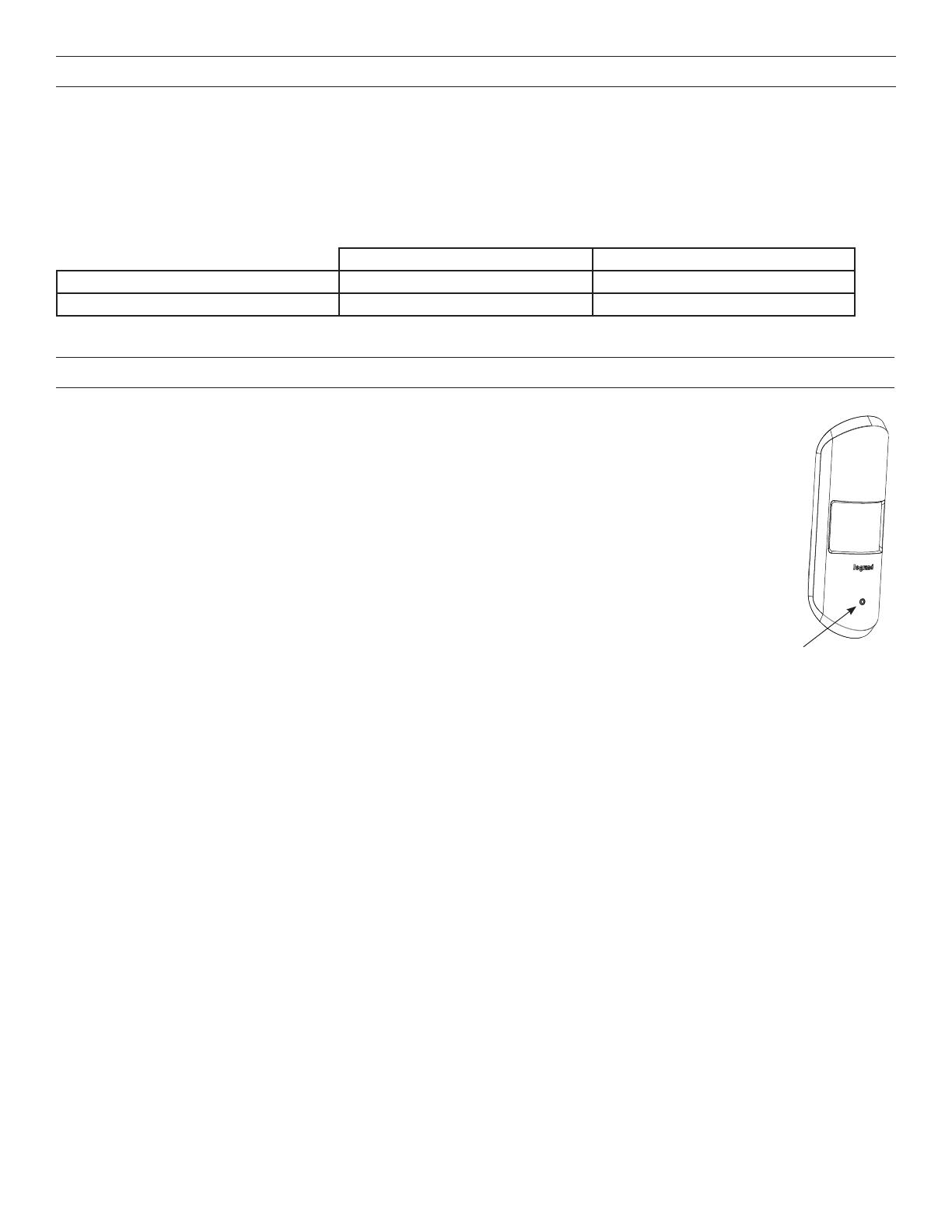
Press to pair to
room controller
SETTING UP A ROOM NETWORK BY PAIRING DEVICES
Pair wireless devices to a room controller to create a secure individual room network and enable Plug N’ Go operation.
Device pairing can be done by using Push-to-Pair (PtP) mode on the room controller and all other wireless devices, or by using the DLM
Config App.
To pair devices in a network, they must all have the same wireless channel and PAN ID. By default the channel is 15 and the PAN ID is 1.
Using Push-toPair mode, the PAN ID for all devices being paired is migrated to a new number, so that only those device communicate
with each other. Note that while the channel remains at its default value using Push-to-Pair, if you pair devices using the DLM Config
app, you can also change the channel.
Recommended Pairing Methods for Different Scenarios
Rooms with One Room Controller Rooms with Multiple Room Controllers
Set Up a new room network DLM Config App or Push-to-Pair Mode DLM Config App or Push-to-Pair Mode
Add a device to an existing room network DLM Config App or Push-to-Pair Mode DLM Config App
NOTE: LMCS-100 software, version 4.7 or later can also be used to pair devices. However, LMCS-100 requires use of an LMBR-650.


