Page is loading ...

User's Guide
SLAU217A–July 2007–Revised January 2014
TLV320AIC3105EVM and TLV320AIC3105EVM-PDK
This User's Guide describes the characteristics, operation, and use of the TLV320AIC3105EVM, both by
itself and as part of the TLV320AIC3105EVM-PDK. This evaluation module (EVM) is a complete stereo
audio codec with several inputs and outputs, extensive audio routing, mixing, and effects capabilities. A
complete circuit description, schematic diagram, and bill of materials are also included.
The following related documents are available through the Texas Instruments website at www.ti.com.
EVM-Compatible Device Data Sheets
Device Literature Number
TLV320AIC3105 SLAS513
TAS1020B SLES025
REG1117-3.3 SBVS001
TPS767D318 SLVS209
SN74LVC125A SCAS290
SN74LVC1G125 SCES223
SN74LVC1G07 SCES296
Contents
1 EVM Overview ............................................................................................................... 3
2 EVM Description and Basics .............................................................................................. 3
3 TLV320AIC3105EVM-PDK Setup and Installation ..................................................................... 8
4 TLV320AIC3105EVM Software .......................................................................................... 10
Appendix A EVM Connector Descriptions ................................................................................... 33
Appendix B TLV320AIC3105EVM Schematic ............................................................................... 37
Appendix C TLV320AIC3105EVM Layout Views ........................................................................... 38
Appendix D TLV320AIC3105EVM Bill of Materials ......................................................................... 41
Appendix E USB-MODEVM Schematic ...................................................................................... 42
Appendix F USB-MODEVM Layout Views .................................................................................. 44
Appendix G USB-MODEVM Bill of Materials ................................................................................ 46
Appendix H USB-MODEVM Protocol ......................................................................................... 48
List of Figures
1 TLV320AIC3105EVM-PDK Block Diagram ............................................................................. 4
2 Default Software Screen .................................................................................................. 9
3 Device Selection Window ................................................................................................ 10
4 Preset Configuration Tab................................................................................................. 12
5 Audio Input/ADC Tab ..................................................................................................... 13
6 Bypass Paths Tab......................................................................................................... 14
7 Audio Interface Tab ...................................................................................................... 15
8 Clocks Tab ................................................................................................................. 16
9 AGC Tab ................................................................................................................... 18
Microsoft, Windows are registered trademarks of Microsoft Corporation.
SPI is a trademark of Motorola, Inc.
VISA, LabVIEW are trademarks of National Instruments Corporation.
All other trademarks are the property of their respective owners.
1
SLAU217A–July 2007–Revised January 2014 TLV320AIC3105EVM and TLV320AIC3105EVM-PDK
Submit Documentation Feedback
Copyright © 2007–2014, Texas Instruments Incorporated

www.ti.com
10 Left AGC Settings ......................................................................................................... 19
11 Advanced................................................................................................................... 19
12 Filters Tab ................................................................................................................. 20
13 ADC High-Pass Filters ................................................................................................... 21
14 ADC High-Pass Filter Settings .......................................................................................... 21
15 DAC Filters ................................................................................................................. 22
16 De-emphasis Filters....................................................................................................... 22
17 Enabling Filters ........................................................................................................... 23
18 Shelf Filters ................................................................................................................ 23
19 EQ Filters .................................................................................................................. 24
20 Analog Simulation Filters ................................................................................................ 24
21 Preset Filters .............................................................................................................. 25
22 User Filters ................................................................................................................ 25
23 3D Effect Settings ........................................................................................................ 26
24 Output Stage Configuration Tab ........................................................................................ 27
25 DAC/Line Outputs Tab ................................................................................................... 28
26 High Power Outputs Tab ................................................................................................ 30
27 Command Line Interface Tab ........................................................................................... 31
28 File Menu .................................................................................................................. 32
29 TLV320AIC3105EVM Assembly Layer ................................................................................. 38
30 TLV320AIC3105EVM Top Layer ........................................................................................ 38
31 TLV320AIC3105EVM Layer 3 ........................................................................................... 39
32 TLV320AIC3105EVM Layer 4 ........................................................................................... 39
33 TLV320AIC3105EVM Silk Screen....................................................................................... 40
34 TLV320AIC3105EVM Bottom Layer .................................................................................... 40
35 USB-MODEVM Interface Board Schematic (1 of 2) .................................................................. 42
36 USB-MODEVM Interface Board Schematic (2 of 2) .................................................................. 43
37 USB-MODEVM Assembly Layer ........................................................................................ 44
38 USB-MODEVM Top Layer ............................................................................................... 44
39 USB-MODEVM Bottom Layer ........................................................................................... 45
List of Tables
1 USB-MODEVM SW2 Settings............................................................................................. 5
2 USB-MODEVM Jumpers................................................................................................... 5
3 List of Jumpers.............................................................................................................. 6
4 Analog Interface Pinout................................................................................................... 33
5 Alternate Analog Connectors ............................................................................................ 34
6 Digital Interface Pinout.................................................................................................... 35
7 Power Supply Pinout...................................................................................................... 36
8 TLV320AIC3105EVM Bill of Materials.................................................................................. 41
9 USB-MODEVM Bill of Materials ......................................................................................... 46
10 USB Control Endpoint HIDSETREPORT Request.................................................................... 48
11 Data Packet Configuration ............................................................................................... 48
12 GPIO Pin Assignments ................................................................................................... 51
2
TLV320AIC3105EVM and TLV320AIC3105EVM-PDK SLAU217A–July 2007–Revised January 2014
Submit Documentation Feedback
Copyright © 2007–2014, Texas Instruments Incorporated

www.ti.com
EVM Overview
1 EVM Overview
1.1 Features
• Full-featured evaluation board for the TLV320AIC3105 stereo audio codec.
• Modular design for use with a variety of digital signal processor (DSP) and microcontroller interface
boards.
• USB connection to PC provides power, control, and streaming audio data for easy evaluation.
• Onboard microphone for ADC evaluation
• Connection points for external control and digital audio signals for quick connection to other
circuits/input devices.
The TLV320AIC3105EVM-PDK is a complete evaluation kit, which includes a universal serial bus (USB)-
based motherboard and evaluation software for use with a personal computer running the Microsoft
®
Windows
®
operating system (Windows 2000, Windows XP, or Windows 7).
1.2 Introduction
The TLV320AIC3105EVM is in the Texas Instruments modular EVM form factor, which allows direct
evaluation of the device performance and operating characteristics, and eases software development and
system prototyping. This EVM is compatible with the 5-6K Interface Evaluation Module (SLAU104) and the
HPA-MCUINTERFACE (SLAU106) from Texas Instruments and additional third-party boards which
support TI's Modular EVM format.
The TLV320AIC3105EVM-PDK is a complete evaluation/demonstration kit, which includes a USB-based
motherboard called the USB-MODEVM interface board and evaluation software for use with a personal
computer running the Microsoft Windows operating systems.
The TLV320AIC3105EVM-PDK is operational with one USB cable connection to a personal computer. The
USB connection provides power, control, and streaming audio data to the EVM for reduced setup and
configuration. The EVM also allows external control signals, audio data, and power for advanced
operation, which allows prototyping and connection to the rest of the development or system evaluation.
2 EVM Description and Basics
This section provides information on the analog input and output, digital control, power and general
connection of the TLV320AIC3105EVM.
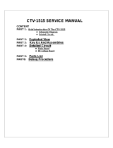
2.1 TLV320AIC3105EVM-PDK Block Diagram
The TLV320AIC3105EVM-PDK consists of two separate circuit boards, the USB-MODEVM and the
TLV320AIC3105EVM. The USB-MODEVM is built around a TAS1020B streaming audio USB controller
with an 8051-based core. The motherboard features two positions for modular EVMs, or one double-wide
serial modular EVM may be installed. The TLV320AIC3105EVM is one of the double-wide modular EVMs
that is designed to work with the USB-MODEVM.
The simple diagram in Figure 1 shows how the TLV320AIC3105EVM is connected to the USB-MODEVM.
The USB-MODEVM interface board is intended to be used in USB mode, where control of the installed
EVM is accomplished using the onboard USB controller device. Provision is made, however, for driving all
the data buses (I
2
C, SPI™, I
2
S/AC97) externally. The source of these signals is controlled by SW2 on the
USB-MODEVM. See Table 1 for details on the switch settings.
The USB-MODEVM has two EVM positions that allow for the connection of two small evaluation module
or one larger evaluation module. The TLV320AIC3105EVM is designed to fit over both of the smaller
evaluation module slots as shown in Section 2.2.
3
SLAU217A–July 2007–Revised January 2014 TLV320AIC3105EVM and TLV320AIC3105EVM-PDK
Submit Documentation Feedback
Copyright © 2007–2014, Texas Instruments Incorporated

EVMPosition2
EVMPosition1
TLV320AIC310xEVM
ControlInterface
TLV320AIC310x
TAS1020B
USB8051
Microcontroller
USB
SPI,I C
2
I S,AC97
2
AudioInterface
USB-MODEVM
EVM Description and Basics
www.ti.com
2.1.1 USB-MODEVM Interface Board
The simple diagram shown in Figure 1 shows only the basic features of the USB-MODEVM interface
board.
Because the TLV320AIC3105EVM is a double-wide modular EVM, it is installed with connections to both
EVM positions, which connects the TLV320AIC3105 digital control interface to the I
2
C port realized using
the TAS1020B, as well as the TAS1020B digital audio interface.
In the factory configuration, the board is ready to use with the TLV320AIC3105EVM. To view all the
functions and configuration options available on the USB-MODEVM board, see the USB-MODEVM
interface board schematic in Appendix E.
Figure 1. TLV320AIC3105EVM-PDK Block Diagram
4
TLV320AIC3105EVM and TLV320AIC3105EVM-PDK SLAU217A–July 2007–Revised January 2014
Submit Documentation Feedback
Copyright © 2007–2014, Texas Instruments Incorporated

www.ti.com
EVM Description and Basics
2.2 Default Configuration and Connections
2.2.1 USB-MODEVM
Table 1 provides a list of the SW2 settings on the USB=MODEVM. For use with the TLV320AIC3105EVM,
SW-2 positions 1 through 7 should be set to ON, while SW-2.8 should be set to OFF.
Table 1. USB-MODEVM SW2 Settings
SW-2 Switch
Number Label Switch Description
1 A0 USB-MODEVM EEPROM I
2
C Address A0
ON: A0 = 0
OFF: A0 = 1
2 A1 USB-MODEVM EEPROM I
2
C Address A1
ON: A1 = 0
OFF: A1 = 1
3 A2 USB-MODEVM EEPROM I
2
C Address A2
ON: A2 = 0
OFF: A2 = 1
4 USB I
2
S I
2
S Bus Source Selection
ON: I
2
S Bus connects to TAS1020
OFF: I
2
S Bus connects to USB-MODEVM J14
5 USB MCK I
2
S Bus MCLK Source Selection
ON: MCLK connects to TAS1020
OFF: MCLK connects to USB-MODEVM J14
6 USB SPI SPI Bus Source Selection
ON: SPI Bus connects to TAS1020
OFF: SPI Bus connects to USB-MODEVM J15
7 USB RST RST Source Selection
ON: EVM Reset Signal comes from TAS1020
OFF: EVM Reset Signal comes from USB-MODEVM J15
8 EXT MCK External MCLK Selection
ON: MCLK Signal is provided from USB-MODEVM J10
OFF: MCLK Signal comes from either selection of SW2-5
Table 2 provides a list of USB-MODEVM jumpers found on the EVM.
Table 2. USB-MODEVM Jumpers
Jumper Default Position Jumper Description
JMP1 Installed Connects analog and digital +5 V supplies
JMP2 Open Connects analog and digital grounds
JMP3 Open Connects I2C SDA pull-up to IOVDD
JMP4 Open Connects I2C SCL pull-up to IOVDD
JMP5 2-3 When connecting 2-3, /SS comes from FSX; when connecting 1-2, /SS
comes from CNTL
JMP6 1-2 When connecting 1-2, +5 VD comes from USB; when connecting 2-3, +5
VD comes from U2
JMP7 1-2 When connecting 1-2, MCLKI comes from USB; when connecting 2-3,
MCLKI comes from AVSS/DVSS
JMP8 Open Connects resistor across EXT MCLK
Windows 7 Instructions
For use of the MODEVM motherboard on Windows 7 machines, the most up-to-date version of National
Instrument’s VISA™ drivers must be installed (ni.com). After this is installed, the USB-MODEVM Windows
XP/Windows Vista/Windows 7 driver must also be installed (SLAC521).
5
SLAU217A–July 2007–Revised January 2014 TLV320AIC3105EVM and TLV320AIC3105EVM-PDK
Submit Documentation Feedback
Copyright © 2007–2014, Texas Instruments Incorporated

EVM Description and Basics
www.ti.com
2.2.2 TLV320AIC3105 Jumper Locations
Table 3 provides a list of jumpers found on the EVM and their factory default conditions.
Table 3. List of Jumpers
Jumper Default Jumper Description
Position
JMP1 Installed Connects analog and digital grounds
JMP2 Open Selects onboard EEPROM as firmware source
JMP3 Installed Connects onboard Mic to IN3L
JMP4 Installed Connects onboard Mic to IN3R
JMP5 Installed Provides a means of measuring IOVDD current
JMP6 Installed Provides a means of measuring DVDD current
JMP7 Installed Provides a means of measuring DRVDD current
JMP8 Installed Provides a means of measuring AVDD_DAC current
JMP9 Open When installed, allows the USB-MODEVM to hardware reset the device under
user control
JMP10 2-3 When connecting 2-3, mic bias comes from the MICBIAS pin on the device;
when connecting 1-2, mic bias is supplied from the power supply through a
resistor, which the user must install
JMP11 Installed When installed, shorts across the output capacitor on HPLOUT; remove this
jumper if using AC-coupled output drive
JMP12 Installed When installed, shorts HPLCOM and HPRCOM. Use only if these signals are
set to constant VCM.
JMP13 Installed When installed, shorts across the output capacitor on HPLCOM; remove this
jumper if using AC-coupled output drive
JMP14 Installed When installed, shorts across the output capacitor on HPROUT; remove this
jumper if using AC-coupled output drive
JMP15 Installed When installed, shorts across the output capacitor on HPRCOM; remove this
jumper if using AC-coupled output drive
JMP16 2-3 When connecting 2-3, IOVDD is set to +3.3VD; when connecting 1-2, IOVDD
and DVDD are shorted at +1.8 VD
2.3 Analog Signal Connections
2.3.1 Analog Inputs
The analog inputs to the EVM can be connected through two different methods. The analog input sources
can be applied directly to J1(top or bottom side) or through the analog headers (J6-8 and J14) around the
edge of the board. The connection details of each header/connector can be found in Appendix A.
2.3.2 Analog Output
The analog outputs to the EVM can be connected through two different methods. The analog outputs are
available from the J1 and J2 (top or bottom) or they may be accessed through J9, J10, J11, J12, and J13
at the edges of the board. The connection details can be found in Appendix A.
6
TLV320AIC3105EVM and TLV320AIC3105EVM-PDK SLAU217A–July 2007–Revised January 2014
Submit Documentation Feedback
Copyright © 2007–2014, Texas Instruments Incorporated

www.ti.com
EVM Description and Basics
2.4 Digital Signal Connections
2.4.1 Digital Inputs and Outputs
The digital inputs and outputs of the EVM can be monitored through J4 and J5. If external signals need to
be connected to the EVM, digital inputs should be connected via J14 and J15 on the USB-MODEVM and
the SW2 switch should be changed accordingly (see Section 2.2.1). The connector details are available in
Appendix A.2.
2.4.2 Digital Controls
The digital control signals can be applied directly to J4 and J5 (top or bottom side). The modular
TLV320AIC3105EVM can also be connected directly to a DSP interface board, such as the 5-
6KINTERFACE or HPA-MCUINTERFACE, or to the USB-MODEVM interface board if purchased as part
of the TLV320AIC3105EVM-PDK. See the AIC3105 product folder for this EVM or the TLV320AIC3105 for
a current list of compatible interface and/or accessory boards.
2.5 Power Connections
The TLV320AIC3105EVM can be powered independently when being used in stand-alone operation or by
the USB-MODEVM when it is plugged onto the motherboard.
2.5.1 Stand-Alone Operation
When used as a stand-alone EVM, power is applied to J3 directly, making sure to reference the supplies
to the appropriate grounds on that connector.
CAUTION
Verify that all power supplies are within the safe operating limits shown on the
TLV320AIC3105 data sheet before applying power to the EVM.
J3 provides connection to the common power bus for the TLV320AIC3105EVM. Power is supplied on the
pins listed in Table 7.
The TLV320AIC3105EVM-PDK motherboard (the USB-MODEVM interface board) supplies power to J3 of
the TLV320AIC3105EVM. Power for the motherboard is supplied either through its USB connection or via
terminal blocks on that board.
2.5.2 USB-MODEVM Operation
The USB-MODEVM interface board can be powered from several different sources:
• USB
• 6-Vdc to 10-Vdc AC/DC external wall supply (not included)
• Lab power supply
When powered from the USB connection, JMP6 should have a shunt from pins 1–2 (this is the default
factory configuration). When powered from 6 V to 10 Vdc, either through the J8 terminal block or J9 barrel
jack, JMP6 should have a shunt installed on pins 2–3. If power is applied in any of these ways, onboard
regulators generate the required supply voltages and no further power supplies are necessary.
If lab supplies are used to provide the individual voltages required by the USB-MODEVM interface, JMP6
should have no shunt installed. Voltages are then applied to J2 (+5VA), J3 (+5VD), J4 (+1.8VD), and J5
(+3.3VD). The +1.8VD and +3.3VD can also be generated on the board by the onboard regulators from
the +5VD supply; to enable this configuration, the switches on SW1 need to be set to enable the
regulators by placing them in the ON position (lower position, looking at the board with text reading right-
side up). If +1.8VD and +3.3VD are supplied externally, disable the onboard regulators by placing SW1
switches in the OFF position.
Each power supply voltage has an LED (D1-D7) that lights when the power supplies are active.
7
SLAU217A–July 2007–Revised January 2014 TLV320AIC3105EVM and TLV320AIC3105EVM-PDK
Submit Documentation Feedback
Copyright © 2007–2014, Texas Instruments Incorporated

TLV320AIC3105EVM-PDK Setup and Installation
www.ti.com
3 TLV320AIC3105EVM-PDK Setup and Installation
The following section provides information on using the TLV320AIC3105EVM-PDK, including set up,
program installation, and program usage.
NOTE: If using the EVM in stand-alone mode, the software should be installed per the following
section, but the hardware configuration may be different.
3.1 Software Installation
1. Locate installation file on the CD-ROM include with the EVM or download the latest version of the
software located on the AIC3105 product page. If downloading the software from the Ti Web site, an
option is available to allow the user to be notified when the software is updated.
2. Unzip the installation file by clicking on the self-extracting zip file.
3. Install the EVM software by double-clicking the Setup executable and follow the directions. The user
may be prompted to restart their computer.
This should install all the TLV320AIC310x software and required drivers onto their PC.
3.2 EVM Connections
1. Ensure that the TLV320AIC3105EVM is installed on the USB-MODEVM interface board, aligning J1,
J2, J3, J4, and J5 with the corresponding connectors on the USB-MODEVM.
2. Verify that the jumpers and switches are in their default conditions.
3. Attach a USB cable from the PC to the USB-MODEVM interface board. The default configuration will
provide power, control signals, and streaming audio via the USB interface from the PC. On the USB-
MODEVM, LEDs D3-6 should light to indicate the power is being supplied from the USB.
4. For the first connection, the PC should recognize new hardware and begin an initialization process.
The user may be prompted to identify the location of the drivers or allow the PC to automatically
search for them. Allow the automatic detection option.
5. Once the PC confirms that the hardware is operational, D2 on the USB-MODEVM should light to
indicate that the firmware has been loaded and the EVM is ready for use. If the LED is not lite, verify
that the drivers were installed and trying to unplug and restart at Step 3.
After the TLV320AIC310x software installation (described in Section 3.1) is complete, evaluation and
development with the TLV320AIC3105 can begin.
8
TLV320AIC3105EVM and TLV320AIC3105EVM-PDK SLAU217A–July 2007–Revised January 2014
Submit Documentation Feedback
Copyright © 2007–2014, Texas Instruments Incorporated

www.ti.com
TLV320AIC3105EVM-PDK Setup and Installation
The TLV320AIC310xEVM software can now be launched. The user should see an initial screen that looks
similar to Figure 2.
Figure 2. Default Software Screen
9
SLAU217A–July 2007–Revised January 2014 TLV320AIC3105EVM and TLV320AIC3105EVM-PDK
Submit Documentation Feedback
Copyright © 2007–2014, Texas Instruments Incorporated

TLV320AIC3105EVM Software
www.ti.com
4 TLV320AIC3105EVM Software
The following section discusses the details and operation of the EVM software.
NOTE: For configuration of the codec, the TLV320AIC3105 block diagram located in the
TLV320AIC3105 data sheet is a good reference to help determine the signal routing.
4.1 Device Selection for Operation With AIC3105EVM
The software that is installed provides operation for several devices. An initial window should appear that
looks like Figure 3. For operation with the TLV320AIC3105EVM, the user should select AIC3105 from the
pulldown menu and click Accept. The software will take a few seconds to configure the software for
operation before proceeding. A progress bar should appear and show the status of the configuration.
Figure 3. Device Selection Window
10
TLV320AIC3105EVM and TLV320AIC3105EVM-PDK SLAU217A–July 2007–Revised January 2014
Submit Documentation Feedback
Copyright © 2007–2014, Texas Instruments Incorporated

www.ti.com
TLV320AIC3105EVM Software
4.2 Front Page Indicators and Functions
Figure 2 illustrates the main screen of the EVM software. The indicators and buttons located above the
tabbed section of the front page are visible regardless of which tab is currently being selected.
At the top left of the screen is an Interface indicator. This indicator shows the I
2
C interface is selected for
controlling the TLV320AIC3105.
To the right of the interface indicator is a group box called Firmware. This box indicates where the
firmware being used is operating from—in this release, the firmware is on the USB-MODEVM, so the user
should see USB-MODEVM in the box labeled Located On:. The version of the firmware appears in the
Version box below this.
To the right, the next group box contains controls for resetting the TLV320AIC3105. A software reset can
be done by writing to a register in the TLV320AIC3105, and this is accomplished by pushing the button
labeled Software Reset. The TLV320AIC3105 also may be reset by toggling a pin on the
TLV320AIC3105, which is done by pushing the Hardware Reset button.
CAUTION
In order to perform a hardware reset, the RESET jumper (JMP19) must be
installed and SW2-7 on the USB-MODEVM must be turned OFF. Failure to do
either of these steps results in not generating a hardware reset or causing
unstable operation of the EVM, which may require cycling power to the USB-
MODEVM.
Below the Firmware box, the Device Connected LED should be green when the EVM is connected. If the
indicator is red, the EVM is not properly connected to the PC. Disconnect the EVM and verify that the
drivers were correctly installed, then reconnect and try restarting the software.
On the upper right portion of the screen, several indicators are located which provide the status of various
portions of the TLV320AIC3105. These indicators are activated by pressing the Indicator Updates button
below the Device Connected LED. These indicators, as well as the other indicators on this panel, are
updated only when the software's front panel is inactive, once every 20ms.
The ADC Overflow and DAC Overflow indicators light when the overflow flags are set in the
TLV320AIC3105. Below these indicators are the AGC Noise Threshold Exceeded indicators that show
when the AGC noise threshold is exceeded. To the far right of the screen, the Short Circuit Detect
indicators show when a short-circuit condition is detected, if this feature has been enabled. Below the
short-circuit indicators, the AGC Gain Applied indicators use a bar graph to show the amount of gain
which has been applied by the AGC, and indicators that light when the AGC is saturated.
11
SLAU217A–July 2007–Revised January 2014 TLV320AIC3105EVM and TLV320AIC3105EVM-PDK
Submit Documentation Feedback
Copyright © 2007–2014, Texas Instruments Incorporated

TLV320AIC3105EVM Software
www.ti.com
4.3 Preset Configuration Tab
The Default Configuration tab Figure 4 provides several different preset configurations of the codec. The
Preset Configurations buttons allow the user to choose from the provided defaults. When the selection is
made, the Preset Configuration Description are shows a summary of the codec setup associated with
the choice made. If the choice is acceptable, the Load button can be pressed and the preset configuration
will be loaded into the codec. The user can change to the Command Line Interface tab (see Figure 27)
to view the actual settings that were programmed into the codec.
Figure 4. Preset Configuration Tab
12
TLV320AIC3105EVM and TLV320AIC3105EVM-PDK SLAU217A–July 2007–Revised January 2014
Submit Documentation Feedback
Copyright © 2007–2014, Texas Instruments Incorporated

www.ti.com
TLV320AIC3105EVM Software
4.4 Audio Input/ADC Tab
Figure 5. Audio Input/ADC Tab
The Audio Input/ADC tab allows control of the analog input mixer and the ADC. The controls are
displayed to look similar to an audio mixing console (see Figure 5). Each analog input channel has a
vertical strip that corresponds to that channel. By default, all inputs are muted when the TLV320AIC3105
is powered up.
To route an analog input to the ADC:
1. Select the Input Mode button to correctly show if the input signal is single-ended (SE) or fully-
differential (Diff). Inputs that are single-ended should be made to the positive signal terminal.
2. Click on the button of the analog input channel that corresponds to the correct ADC. The caption of the
button should change to Active. Note that the user can connect some channels to both ADCs, while
others will only connect to one ADC.
3. Adjust the Level control to the desired attenuation for the connected channel. This level adjustment
can be done independently for each connection.
The TLV320AIC3105 offers a programmable microphone bias that can either be powered down or set to
2.0V, 2.5V, or the power supply voltage of the ADC (AVDD_ADC). Control of the microphone bias (mic
bias) voltage is accomplished by using the Mic Bias pulldown menu button above the last two channel
strips. To use the onboard microphone, JMP2 and JMP3 must be installed and nothing should be plugged
into J6. In order for the mic bias settings in the software to take effect, JMP1 should be set to connect
positions 2 and 3, so that mic bias is controlled by the TLV320AIC3105.
13
SLAU217A–July 2007–Revised January 2014 TLV320AIC3105EVM and TLV320AIC3105EVM-PDK
Submit Documentation Feedback
Copyright © 2007–2014, Texas Instruments Incorporated

TLV320AIC3105EVM Software
www.ti.com
In the upper right portion of this tab are controls for Weak Common Mode Bias. Enabling these controls
will result in unselected inputs to the ADC channels to be weakly biased to the ADC common mode
voltage.
Below these controls are the controls for the ADC PGA, including the master volume controls for the ADC
inputs. Each channel of the ADC can be powered up or down as needed using the Powered Up buttons.
PGA soft-stepping for each channel is selected using the pulldown menu control. The two large knobs set
the actual ADC PGA Gain and allow adjustment of the PGA gains from 0 dB to 59.5 dB in 0.5-dB steps
(excluding Mute). At the extreme counterclockwise rotation, the channel is muted. Rotating the knob
clockwise increases the PGA gain, which is displayed in the box directly above the volume control.
4.5 Bypass Paths Tab
Figure 6. Bypass Paths Tab
The Bypass Paths tab shows the active and passive bypass paths available for control.
The passive analog bypass paths allow the inputs to be routed straight through the device to the outputs
without turning on any of the internal circuitry. This provides a signal path through the device with minimal
power consumption.
The active bypass paths allow the inputs to bypass the ADC and DAC functional blocks and be routed to
the analog output mixers to be summed into the output amplifiers.
14
TLV320AIC3105EVM and TLV320AIC3105EVM-PDK SLAU217A–July 2007–Revised January 2014
Submit Documentation Feedback
Copyright © 2007–2014, Texas Instruments Incorporated

www.ti.com
TLV320AIC3105EVM Software
4.6 Audio Interface Tab
Figure 7. Audio Interface Tab
The Audio Interface tab (Figure 7) allows configuration of the audio digital data interface to the
TLV320AIC3105.
The interface mode may be selected using the Transfer Mode control—selecting either I
2
S mode, DSP
mode, or Right- or Left-Justified modes. Word length can be selected using the Word Length control, and
the bit clock rate can also be selected using the Bit Clock rate control. The Data Word Offset, used in
TDM mode (see the AIC3105 data sheet) can also be selected on this tab.
Along the bottom of this tab are controls for choosing the BLCK and WCLK as being either inputs or
outputs. With the codec configured in Slave mode, both the BCLK and WCLK are set to inputs. If the
codec is in Master mode, then BCLK and WCLK are configured as outputs. Additionally, two buttons
provide the options for placing the DOUT line in a 3-state mode when there is not valid data and
transmitting BLCK and WCLK when the codec is powered down.
Re-sync of the audio bus is enabled using the controls in the lower right corner of this screen. Re-sync is
done if the group delay changes by more than ±FS/4 for the ADC or DAC sample rates (see the
TLV320AIC3105 data sheet). The channels can be soft muted when doing the re-sync if the Soft Mute
button is enabled.
The default mode for the EVM is configured as 44.1 kHz, 16-bit, I
2
words, and the codec is a slave (BCLK
and WCLK are supplied to the codec externally). For use with the PC software and the USB-MODEVM,
the default settings should be used; no change to the software are required.
15
SLAU217A–July 2007–Revised January 2014 TLV320AIC3105EVM and TLV320AIC3105EVM-PDK
Submit Documentation Feedback
Copyright © 2007–2014, Texas Instruments Incorporated

TLV320AIC3105EVM Software
www.ti.com
4.7 Clocks Tab
Figure 8. Clocks Tab
The TLV320AIC3105 provides a phase-locked loop (PLL) that allows flexibility in the clock generation for
the ADC and DAC sample rates. The Clocks tab contains the controls that can be used to configure the
TLV320AIC3105 for operation with a wide range of master clocks. See the Audio Clock Generation
Processing figure in the TLV320AIC3105 data sheet for further details of selecting the correct clock
settings.
For use with the PC software and the USB-MODEVM, the clock settings must be set a certain way. If the
settings are changed from the default settings which allow operation from the USB-MODEVM clock
reference, the EVM settings can be restored automatically by pushing the Load EVM Clock Settings
button at the bottom of this tab. Note that changing any of the clock settings from the values loaded when
this button is pushed may result in the EVM not working properly with the PC software or USB interface. If
an external audio bus is used (audio not driven over the USB bus), then settings may be changed to any
valid combination. See Figure 8.
4.7.1 Configuring the Codec Clocks and Fsref Calculation
The codec clock source is chosen by the CODEC_CLK Source control. When this control is set to
CLKDIV_OUT, the PLL is not used; when set to PLLDIV_OUT, the PLL is used to generate the clocks.
NOTE: Per the TLV320AIC3105 data sheet, the codec should be configured to allow the value of
Fsref to fall between the values of 39 kHz to 53 kHz.
16
TLV320AIC3105EVM and TLV320AIC3105EVM-PDK SLAU217A–July 2007–Revised January 2014
Submit Documentation Feedback
Copyright © 2007–2014, Texas Instruments Incorporated

www.ti.com
TLV320AIC3105EVM Software
4.7.1.1 Use Without PLL
Setting up the TLV320AIC3105 for clocking without using the PLL permits the lowest power consumption
by the codec. The CLKDIV_IN source can be selected as either MCLK or BCLK; the default is MCLK. The
CLKDIV_IN frequency is then entered into the CLKDIV_IN box, in megahertz (MHz). The default value
shown, 11.2896 MHz, is the frequency used on the USB-MODEVM board. This value is then divided by
the value of Q, which can be set from 2 to 17; the resulting CLKDIV_OUT frequency is shown in the
indicator next to the Q control. The result frequency is shown as the Actual Fsref.
4.7.1.2 Use With PLL
When PLLDIV_OUT is selected as the codec clock source, the PLL is used. The PLL clock source is
chosen using the PLLCLK_IN control, and may be set to either MCLK or BCLK. The PLLCLK_IN
frequency is then entered into the PLLCLK_IN Source box.
The PLL_OUT and PLLDIV_OUT indicators show the resulting PLL output frequencies with the values set
for the P, K, and R parameters of the PLL. See the TLV320AIC3105 data sheet for an explanation of
these parameters. The parameters can be set by clicking on the up/down arrows of the P, K, and R
combo boxes, or they can be typed into these boxes.
The values can also be calculated by the PC software. To use the PC software to find the ideal values of
P, K, and R for a given PLL input frequency and desired Fsref:
1. Verify the correct reference frequency is entered into the PLLCLK_IN Source box in megahertz (MHz)
2. The desired Fsref should be set using the Fsref switch.
3. Push the Search for Ideal Settings button. The software will start searching for ideal combinations of
P, K, and R which achieve the desired Fsref. The possible settings for these parameters are displayed
in the spreadsheet-like table labeled Possible Settings.
4. Click on a row in this table to select the P, K, and R values located in that row. Notice that when this is
done, the software updates the P, K, R, PLL_OUT and PLLDIV_OUT readings, as well as the Actual
Fsref and Error displays. The values show the calculations based on the values that were selected.
This process does not actually load the values into the TLV320AIC3105, however; it only updates the
displays in the software. If more than one row exists, the user can choose the other rows to see which
of the possible settings comes closest to the ideal settings.
When a suitable combination of P, K, and R have been chosen, pressing the Load Settings into Device?
button will download these values into the appropriate registers on the TLV320AIC3105.
4.7.1.3 Setting ADC and DAC Sampling Rates
The Fsref frequency that determines either enabling or bypassing the PLL (see Section 4.7.1.1 or
Section 4.7.1.2) is used to determine the actual ADC and DAC sampling rates. Using the NADC and
NDAC factors the sampling rates are derived from the Fsref. If dual rate mode is desired, this option can
be enabled for either the ADC or DAC by pressing the corresponding Dual Rate Mode button. The ADC
and DAC sampling rates are shown in the box to the right of each control.
17
SLAU217A–July 2007–Revised January 2014 TLV320AIC3105EVM and TLV320AIC3105EVM-PDK
Submit Documentation Feedback
Copyright © 2007–2014, Texas Instruments Incorporated

TLV320AIC3105EVM Software
www.ti.com
4.8 AGC Tab
Figure 9. AGC Tab
The AGC tab (see Figure 9) consists of two identical sets of controls, one for the left channel and the
other for the right channel. The AGC function is described in the TLV320AIC3105 data sheet.
The AGC can be enabled for each channel using the Enable AGC button. Target gain, Attack time in
milliseconds, Decay time in milliseconds, and the Maximum PGA Gain Allowed can all be set,
respectively, using the four corresponding knobs in each channel.
18
TLV320AIC3105EVM and TLV320AIC3105EVM-PDK SLAU217A–July 2007–Revised January 2014
Submit Documentation Feedback
Copyright © 2007–2014, Texas Instruments Incorporated

www.ti.com
TLV320AIC3105EVM Software
The TLV320AIC3105 allows for the Attack and Decay times of the AGC to be setup in two different
modes, standard and advanced. The Left/Right AGC Settings button determines the mode selection.
The Standardmode provides several preset times that can be selected by adjustments made to the
Attackand Decayknobs. If finer control over the times is required, then the Advanced mode is selected to
change to the settings. When the Advanced mode is enabled, two tabs should appear that allow separate,
advanced control of the Attack and Delay times of the AGC (see Figure 10 and Figure 11). These options
allow selection of the base time as well as a multiplier to achieve the actual times shown in the
corresponding text box. The Use advanced settings? button should be enabled to program the registers
with the correct values selected via the pulldown options for base time and multiplier.
Figure 10. Left AGC Settings
Figure 11. Advanced
Noise gate functions, such as Hysteresis, Enable Clip stepping, Threshold (dB), Signal Detect
Debounce (ms), and Noise Detect Debounce (ms) are set using the corresponding controls in the
Noise Gate group box for each channel.
19
SLAU217A–July 2007–Revised January 2014 TLV320AIC3105EVM and TLV320AIC3105EVM-PDK
Submit Documentation Feedback
Copyright © 2007–2014, Texas Instruments Incorporated

TLV320AIC3105EVM Software
www.ti.com
4.9 Filters Tab
Figure 12. Filters Tab
The TLV320AIC3105 has an advanced feature set for applying digital filtering to audio signals. This tab
controls all of the filter features of the TLV320AIC3105. In order to use this tab and have plotting of filter
responses correct, the DAC sample rate must be set correctly. Therefore, the clocks must be set up
correctly in the software following the discussion in Section 4.7. See Figure 12.
The AIC3105 digital filtering is available to both the ADC and DAC. The ADC has optional high-pass
filtering and allows the digital output from the ADC through digital effects filtering before exiting the codec
through the PCM interface. Likewise, the digital audio data can be routed through the digital effects
filtering before passing through the optional de-emphasis filter before the DAC. The digital effects filtering
can only be connected to either the ADC or DAC, not both at the same time.
The Figure 12 is divided into several areas. The left side of the tab, is used to select between the DAC or
ADC filters and assist in the selection and calculating the desired filter coefficients. The right hand side of
the tab shows a frequency response plot of the digital effects filter selected and the coefficients that are
programmed into the device. The plots show the magnitude and phase response of each biquad section,
plus the combined responses of the two biquad filters. Note that the plot shows only the responses of the
effect filters, not the combined response of those filter along with the de-emphasis and ADC high-pass
filters.
20
TLV320AIC3105EVM and TLV320AIC3105EVM-PDK SLAU217A–July 2007–Revised January 2014
Submit Documentation Feedback
Copyright © 2007–2014, Texas Instruments Incorporated
/