Page is loading ...

SUR-RON LIGHT BEE SERVICE MANUAL

1. Brief Introduction
1.1Safety warning
Do reading the chapter carefully before the repair & maintenance
This service manual is used to guide professional technicians. Please don’t do the repair
and maintenance with the content in this manual neither you take necessary training nor
have any operation experience.
The operations in the manual only can be done in suitable maintenance workshop. Ensure
all essential tools are well prepared before the repair and maintenance.
The power source of LIGHT BEE must be cut off before any operation on the bike. The
failure to cut off its power source may cause serious injury and even death through electric
shock or disassembly and assembly of parts.
When you do the repair and maintenance, please do wear the required cloth and shoes in
case of burning, cutting, collision or other accidents. And use protective goggle or gloves if
necessary.
Chongqing Qiulong Technology Co., Ltd (Hereafter called Sur-Ron) has the power of
interpretation for all information in the manual. Sur-Ron aimed to build the best electric
bike in the world, therefore, any improvements, which can make the bike have better
performance and quality, Sur-Ron will keep doing improvements. If any content missed in
this manual, or finally the bike you got is a little different from the description of this
manual, please check with the local importer or dealer before you do the repair and
maintenance.

1. Brief Introduction
1.1 Safety warning
1.2 Use of the manual
1.3 Disclaimer
2. Technical specification
2.1 Bike parameters
2.2 Torque specifications of important screws
2.3 The top speeds under different battery capacities
2.4 Bike composition
3. Bike operation
4. LIGHT BEE repair tools and preparation work
4.1 LIGHT BEE repair tools
4.2 LIGHT BEE fixing
5. Battery dismount and mount
6. Absorber dismount, mount, and adjustment
6.1 Adjust the compression damping of front absorber
6.2 Adjust setting of absorber
6.3 Absorber lubricating
6.4 Front absorber dismount and mount
6.5 Rear absorber dismount and mount
6.6 Disassembly of rear absorber
7. Check, dismount, mount of the headset
7.1 Check stroke gap of headset
7.2 Disassemble the headset
8. Disassemble and assemble handle bar assembly
9. Wheel checking
9.1 Tire checking
9.2 Rim checking
10. Braking system checking and maintenance
10.1 Brake checking
10.2 Maintenance
10.3 Brake lever dismount and mount
10.4 Brake pump dismount and mount
10.5 Brake clipper dismount and mount
10.6 Brake clipper adopter dismount and mount
10.7 Front brake assembly dismount and mount
10.8 Rear brake assembly dismount and mount
11. Bike body dissemble and assemble
11.1 Mid. Bushing dismounting and mounting
11.2 Motor side-cover dismounting and mounting
11.3 Motor side-cover dismounting
11.4 Disassemble and assemble first level transmission belt
11.5 Disassemble and assemble left pedal assembly

11.6 Disassemble left pedal assembly
11.7 Disassemble and assemble right pedal assembly
11.8 Disassemble pedal assembly
11.9 Disassemble and assemble guard plate under electrical machine
11.10 Disassemble and assemble guard plate under controller
11.11 Disassemble and assemble air switch combination
11.12 Disassemble air switch combination
11.13 Disassemble and assemble USB and electric control lock combination
11.14 Disassemble USB and electric control lock
11.15 Disassemble and assemble electrical machine assembly
11.16 Disassemble and assemble tailstock assembly
11.17 Disassemble tailstock assembly
11.18 Disassemble and assemble left and right limited block of battery
11.19 Disassemble and assemble horn
11.20 Disassemble and assemble back shield
11.21 Disassemble and assemble rear wheel assembly
11.22 Disassemble rear wheel
11.23 Disassemble and assemble rear fork
11.24 Disassemble rear fork
11.25 Disassemble rear fender assembly
11.26 Disassemble rear and inner fender
11.27 Disassemble and assemble cover of battery compartment
11.28 Disassemble and assemble lower stop plate of battery
11.29 Disassemble lower stop plate of battery
12. Checking and maintenance of speed regulation control and brake control device
12.1 Check brake
12.2 Check accelerator
12.3 Confirm power supply control
13. Position adjustment
13.1 Adjust handlebar
13.2 Adjust brake handle
14. Disassembly
14.1 Dismount handlebar of accelerator
14.2 Dismount handlebar
14.3 Dismount throttle bracket
15. Transmission gear
15.1 Check chain and chain wheel
15.2 Clean and lubricate chain
15.3 Disassemble and assemble chain
16. Electric system
16.1 Electric system drawing
16.1 Check electric system
17. The use and maintenance of battery
17.1 Disassembly and assembly of battery

17.2 Maintenance and storage of battery
17.3 Battery charging
18. Checking and maintenance of controller
18.1 Disassembly and assembly of controller
18.2 Checking of controller
19. Electrical failure checking and removal
20. Failure diagnosis

1.2 Use of the manual
The symbol represents the dangers the bike may cause or other dangerous situations.
The symbol represents the dangers which may cause serious physical injuries.
The symbol represents the potential dangers which can cause harm to health.
1.3 Disclaimer
Modification of the bike may cause physical injuries.
The modification of the bike without approval of Chongqing Surron Technology Co., Ltd.
will lead to the following results:
• Loss of warranty.
• Needs for another driver’s license.
• Accidents and serious injuries.
Please read local provisions about electrombile and motor vehicle before using Qingfeng
bike.
According to the certification of Ll2-B electric moped Sur-Ron bike has
passed, its highest speed is 45km/h, so it is not allowed on expressway or the
road segment with the minimum speed of more than 45km/h.
If you have any question, please contact any official dealer of Chongqing Surron
Technology Co., Ltd.
The applicable laws require you to provide the following information:
• Your age.
• The equipment necessary for special route.
• Special license for the bike.
• The area with restrictions on vehicles.

2. Technical specification
2.1Bicycle parameters
Electromotor
type
Brushless permanent magnet synchronous DC motor (highest
power 4.0W)
PMAC radial flow brushless, air-cooled and integrated rotate speed
and temperature sensor.
control unit
AC/DC three-phase control unit (highest power 60V-80A) has two
available driving patterns:
SPORT:2 kW ECO:0.9 kW
highest speed
≤45 km/h
power source
type
high-expanded ternary lithium power battery(60V32AH)
rated capacity
1900wh
charger
The special high-performance portable charger for LIGHT BEE
power battery
Power: 600 W
Input: 110V AC or 240V DC (according to local voltage)
Output: 67.2V DC/10A
charging time
(standard)
0%-100% - 3.5 hours
0%-95% - 3 hours
0%-80% - 2 hours
mileage
continuation of
journey
ECO mode (average speed 25km/h)>100km
electromotor
double-stage reduction drive system
bicycle frame/hanger bracket/brake
bicycle frame
Double-beam cradle type,
rear shock absorber
multi-link central shock-proof system
stroke of front fork
200mm.
stroke of rear wheel
210mm.
front brake
target at 4-piston hydraulic disk brake, disk 203mm
rear brake
target at 4-piston hydraulic disk brake, disk 203mm
front tire
cross-country 70/100-19
rear tire
cross-country 70/100-19
front wheel disk
Aluminum- 19*1.4
rear wheel disk
Aluminum- 19*1.4
front shock
absorber
double-shoulder fully adjustable oil pressure reed inverted front
shock absorber
rear shock absorber
multi-link fully adjustable damping single-tube air pressure damping
system
size

wheel base
1,230mm
height of vehicle
seat
815 mm
front rake of seat
tube
26°
ground clearance
270 mm
total length
1860 mm
width
780 mm
height
1,050 mm
weight
no battery
42Kg
bicycle
50 Kg
load capacity
100 Kg
2.2 Torque specification of important screws
serial
numbe
r
item
diameter of thread mm
tightening torque N.m
1
、
install left support and right support
under controller
M6
8N•m
2
、
fasten front disk brake
M5
8~10N•m
3
、
fasten rear disk brake
M6
10~12N•m
4
、
fasten rear chain disk
M8
20~25N•m
5
、
rear shock absorber, cocket centring
M8
20~25N•m
6
、
fasten bolt of belt wheel
M6
12N•m
7
、
fasten bolt of output shaft sprocket
M6
12N•m
8
、
fasten nut of front belt wheel
M12
40~50N•m
9
、
attachment bracket of left and right
pedals and support of left and right
pedals
M10
40~45N•m
10
、
fasten support plate under battery
M6
8N•m
11
、
fasten bolt of connecting plate
M6
10N•m
12
、
fasten bolt of standing seat
M5*25
5-6N•m
13
、
fasten bolts of standing seat and
handlebar tube
M5
5-6N•m
14
、
fasten front axle
M12
20~25N•m
15
、
fasten front disk brake
M6
12N•m
16
、
fasten bottom fork shaft
M10
35N•m
17
、
fasten auxiliary frame and bicycle
frame
M8
20N•m
18
、
fasten nut of seat cushion
M6
8N•m
19
、
rear shock absorber, bicycle frame
and bottom fork
M8
25-30N•m

2.3 The highest speeds under different battery capacities (reference)
serial
numb
er
battery capacity
speed(km/h)
1
100%
42.8
2
90%
42.3
3
80%
41.6
4
70%
40.9
5
60%
40.1
6
50%
39.4
7
40%
38.7
8
30%
37.8
2.4 Bicycle arrangement
2.4.1 Position of bicycle parts
Fig 1
1. Rear fender assembly
2. Rear bottom fork
3. Seat cushion
4. Rear shock absorber
5. Tire
6. Bike frame
20
、
fasten rear wheel and axle
M12
55~60N•m
21
、
fasten rear disk brake
M6
12N•m
22
、
fasten electrical machine
M8
25N•m
23
、
fasten controller and support of
controller
M6
8-10N•m
24
、
fasten pedal and bicycle frame
M8
25-30N•m
25
、
fasten guard bolt under controller
M8
20N•m

7. Three-phase brushless DC motor
8. Ternary power lithium battery
9. Control system
10. Headlight
11. Front shock absorber
2.3.2 Position of head parts
Fig 2
1. LCD Speedometer
2. Front brake handle
3. Rear brake handle
4. Throttle grip
5. Control switch
6. Rear-view mirror
2.3.3 LCD Speedometer functions
Fig 3
1. current speed
2. Top speed notice
3. brand logo
4. KMH indication
5. MPH indication
6. Mileage
7. Single trip distance

8. Trip distance in total
9. Buttons for function selections
3. Vehicle operation
This chapter includes all necessary knowledge related to Light Bee operation you need to
learn about:
When stop using SUR-RON light bee, cut off main switch.
Just to move the bike, turn off on/off switch.
If you plan to use the bicycle after more than 30 days, we suggest you to take
battery down, keep its capacity not less than 50% and charge it at least every
month. Only the charger and cable equipped for the bicycle can be used
because they are specially designed for the parts of the bicycle.
Only original charger can be used in charging
In order to achieve the best battery performance, charge the bicycle
immediately after use every time.
Full discharge may damage battery
The charging and electric power storage not conforming to the instructions in
the manual will invalidate the warranty of battery. These instructions are the
results of strict test and can help to achieve the maximum performance and
longest service life of battery.
Cut off air switch or dismount battery in repair or maintenance of bicycle.
Hot-line work is not allowed in case of part damage or accidents
3. Repair tools and preparation work (tools can be arranged by yourself or purchased from
Chongqing SUR-RON Technology Co., Ltd.. The special brake mineral oil should be
purchased from Chongqing SUR-RON Technology Co., Ltd.)
4.1 Light Bee’s special repair and maintenance tool kit
1、 inner hexagonal spearhead: S3, S4, S5, S6, S10
2、outer hexagonal spearhead: S12, S17
3、Round nut four-claw sleeve: S10
4、cross screw driver
5、AVO meter

6、original special brake mineral oil (LBN)
7、lubricating grease
4.2 Fix Light Bee
In terms of some maintenance operation of Light Bee, we suggest to fix Light Bee
according to the step.
In an open area, turn off power source, open Light Bee’s side stand on floor.

5. Disassemble and assemble battery (see Fig 4)
5.1After closing electric door lock, plug key into cover of ①battery compartment, then turn
key anticlockwise to open cover of battery compartment
Fig 4
Fig 5
.Cut off air switch, power source and output power line and signal line of battery③,④
.Hold the lifting handle of battery, lift it, then take battery out(see Fig 5)
5.1.1 Assembly
• Assemble battery according to the inverse disassembly steps.
6. Disassemble, assemble and tune damping system
6.1 Adjust compression damping of front shock absorber (see Fig 6)
Fig 6
The compression damping of front shock absorber is adjusted through the standard valve
core at the lower right. High-pressure pump is necessary. The recommended pressure is
7-10BAR(100-150 psi).
6.2 Adjust the setting of shock absorber
6.2.1 Tune front shock absorber(see Fig 7)

Adjust rebound damping (right shock absorber)
turn to +
restrain increase (slower)
turn to -
restrain decrease (faster)
preload adjustment (left shock absorber)
turn to +
increase of spring preload
turn to -
reduction of spring preload
Fig 7
6.2.2 Tune rear shock absorber (see Fig 8)
regulating valve of compression damping force
turn to +, compression pressure increases(harden)
turn to -. compression pressure lowers (soften)
regulating valve of rebound damping force
turn to +, restrain increase (slower)
turn to -, restrain decrease (faster)
Fig 8
adjustment of spring preload
turn nut clockwise to increase preload force
turn nut anticlockwise to reduce preload force
6.3 Damping and lubrication

Warning: Light Bee’s shock absorber is designed for non-detachable, don’t
attempt to open or disassemble shock absorber.
Don’t disassemble Light Bee’s shock absorber. Please lubricate hanger bracket according to
the following steps and keep its best state:
• dismount protective cover. (see Fig 9)
• unscrew fixed mount of dustproof ring and slide it along pillar
• clean the dust on breeches pipe (mud and old lubricating oil)
• Smear a layer of special lubricating oil for Light Bee on the pillar between fixed mount of
dustproof ring and breeches pipe.
• Tighten dustproof ring to keep lubricating oil inside it.
Fig 9
6.4 Disassemble and assemble front damping system
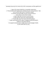
6.4.1 Disassemble front bow cap and instrument (see Fig 10)
• Dismount bolts of bow cap①②, take down front bow cap and disconnect lamp line
• Dismount bolts of support of bow cap③④, disconnect instrument line and take down
instrument and support of bow cap.
6.4.1.1Assembly
• Assemble front damping system according to the inverse disassembly steps and fasten it
with the torque force of 10~12N.m.
Fig 10
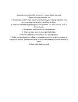
6.4.2 Disassemble headlight and front turn light (see Fig 11)
.Dismount turn light, install nuts and take down turn light
.dismount bolts of support of bow cap② and separate headlight and bow cap①③
.dismount bolts of headlight and separate headlight and bow cap①④

6.4.2.1 Assembly
• Assemble headlight and turn light according to reverse disassembly steps and fasten
them with the torque force of 10~12N.m.
Fig 11
6.4.3 Disassemble front wheel assembly
• Loosen fastening bolts of wheel and axle of lower support of front shock absorber①
• Dismount fastening bolts of front wheel and axle, draw wheels and axles out and
dismount front wheel assembly
• Dismount bolts of front fender and lining② and front fender
6.4.3.1 Assembly
• Assemble front wheel assembly according to the inverse disassembly steps, fasten front wheel and axle
with the torque force of 10~12N.m and bolts with the torque fore of 20-30N.m.
Notice: it is important to fasten fastening bolts of wheel and axle alternatively
and repeatedly in order to disperse loads uniformly. Fastening the second bolt
may make the first bolt loose.
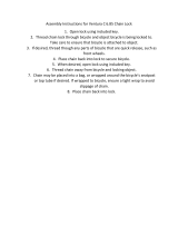
Ensure disk is between brake blocks in assembly of front wheel. Otherwise,
brake lining or disk may be damaged.
Fig 12
6.4.4.Dismount front brake disk (Fig 13, 14)
• place front wheel assembly flatwise with disk upwards. Clean and protect it.
• Dismount bolts of front brake disk①, take down front brake disk② and avoid
contaminating brake disk
6.4.4.1 Assembly
• Assemble front brake disk according to the inverse disassembly steps, use thread lock

glue (Loctite 243) on bolt, fasten it with the torque force of 8-10N.m. Pay attention to
rotation and install direction of brake disk, avoid contaminating brake disk, use absolute
ethyl alcohol in cleaning
• Ensure disk is at a correct position (see the following figure)
13Fig 13 14Fig 14
6.4.5Dismount front shock absorber (see Fig 15)
• Dismount bolts of front brake caliper and take down front brake caliper③
• loosen fastening bolts of front shock absorber of front steering column①, take down
steering limiting gommure of shock absorber②, and take down front left and right shock
absorbers
6.4.5.1Assembly
• Assemble front shock absorber according to the inverse disassembly steps and fasten it
with the torque force of 10~12N.m.
Notice: it is important to fasten bolts of shock absorber alternatively and
repeatedly in order to disperse loads uniformly. Fastening the second bolt can
make the first bolt loose.
Fig 15
6.5 Dismount rear shock absorber and cocket centring (see Fig 16, 17)
Dismount rear shock absorber according to the following steps:

• Put LIGHT BEE on platform or support platwise at bottom bracket area
• Unscrew the bolts of connector at the upper part of shock absorber②: fix rear wheel and
dismount bolts. Put the bicycle on floor.
• Unscrew the bolts of connector at the lower part of shock absorber②
• dismount shock absorber②
• Dismount bolts of cocket centring and take down connecting rod④ of cocket centring⑤
and cocket centring.
6.5.1 Assembly
• Assemble rear shock absorber and cocket centring according to the inverse disassembly
steps. Fasten M8 bolt of shock absorber with the torque force of 25-30N.m.
Don’t damage the paint on cocket centring and bicycle frame in disassembly
and assembly of shock absorber.
Fig 16 17Fig 17
6.6 Disassemble damping spring
Disassemble damping spring according to the following steps:
• Dismount shock absorber (see “dismount rear shock absorber”)
• Unscrew preloaded adjustment nut to loosen spring.
• Dismount gasket of spring seat
• Dismount spring
6.6.1Assembly
• Assemble damping spring according to the inverse disassembly steps.
Fig 18
7.Check, disassemble and assemble head parts

7.1Check the stroke gap of head parts
Fig 15
If head parts have gap or steering position has resistance, check the tightness of bolt① of
cover of head parts. The correct torque is 8-10N.m. Before adjusting the bolt, fasten the
two fastening bolts between handlebar and stand pipe and the fastening bolts on
connecting plate.
• If necessary, fasten or unscrew bolts. If the recommended torque can’t be achieved by
fastening, starlike nuts may be damaged. In the case, you must use new head parts.
• If head parts can’t work normally (resistance in steering, gap or overhigh resistance) after
the recommended torque is achieved by tightening, some parts on bearing may be
damaged. In the case, you must use new head parts.
7.2 Disassemble head parts
Disassemble the head parts of Light Bee according to the following steps:
• Put Light Bee on support at bracket area
• Dismount front bow cap and instrument (see “disassemble front bow cap and instrument).
Don’t damage instrument line.
• Dismount front fender and front wheel (see “dismount front wheel assembly”)
• Dismount brake handle (see “separate brake handle from handlebar”)
• Unscrew locking bolts between handlebar and stand pipe of steering column (see Fig 16).
• Unscrew locking bolts of upper and lower connecting plate of front shock absorber
• Dismount lower connecting plate and shock absorber assembly and ensure no falling
parts
• Dismount bearing cover of hear parts
• Dismount starlike nuts. Install nuts inside stand pipe of steering column through pressure.
Use M6 thread rod to push nuts out from above.
If any part is damaged when drawing out head parts, install new head parts to
ensure the normal operation of system.
Fig 19
7.2.1 Assembly
• Assemble head parts according to the inverse disassembly steps and with the following
torque values:
Important matters: fasten cover of head parts, upper connecting plate and
clamp bolts between handlebar and steering column and locking bolt of shock
absorber of upper connecting plate successively.

• Fasten upper connecting plate and M5 bolt between handlebar and stand pipe of steering
column with the torque of 8N.m.
Locking M16 bolt of front shock absorber: 10-12N.m
Use special tool to pass new starlike nuts through the upper hole of stand pipe of steering
column.
Be careful when inserting starlike nuts. If it is at a deeper position than the
designed depth, locking bolts are not long enough to achieve proper fastening.
Fig 20
8 Disassemble and assemble shifter assembly (Fig 21)
Disassemble head parts of Light Bee according to the following steps:
• Put Light Bee on support at bracket area
• Dismount left and right rearview mirror
• Dismount handle grips, fuler and switch. Don’t damage switch line.
• Dismount upper pump of brake (see “dismount upper pump from handle bar”)
• Dismount locking bolts between handlebar and handlegear tube (see Fig 16), take handle
gear down
8.1.1 Assembly
• Assemble shifter assembly with the following torque and according to the inverse
disassembly steps:
• Fasten main pump of disk brake and M5 bolts between handlebar and handlebar tube
with the torque of 8-19N.m.
Fig 21
9. Check wheel
9.1 Check tire
/