Page is loading ...

Dell EMC S5000
Installation Guide 9.6(0.0)

Notes, Cautions, and Warnings
NOTE: A NOTE indicates important information that helps you make better use of your computer.
CAUTION: A CAUTION indicates either potential damage to hardware or loss of data and tells you how to avoid the
problem.
NOTE: A WARNING indicates a potential for property damage, personal injury, or death.
Copyright © 2014 Dell Inc. All rights reserved. This product is protected by U.S. and international copyright and intellectual property
laws.
Dell
™
and the Dell logo are trademarks of Dell Inc. in the United States and/or other jurisdictions. All other marks and names
mentioned herein may be trademarks of their respective companies.
2014–09
Rev. A00

1 About this Guide...........................................................................................................................5
Related Publications.............................................................................................................................................................. 5
2 Introduction................................................................................................................................ 6
Product Description...............................................................................................................................................................6
3 Unpacking the Switch...................................................................................................................7
Important Points Before You Continue...............................................................................................................................7
Hardware Installation Overview...........................................................................................................................................8
4 Hardware Overview...................................................................................................................... 9
I/O Panel.................................................................................................................................................................................9
Utility Panel........................................................................................................................................................................... 10
Port Numbering Convention...............................................................................................................................................10
System Status....................................................................................................................................................................... 11
5 Site Preparations........................................................................................................................14
Site Selection........................................................................................................................................................................ 14
Cabinet Placement...............................................................................................................................................................14
Storing Components............................................................................................................................................................14
6 Installation................................................................................................................................. 15
Before You Begin................................................................................................................................................................. 15
Installing in a Rack or Cabinet.............................................................................................................................................16
Attaching the Mounting Brackets......................................................................................................................................16
Rack Mounting Safety Considerations.............................................................................................................................. 17
Installing the S5000 Chassis into a 4-Post Rack or Cabinet.......................................................................................... 17
Rack Grounding.................................................................................................................................................................... 18
Important Points to Remember for Installing an Ethernet Module................................................................................18
Installing an Ethernet Module............................................................................................................................................. 19
Replacing an Ethernet Module.......................................................................................................................................... 20
Important Points to Remember for Installing a Fibre Channel Module........................................................................ 20
Installing a Fibre Channel Module.......................................................................................................................................21
Replacing a Fibre-Channel Module....................................................................................................................................22
Important Points to Remember for Installing an AC Power Supply..............................................................................22
Installing an AC Power Supply........................................................................................................................................... 23
Important Points to Remember for Installing a DC Power Supply................................................................................24
Assembling and Connecting the Safety Ground Wire for DC Power Supply.............................................................. 25
Installing a DC Power Supply............................................................................................................................................. 26
Installing the Ferrite Bead for DC Power and Return Cables........................................................................................ 27
Securing Power Cables.......................................................................................................................................................28
Replacing an AC or DC Power Supply.............................................................................................................................. 28
Important Points to Remember for Installing a Fan Module.......................................................................................... 29
Installing a Fan Module....................................................................................................................................................... 29
Contents
Contents 3

Replacing a Fan Module......................................................................................................................................................30
Installing the SFP+ and QSFP+ Optics.............................................................................................................................30
Splitting QSFP+ Ports to SFP+ Ports.............................................................................................................................. 30
Connecting the Stacking Ports (Optional)....................................................................................................................... 31
Connecting Two S5000 Systems..................................................................................................................................... 32
Connecting Three S5000 Systems...................................................................................................................................33
Supplying Power and Powering Up the System..............................................................................................................34
Hot-Swapping Units in a Stack......................................................................................................................................... 35
7 Technical Specifications............................................................................................................. 36
8 Agency Compliance.................................................................................................................... 37
USA Federal Communications Commission (FCC) Statement..................................................................................... 37
Canadian Department of Communication Statement.....................................................................................................37
European Union EMC Directive Conformance Statement.............................................................................................37
Japan: VCCI Compliance for Class A Equipment............................................................................................................ 38
Korean Certification of Compliance.................................................................................................................................. 38
Safety Standards and Compliance Agency Certifications..............................................................................................39
Electromagnetic Compatibility (EMC)..............................................................................................................................39
Product Recycling and Disposal........................................................................................................................................ 39
9 Technical Support.......................................................................................................................41
The iSupport Website.......................................................................................................................................................... 41
Accessing iSupport Services...............................................................................................................................................41
Requesting a Hardware Replacement............................................................................................................................... 41
Contacting Technical Support............................................................................................................................................41
4
Contents

About this Guide
This guide provides site preparation recommendations, and step-by-step procedures for rack mounting, installing and replacing pluggable
modules, and connecting to a power source.
After you have completed the hardware installation and power-up of the S5000, for software configuration information, refer to the Dell
Networking OS Configuration Guide for the S5000 Switch and for Command Line Interface (CLI) information, refer to the Dell
Networking OS Command Line Reference Guide for the S5000 Switch.
CAUTION:
To avoid electrostatic discharge (ESD) damage, wear grounding wrist straps when handling this equipment.
NOTE: Only trained and qualified personnel can install this equipment. Read this guide before you install and power up
this equipment. This equipment contains two power cords. Disconnect both power cords before servicing.
NOTE: This equipment contains optical transceivers, which comply with the limits of Class 1 laser radiation.
NOTE: When no cable is connected, visible and invisible laser radiation may be emitted from the aperture of the optical
transceiver ports. Avoid exposure to laser radiation and do not stare into open apertures.
Topics:
• Related Publications
Related Publications
For more information about the S5000, refer to the following documents:
• Dell Networking OS Configuration Guide for the S5000 Switch
• Dell Networking OS Command Line Reference Guide for the S5000 Switch
• Dell Networking OS Release Notes for the S5000 Switch
NOTE:
For the most recent documentation and software, visit Support :www.dell.com/support .
1
About this Guide 5

Introduction
This document provides basic information about installing the S5000 switch.
For information about how to configure and monitor switch features, refer to the Dell Networking OS Configuration Guide for the S5000
Switch, which is available on the Dell Support website at www.dell.com/support
Topics:
• Product Description
Product Description
This switch is part of Dell EMC S5000 Series of switches for Data Center Top of Rack (ToR) switches.
The S5000 is purpose-built to provide architectural flexibility for unified and virtualized environments. It is a 10G ToR solution that enables
converged local area networks (LAN) and storage area networks (SAN) in the same box. The S5000 delivers Fibre Channel over Ethernet
(FCoE) and Fibre Channel (FC) capability in a one rack unit (RU) ToR switch form factor.
The S5000 supports Data Center Bridging (ETS/PFC/DCBX), FCoE Transit (FIP Snooping), NPIV Proxy Gateway (NPG), and Internet
small computer system interface (iSCSI) storage traffic. The S5000 also provides aggregation and convergence functionality using
pluggable modules for flexible configuration.
2
6 Introduction

Unpacking the Switch
The S5000 and its accessories are shipped in multiple boxes. Before unpacking the switch, inspect the container and immediately report
any evidence of damage. Verify that you have received your ordered items. For example, if you order one S5000 switch, the following
items are included.
NOTE: If any item is missing or damaged, contact your Dell EMC representative or reseller for instructions.
NOTE: Electrostatic discharge (ESD) damage can occur if components are mishandled. Always wear an ESD-preventive
wrist or heel ground strap when handling the S5000 and its components.
• One S5000 switch
• Two Fans
• Two Power Supplies (either AC or DC)
• One rail kit (#1 and #2 Phillips screwdrivers required)
• Screws for rack installation
• Two to Four I/O Modules (according to order)
• Two Blanks
• One RJ-45 to DB-9 female cable
• Two AC or DC power cords for AC or DC units (country/region specific)
• Getting Started Guide
• Safety and Regulatory Information
• Warranty and Support Information
• Software License Agreement
1. Place the container on a clean, flat surface and cut all straps securing the container.
2. Open the container or remove the container top.
3. Carefully remove all components from the container and place it on a secure and clean surface.
4. Remove all packing material.
5. Inspect the switch and accessories for damage.
Topics:
• Important Points Before You Continue
• Hardware Installation Overview
Important Points Before You Continue
• Identify the I/O and Utility panel on the chassis. The I/O panel has four fixed 40GbE ports on the right side of the panel, refer to Figure
1. The Utility panel has the power supply slots, LEDs, and USB slots on the left side of the panel, refer to Figure 3.
• Identify slots 0, 1, 2, and 3 on the I/O panel, refer to Figure 2. You can insert a Fibre Channel module only in slot 0. You can install the
Ethernet modules in slots 0, 1, 2, and 3.
• Identify slots 0, 1, 2, and 3 on the Utility panel, refer to Figure 3. You can insert Power supply units (PSUs) only in slots 0 and 3. You
can insert the Fan modules in any of the slots.
3
Unpacking the Switch 7

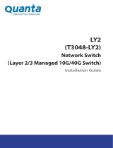
Figure 1. S5000 I/O and Utility Panels
1. I/O panel
2. Utility panel
3. Four 40GbE QSFP+ ports (each port ALSO supports 4 × 10GbE mode)
Hardware Installation Overview
To install the S5000, follow these steps:
1. Attach the mounting brackets.
2. Install the S5000 chassis into a 4–post rack or cabinet.
3. Ground the rack.
4. Install the Ethernet and/or Fibre Channel modules (Fibre Channel module must be installed only in slot 0).
5. Install the power supplies.
6. Secure the power cables.
7. Install the fan modules.
8. Install the SFP+ and QSFP+ optics.
9. Supply power and power up the system.
8
Unpacking the Switch

Hardware Overview
This section contains information about device characteristics and modular hardware configurations for the S5000.
The S5000 has the following physical dimensions:
• Height: 1.71 inches (43.5 mm)
• Width: 17.4 inches (441.9 mm)
• Depth: 28 inches (711.2 mm)
The S5000 has a chassis design with 640Gbps switching bandwidth.
The system also provides one DB9 RS-232 console port with YOST RJ-45 pinout and a dedicated Ethernet service port for out-of-band
(OOB) management functions.
Topics:
• I/O Panel
• Utility Panel
• Port Numbering Convention
• System Status
I/O Panel
All fixed data ports (4 × 40GbE quad small form-factor pluggable plus [QSFP+] ports) and the four slots for pluggable modules are on the
I/O panel.
The I/O panel includes:
• Pluggable Modules
• 12-Port Ethernet Module (1G/10G speeds)
• 12-Port FC/Ethernet Universal Module (2G/4G/8G/10G speeds).
• 4 × 40GbE QSFP+ Ports and light emitting diodes (LEDs)
Figure 2. S5000 I/O Panel
1.
Slot 0 (supports Ethernet and Fibre Channel modules) 2. Slot 1 (supports only Ethernet modules)
3. Slot 2 (supports only Ethernet modules) 4. Slot 3 (supports only Ethernet modules)
5. Four 40GbE QSFP+ ports (each port ALSO supports 4 × 10GbE
mode)
NOTE: The LED displays for the system status are on both sides of the chassis. The fan and power status LEDs are on
the Utility panel.
4
Hardware Overview 9

Utility Panel
The Utility panel side of the platform contains the fan and power modules.
Figure 3. S5000 Power Supplies and Fan Modules
1. Slot 0 (for PSU 0) 2. Slot 1 (for Fan Module 0)
3. Slot 2 (for Fan Module 1) 4. Slot 3 (for PSU 1)
5. Grab Handles
Power Supplies
The S5000 supports two hot-swappable PSUs.
NOTE:
The PSUs must be installed at the customer site.
The S5000 has SKUs that support the following configurations:
• AC PSU with fan airflow from I/O to Utility
• AC-R PSU with fan airflow from Utility to I/O
• DC PSU with fan airflow from I/O to Utility
• DC-R PSU with fan airflow from Utility to I/O
PSUs are field replaceable. To ensure power redundancy and adequate cooling, install two power supplies in the switch. When running
with full redundancy (two PSUs installed and running), you can remove and replace one PSU while the other PSU is running without
disrupting traffic.
Fans
The S5000 supports two fan trays with airflow directions from I/O to Utility or Utility to I/O.
Do not mix I/O to Utility and Utility to I/O airflows in a single S5000 chassis. All fans and PSUs in a configuration must be in the same
airflow direction. If you create a mixed airflow configuration, the software notifies you of the invalid configuration.
The fans must be installed at the customer site.
Port Numbering Convention
Even-numbered ports are at the bottom of the I/O panel and for modules odd-numbered ports are at the top of the I/O panel.
Figure 4. Port Numbering
10
Hardware Overview

The previous figure shows the fixed four 40GbE data ports (ports 48, 52, 56, and 60) and the four slots for pluggable modules on the
S5000 I/ O panel. You can also use the 40GbE ports in 4 × 10GbE mode.
The S5000 supports the following possible modules:
• 12-Port Ethernet Module (1G/10G speeds) (slot 0, 1, 2, or 3)
• 12-Port FC/Ethernet Universal Module (2G/4G/8G/10G speeds).
The valid slot numbers are stack-unit numbers (from 0 to 11). The valid port numbers for each interface type are:
• 1GbE: Ports 0 to 47
• 10GbE: Ports 0 to 63
• 40GbE: Ports 48, 52, 56, and 60
• Fibre Channel: Ports 0 to 11
• Management: Port 0
System Status
You can view S5000 status information in several ways, including LEDs and through the CLI show commands and with simple network
management protocol (SNMP).
For more information about these options, refer to the Dell Networking OS Command Line Reference Guide and Dell Networking OS
Configuration Guide for the S5000 Switch.
As shown in the following figure, the S5000 includes LED displays on the I/O and Utility side of the chassis. When the S5000 powers up
or reloads, the status LED on the power supplies are solid green. The following table lists the LED definitions for the S5000 system.
Figure 5. System LEDs (Utility Panel) (AC Power Supplies installed)
1.
Locator beacon LED 2. Alarm LED
3. System status LED 4. Master LED
5. Seven–segment display to identify Stack ID 6. PSU status LED
7. Fan status LED
NOTE: For AC PSUs, an illuminated translucent handle indicates the power status.
NOTE: For DC PSUs, the power status LED is on the upper-left corner.
Figure 6. System LEDs (I/O Panel)
1. Locator beacon LED
2. Alarm LED
Hardware Overview
11

3. System status LED
Table 1. System LED Displays (Utility and I/O Panel)
Label LED Color/Display Description
Locator beacon LED
• Off
• Blue
• No activity
• System beacon/locator
Alarm LED
• Off
• Amber solid
• Red solid
• No alarm
• Minor alarm
• Critical alarm
System status LED
• Off
• Green solid
• Green blinking
• Amber solid
• No power
• Normal operation
• System is booting
• System in card problem state
Master LED
• Green solid
• Green blinking
• Off
• Switch in Stacking Master mode OR
Switch in Standalone mode
• Switch in Stacking Standby mode
• Switch in Stacking Member mode
PSU status LED
• Green solid
• Off
• Normal operation
• Power not present
Fan status LED
• Green solid
• Off
• Normal operation
• Power not present
Figure 7. Module LEDs
1.
Port locator beacon LED 2. Port link/activity LED
3. Module locator beacon LED 4. Module status LED
NOTE: The downward and upward pointing triangles denote the lower and upper port LEDs respectively.
Table 2. Ethernet Port/Module LEDs
Label LED Color/Display Description
Port locator beacon LED
• Off
• Blue
• No activity
• Port beacon/locator
Port link/activity LED
• Off • No link or interface disabled
12 Hardware Overview

Label LED Color/Display Description
• Green solid
• Green blinking
• Link present and interface enabled
(Ethernet module)
• Port has activity
Module locator beacon LED
• Off
• Blue
• No activity
• Module beacon/locator
Module status LED
• Off
• Green solid
• Yellow
• Module is not powered up
• Module is powered up
• Problem detected with module
Table 3. Fibre Channel Port/Module LEDs
Label LED Color/Display Description
Port locator beacon LED
• Off
• Blue
• Green
• No activity
• Port beacon/locator
• Fibre Channel mode enabled
Port link/activity LED
• Off
• Green solid
• Green blinking
• No link or interface disabled
• Link present and interface enabled
• Port has activity
Module locator beacon LED
• Off
• Green
• No activity
• Module beacon/locator
Module status LED
• Off
• Green solid
• Yellow
• Module is not powered up
• Module is powered up
• Problem detected with module
Figure 8. QSFP+ Port LEDs
1. Port link/activity LED
Table 4. 40GbE Port/Module LEDs
Label LED Color/Display Description
Port link/activity LED
• Off
• Green solid
• Green blinking
• No link or interface disabled
• Link present and interface enabled
• Port has activity
Hardware Overview 13

Site Preparations
The S5000 is suitable for installation as part of a Common Bond Network (CBN). It can be installed in:
• network telecommunication facilities
• data centers
• other locations where the National Electric Code (NEC) applies
Topics:
• Site Selection
• Cabinet Placement
• Storing Components
Site Selection
Dell EMC equipment is intended for installation in restricted access areas. A restricted access area can only be accessed by service
personnel by using a special tool, lock, key or other means of security and access is controlled by the authority responsible for the location.
Ensure that the area where you install your S5000 system meets the following safety requirements:
• Near an adequate power source. Connect the system to the appropriate branch circuit protection as defined by your local electrical
codes.
• Environmental temperature between 32° to 104°F (0° to 40°C).
• Relative humidity that does not exceed 85 percent noncondensing.
• In a dry, clean, well-ventilated and temperature-controlled room, away from heat sources such as hot air vents or direct sunlight.
• Away from sources of severe electromagnetic noise.
• Positioned in a rack or cabinet, or on a desktop with adequate space in the front, rear, and sides of the S5000 for proper ventilation
and access.
Cabinet Placement
Install the S5000 only in indoor cabinets designed for use in a controlled environment as described in Site Selection.
The cabinet must meet the following criteria:
• Minimum cabinet size and airflow are according to the Electronic Industries Alliance (EIA) standard.
Storing Components
If you do not install your S5000 and components immediately, Dell EMC recommends properly storing the system and all optional
components until you are ready to install them.
NOTE:
ESD damage can occur when components are mishandled. Always wear an ESD-preventive wrist or heel ground
strap when handling the S5000 and its accessories. After you remove the original packaging, place the S5000 and its
components on an anti-static surface.
1. Storage temperature must remain constant ranging from -4° to 158° F (-20°C to 70° C).
2. Store on a dry surface or floor, away from direct sunlight, heat, and air conditioning ducts.
3. Store in a dust-free environment.
5
14 Site Preparations

Installation
Topics:
• Before You Begin
• Installing in a Rack or Cabinet
• Attaching the Mounting Brackets
• Rack Mounting Safety Considerations
• Installing the S5000 Chassis into a 4-Post Rack or Cabinet
• Rack Grounding
• Important Points to Remember for Installing an Ethernet Module
• Installing an Ethernet Module
• Replacing an Ethernet Module
• Important Points to Remember for Installing a Fibre Channel Module
• Installing a Fibre Channel Module
• Replacing a Fibre-Channel Module
• Important Points to Remember for Installing an AC Power Supply
• Installing an AC Power Supply
• Important Points to Remember for Installing a DC Power Supply
• Assembling and Connecting the Safety Ground Wire for DC Power Supply
• Installing a DC Power Supply
• Installing the Ferrite Bead for DC Power and Return Cables
• Securing Power Cables
• Replacing an AC or DC Power Supply
• Important Points to Remember for Installing a Fan Module
• Installing a Fan Module
• Replacing a Fan Module
• Installing the SFP+ and QSFP+ Optics
• Splitting QSFP+ Ports to SFP+ Ports
• Connecting the Stacking Ports (Optional)
• Connecting Two S5000 Systems
• Connecting Three S5000 Systems
• Supplying Power and Powering Up the System
• Hot-Swapping Units in a Stack
Before You Begin
Before installing the switch, verify that you meet these guidelines:
• Enough clearance to the front of the switch so you can read the LEDs.
• AC/DC power cord reaches from the power outlet to the Utility-panel connector.
• Switch is rack-mounted before you install the power supply modules.
• Cabling is away from sources of electrical noise, such as radios, power lines, and fluorescent lighting. Make sure that the cabling is
safely away from other devices that might damage the cables. If needed, allow one rack unit (RU) space between devices to provide
room for cabling.
• Airflow around the switch and through the vents is unrestricted.
• Temperature around the unit does not exceed 104°F (40°C). If the switch is in a closed or multirack assembly, the temperature might
be higher than normal room temperature.
• Humidity around the switch does not exceed 85 percent.
• Altitude at the installation site is below 6600 feet.
6
Installation 15

• Switch is installed in an environment as free as possible from dust and foreign conductive material (such as metal flakes from
construction activities). Cooling mechanisms, such as fans and blowers in the switch, can draw dust and other particles causing
contaminant buildup inside the chassis, which can result in system malfunction.
Installing in a Rack or Cabinet
To install the S5000 system, Dell EMC recommends
completing the installation procedures in the order
presented here.
NOTE: Always handle the system and its components with care. Avoid dropping the S5000 chassis or its field
replaceable units.
NOTE: For proper ventilation, position the S5000 chassis in an equipment rack (or cabinet) with a minimum of 5 inches
(12.7 cm) of clearance around exhaust vents. The acceptable ambient temperature ranges are listed in the
Environmental Parameters
section.
CAUTION: Always wear an ESD-preventive wrist or heel ground strap when handling the S5000 and its components. As
with all electrical devices of this type, take all necessary safety precautions to prevent injury when installing this
system. ESD damage can occur if components are mishandled.
Attaching the Mounting Brackets
The S5000 is shipped with mounting brackets (rack ears) and the required screws (eight screws) for rack or cabinet installation. The
brackets are enclosed in a package with the chassis.
1. Take the brackets and screws out of their packaging.
2. Slide the mounting brackets, as shown in the following figure.
Figure 9. Slide the mounting brackets
a. Utility side of the chassis
b. Mounting Bracket
c. Holding Bracket (factory installed)
16
Installation

Rack Mounting Safety Considerations
You may either place the switch on the rack shelf or mount the switch directly into a 19" wide, EIA-310-E- compliant rack.
• Rack loading — Overloading or uneven loading of racks may result in shelf or rack failure, which may damage equipment and cause
possible personal injury. Stabilize racks in a permanent location before loading begins. Mount the components beginning at the bottom
of the rack, then work to the top. Do not exceed your rack load rating.
• Power considerations — Connect only to the power source specified on the unit. When multiple electrical components are installed in
a rack, ensure that the total component power ratings do not exceed the circuit capabilities. Overloaded power sources and extension
cords present fire and shock hazards.
• Elevated ambient temperature — If installed in a closed rack assembly, the operating temperature of the rack environment may be
greater than the room ambient temperature. Use care not to exceed the 40°C maximum ambient temperature of the switch.
• Reduced air flow — Install the equipment in the rack so that the amount of airflow required for safe operation of the equipment is not
compromised.
• Reverse air flow — Necessary clearance is required to ensure cool air intake and to avoid hot air blow out from I/O panel.
• Reliable earthing — Maintain reliable earthing of rack-mounted equipment. Pay particular attention to the supply connections other
than the direct connections to the branch circuit; for example, use of power strips.
• Do not mount the equipment with the Utility panel facing in the downward position.
NOTE: These instructions are a condensed reference. Read the safety instructions in your Safety, Environmental, and
Regulatory information booklet before you begin.
NOTE: The illustrations in this document are not intended to represent a specific switch.
Installing the S5000 Chassis into a 4-Post Rack or
Cabinet
NOTE:
Dell EMC recommends that one person hold the S5000 chassis in place while a second person attaches the
brackets to the posts.
Attach the bracket "ears" to the rack or cabinet posts, using two screws for each bracket. Ensure the screws are tightened firmly.
Figure 10. Front Rack Installation
a. Screws
b. 4–Post Rack or Cabinet
c. Mounting Bracket
Installation
17

Rack Grounding
When you prepare your equipment rack, ensure that the rack is earth ground. You must ground the equipment rack to the same ground
point the power service uses in your area. The ground path must be permanent.
Important Points to Remember for Installing an
Ethernet Module
• Installing and swapping of Ethernet modules must be done BEFORE power up. If you need to install or replace a module, power down
the system before you install or replace it. If you install or replace a module when the system is powered up, the system does not
recognize the module. Online insertion of modules can result in a catastrophic failure.
• Although the handle and port numbering may appear differently on an Ethernet module, there is no functional difference. A module
may have:
• A larger handle that covers the entire front of the module and has the part number written on top of the handle. Port numbering is
written on the front of the handle.
• A smaller handle that is half the size and does not cover the release button. The part number is written on the front of the handle.
Port numbering is written on the lower part of the front of the module.
NOTE: Electrostatic discharge (ESD) damage can occur if components are mishandled. Always wear an ESD-preventive
wrist or heel ground strap when handling the S5000 and its components.
NOTE: For the Ethernet module, the part name and port number are inscribed on the handle, as shown in the following
figure:
NOTE: A blue color release latch indicates that the Ethernet module does not support hot swapping during switch
operations. Instead, you must power down the switch before removing and replacing an Ethernet module. A red color
release latch indicates that the Ethernet module supports hot swapping during switch operations.
18 Installation

Figure 11. Part name and Port number on the Ethernet Module Handle
1. Part Name
2. Port Number
Installing an Ethernet Module
1. Use the grab handle on the Ethernet module to slide it into the switch module slot.
2. Connect any network interface cables to the attached module.
Installation
19

Figure 12. Installing an Ethernet Module
1. Release latch
2. Ethernet Module
Replacing an Ethernet Module
NOTE:
S5000 does not support the hot swapping of an Ethernet pluggable module during switch operations. Instead,
you must power down the switch before removing and replacing an expansion module.
1. Disconnect any network interface cables attached to the module.
2. Use the grab handle to slide the Ethernet module out of the switch module slot.
3. Use the grab handle on the replacement Ethernet module to slide it into the switch module slot.
4. Connect any network interface cables to the attached module.
Important Points to Remember for Installing a
Fibre Channel Module
• You must insert the Fibre Channel module only in slot 0. If you use an FC module on an S5000 switch, the device cannot be stacked.
• If you want to use the FC module in passthrough Ethernet mode, use the stack-unit unit-number port-group number
portmode ethernet command in Configuration mode.
• Installing and swapping of Fibre Channel modules must be done BEFORE power up. If you need to install or replace a module, power
down the system before you install or replace it. If you install or replace a module when the system is powered up, the system does not
recognize the module. Online insertion of modules can result in a catastrophic failure.
• The S5000 does not support the hot swapping of a Fibre Channel pluggable module during switch operations. Instead, you must
power down the switch before removing and replacing a Fibre Channel module.
• Although the handle and port numbering may appear differently on a Fibre Channel module, there is no functional difference. A module
may have:
• A larger handle that covers the entire front of the module and has the part number written on top of the handle. Port numbering is
written on the front of the handle.
• A smaller handle that is half the size and does not cover the release button. The part number is written on the front of the handle.
Port numbering is written on the lower part of the front of the module.
NOTE:
Electrostatic discharge (ESD) damage can occur if components are mishandled. Always wear an ESD-preventive
wrist or heel ground strap when handling the S5000 and its components.
NOTE: The part name and port number of a Fibre Channel module are inscribed on the handle as shown below.
20 Installation
/