Page is loading ...

ICR
Institutional Commercial Remote
For Use with Hunter Controllers
Owner’s Manual and
Installation Instructions
ENGLISH/ESPAÑOL
®
ICR
®
OFF ON
MODE

TABLE OF CONTENTS .....................................................................................
Introduction .................................................................................................................................................................. 1
ICR Components
........................................................................................................................................................... 2
SmartPort
®
Wiring Harness ............................................................................................................................................ 4
Installing the SmartPort
®
Wiring Harness ....................................................................................................................... 4
Wiring the SmartPort
®
to Hunter Controllers................................................................................................................... 5
Typical Installations
....................................................................................................................................................... 6
Preparing the Transmitter for Use
................................................................................................................................... 6
Installing the Transmitter Battery
................................................................................................................................... 7
Changing the Run Time
.................................................................................................................................................. 7
Changing the Transmitter Address
.................................................................................................................................. 8
Changing the Maximum Station Number
......................................................................................................................... 8
Preparing the Receiver for Use
....................................................................................................................................... 9
Changing the Receiver Address
...................................................................................................................................... 9
Activating a Station with the ICR
.................................................................................................................................. 10
Maximizing Operating Range
........................................................................................................................................ 11
Troubleshooting Guide
................................................................................................................................................. 12
Specifications .............................................................................................................................................................. 13

1
INTRODUCTION ...............................................................................................
Finally there’s an affordable remote control system designed with the commercial irrigation contractor in mind. Hunter is
pleased to introduce the Institutional Commercial Remote (ICR). This rugged remote design offers similar functionality as
our SRR remote, but with longer range capability.
With the ICR there’s no need to walk back and forth to the controller to conduct manual watering operations when doing
maintenance or repair work on your irrigation systems. Also, winterization can be done quickly and easily with one worker
instead of two.
The ICR is designed to be rugged, and water resistant. Its large LCD display and push button design makes it easy to
operate. Best of all, with an operating range from ½ to 1 mile, you’ll be able to conduct remote operations on even the
largest irrigation systems.
The following instructions provide information on installing, setting up, and operating your ICR.

2
ICR COMPONENTS .............................................................................................
ICR
OFF ON
MODE
®
A
2
3
4
1
B D
C
5
7
8
6
9

3
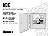
B – Receiver
7. Receiver Body – Rugged, water resistant design.
8.
Addressing Button – Allows for easy receiver to
transmitter addressing.
9.
External Antennae – Flexible, removable antennae
for maximum range.
C – SmartPort
®
D – Carrying Case
This section will provide a brief overview of some of the
components on the ICR. Each item will be discussed in
further detail later, however, this section can be helpful in
getting acquainted with the different options available.
A – Transmitter
1. Transmitter Body – The ICR transmitter is designed to
be dirt tolerant and water resistant.
2.
LCD Display – Large, easy to read LCD display.
3.
Control Buttons – Push button operation.
4.
External Antennae – Flexible, removable rubber for
maximum radio range.
5.
Battery Compartment – The ICR is designed to operate
on a four AA alkaline batteries. The batteries easily drop
into a battery holder.
6.
Belt Clip – Belt clip provides convenient access to the
transmitter at all times.
ICR
OFF ON
MODE
®
A
2
3
4
1
B D
C
5
7
8
6
9

4
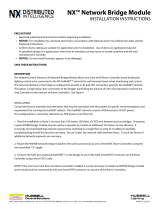
To utilize the ICR remote control system, your controller
must be equipped with a SmartPort wiring harness. This
wiring harness provides the communication port where the
ICR receiver is attached. The SmartPort can be connected to
Hunter SRC, Pro-C and ICC controllers. A SmartPort wiring
harness is provided with your ICR remote system. The
typical SmartPort location is approximately 12" below the
controller. The recommended installation procedure for this
location would be as follows:
SmartPort
®
WIRING HARNESS .......................................................................
INSTALLING THE SmartPort
WIRING HARNESS ........................................
1. Install a ½" female threaded “Tee” in the field wiring
conduit approximately 12" below the controller.
2. Feed the red, white, and blue wires of the SmartPort
through the base of the “Tee” and into the controller
wiring compartment as shown in the following figures.
NOTE: The harness may be installed outdoors
by bringing the conduit through an exterior
wall, then installing the appropriate fitting.
NOTE: For installations where the receiver
will be installed permanently on an outside
wall, make certain that the SmartPort is the
version with an o-ring seal.
1
/2" Thread
To Controller
Pre-assembled Assembled

5
SRC Controller SmartPort Installation
Access the terminal strip area and attach the red wire to the
left
AC screw slot, attach the white wire to the next AC screw
slot and attach the blue wire to the screw slot marked “
R”.
Pro-C Controller
SmartPort Installation
Access the terminal strip area on the
main module and attach the red wire to
the bottom most
AC screw slot, attach
the white wire to the upper
AC screw
slot and attach the blue wire to the
screw slot marked “
REM”.
ICC Controller SmartPort Installation
Access the terminal
strip area on the power
module and attach the
red wire to the bottom
most
AC screw slot,
attach the white wire
to the upper
AC screw
slot and attach the blue
wire to the screw slot
marked “
REM”.
WIRING THE SmartPort
®
TO HUNTER CONTROLLERS ..............................
NOTE: Hunter ACC controllers are provided
with the SmartPort
®
Factory installed.
Red
Blue
White
Blue
White
Red
AC AC R RS C MV 1 2 3 4 5 6
White
Blue
Red

6
Although the ICR Receiver is water
resistant, it is recommended that the
SmartPort
®
connector and Receiver be
mounted indoors if it is to be left per
-
manently mounted to the controller.
TYPICAL INSTALLATIONS ................................................................................
The ICR remote system is designed to work right out of
the box. This means that other than installing the battery,
you may choose to skip this entire section. However, we
recommend that you read it so that you can customize your
ICR to add functionality and security to your system.
PREPARING THE TRANSMITTER FOR USE .................................................
Controller
Receiver
Outdoor Installation
(Temporary Connection
of Receiver Only)
Indoor Installation

7
The ICR transmitter requires 4 AA alkaline batteries. To
install the batteries. remove the two screws holding the
battery on the back of the transmitter. Drop the batteries
into the battery compartment and replace the door. Your
transmitter is now ready to operate.
with the current Run Time is displayed. (default is 10
minutes) The Run Time will be blinking at this point.
If more than 5 seconds go by
without a button being pressed,
the Transmitter will revert back to
displaying the active station.
3. Use the
or buttons to
change the Run Time to any of
the 8 settings ranging from 1 to
90 minutes. Then do not touch any of the buttons for
5 seconds and the display will stop blinking and return
back to the active station.
INSTALLING THE TRANSMITTER BATTERIES ............................................
CHANGING THE RUN TIME ..............................................................................
You have the ability to adjust the amount of time that a
station will run once it has been turned on by your ICR.
This does not affect the run time programmed into your
controller. This adjustment is made at the transmitter as
described below.
To change the Run Time:
1. If the unit is OFF (no display), power the transmitter by
pressing any of the buttons for at least 1 second then
releasing the button. The transmitter will illuminate and
display the active station.
2. Press the Mode button until the words “Run Time” along
36/5*.&

8
Both the ICR Transmitter and Receiver have an “address”
that they use when communicating. If the addresses do
not match, the Receiver will ignore the transmission. Your
ICR comes from the factory with both the transmitter and
Receiver address set to 0. You may change the address to
any value from 0-127 for added security. Note that if you
change the Transmitter address, the Receiver must “learn”
the new address as described in the “Preparing the Receiver
for Use” section.
To change the Transmitter address:
1. If the unit is OFF (no display), power the Transmitter up
by pressing any of the buttons for at least 1 second then
releasing the button. The Transmitter will illuminate the
active station.
2. Press the Mode button until the word “Address” appears
on the display. The address will be blinking at this point.
If more than 5 seconds go by
without a button being pressed,
the Transmitter will revert back to
displaying the active station.
3. Use the
or button to
change the address to any value
between 0 and 127. Then do not
touch any of the buttons for 5 seconds and the display
will stop blinking and return back to the active station.
Your ICR Transmitter comes from the factory with the
maximum number of stations set to 9. This means that when
you use the
or buttons to change the station, you
may change it to any number between 1 and 9. However, if
you have controllers with more than 9 stations you will want
to increase the maximum number of stations.
CHANGING THE TRANSMITTER ADDRESS ..................................................
To change the Maximum Number of Stations:
1. If the unit is OFF (no display), power the Transmitter up
by pressing any of the buttons for at least 1 second then
releasing the button. The Transmitter will illuminate the
active station.
CHANGING THE MAXIMUM NUMBER OF STATIONS .................................
"%%3&44

9
2. Press the Mode button until the
word “Max Station” appears
on the display. The maximum
number of stations will be
blinking at this point.
3. Use the
or button
to increase or decrease the
maximum number of stations. Then do not touch any
of the buttons for 5 seconds and the display will stop
blinking and return back to the active station.
The ICR is designed to operate with two groups of Hunter
controllers:
SRC/Pro-C/ICC Controllers
The maximum number of stations from 1 to 48. The ICR also
provides the user with the ability to operate programs
(A, B, C).
ACC/ACC Decoder Controllers
Selecting the maximum station number 240 allows the user
to operate up to 240 stations and 18 programs (programs
are displayed with a P and program number ex: P5).
PREPARING THE RECEIVER FOR USE ............................................................
As stated earlier, your ICR is designed to work right out of
the box. If you have decided to change your Transmitter
address as described in the previous section, you must allow
the Receiver to “learn” this new address. Once learned, the
only way to remove the address from the Receiver memory
is to learn a different address. This can be done by following
the simple steps outlined below.
Changing the Receiver Address
1. Hold down the single button on the face of the
Receiver while you are plugging it into an active
SmartPort
®
wiring harness (one connected to a
powered controller). When this is done the
Receiver will beep 4 times.
NOTE: When the ICR transmitter is set in
the ACC mode (240 stations), the ICR will
only communicate with ACC controllers. To
operate other Hunter controllers (SRC, Pro-C,
and ICC) with your remote, the transmitter
max stations needs to be set to a number from
1 to 48 stations.
."945"5*0/

10
To remotely activate a station or program:
1. Plug your Receiver into an active SmartPort
®
wiring
harness (one attached to a powered controller) and wait
for 2 beeps indicating the Receiver is ready.
2. If your Transmitter is not on (no display), press any
button for at least 1 second and release. The Transmitter
will display the active station.
3. Use the
or buttons to display the station or
program (A,B, or C) you would
like to start.
4. Momentarily press the “ON”
button to start the station or
program. The Transmitter will
display the word “TRANSMIT”
and will flash for about 4 seconds indicating that it is
sending the command to the Receiver. If you are near the
Receiver, you will hear it beep 2 times, indicating that it
has received the command.
5. Press the “OFF” button at any time to turn off the station
or program. The display will again read “TRANSMIT” and
flash, and the Receiver will again beep twice. The ICR
is designed to turn one station on at a time. Therefore,
turning a station on while another is already on will
cause the first station to turn off.
6. If one of the programs (A,B, C or P1 through P18)
is selected, all stations in the selected program will
run sequentially for the run time programmed in the
controller.
ACTIVATING A STATION WITH THE ICR REMOTE SYSTEM ......................
2. After the Receiver starts to beep, release the button.
3. Press either the “ON” or “OFF” button on your transmit
-
ter.
4. The Receiver will beep 4 additional times indicating
that it has learned the new Transmitter address and will
respond only to it from this point on.
The ICR system will allow you to remotely turn on and off
any station on your Hunter controller with the press of a
button. Once on, the station will run for the run time you
have designated in the ICR transmitter.
45"5*0/

11
NOTE: The ICR remote can activate any station
on the controller whether the controller dial
is in the “System Off”, “Run” or “Run/Bypass
Sensor” modes. If a sensor device has been
wired to the controller, the ICR will not
override the sensor for manual operation.
The ICR is designed as an extended range remote that
should meet the range requirements for even the largest
irrigation systems. The maximum range of transmission will
vary from approximately ½ mile to 2 miles depending upon
the site terrain and the location of the Receiver.
Listed below are a few steps to assure that you are
getting the maximum range possible:
1. Do not install the SmartPort
®
wiring harness (that the
Receiver connects to) near large sources of metal such
as power meters, water pipes, and metal siding.
2. Do not install the SmartPort wiring harness in a
basement or underground location.
3. For maximum range in all directions from the Receiver,
the Receiver antennae should be pointed straight up
(vertically). If the Receiver is mounted with its antennae
oriented horizontally, reception will be very good if the
Transmitter is on either side of the antennae, but poor if
it is facing the end of the antennae.
4. When operating the Transmitter, hold the Transmitter as
vertical as possible and turn and face the direction of the
Receiver even though it may be a long way away.
MAXIMIZING OPERATING RANGE .................................................................

12
TROUBLESHOOTING GUIDE .............................................................................
PROBLEM CAUSES SOLUTIONS
Transmitter is blank. Transmitter is Off.
Battery is dead.
Press any button for 1 second.
Replace battery.
Can’t access all the desired stations
on the transmitter.
Maximum station number is
set wrong.
See “Setting the Maximum Station stations Number”
Receiver doesn’t beep two times
after plugging it into the SmartPort
®
.
SmartPort is not connected properly.
Controller has no power.
Recheck the SmartPort installation.
Check controller power.
Receiver beeps twice after plugging
it in, but won’t respond to the
transmitter.
Receiver and Transmitter addresses
don’t match.
Relearn address at Receiver.
Transmitter display stays on. Transmitter will turn off
automatically.
Wait approximately 2 minutes without pressing any
buttons. Transmitter will “fall asleep.”

13
SPECIFICATIONS ................................................................................................
Operating Specifications
• Address Range: 0-127
• Maximum stations supported: 240
• Run Time: 8 settings from 1 to 30 minutes
• Range: up to 2 miles depending upon time terrain
Electrical Specifications
• Power Source Transmitter: 4 AA alkaline batteries
• Power Source Receiver: 24VAC, 0.050 amps
• System Operating Frequency: 27MHz band
Default Settings
Address = 0 (may be varied from 0-127)
Number of Stations = 9 (may be varied from 1-48)
Run Time: 10 minutes
Dimensions
Transmitter (w/o antennae): Height: 6.5"
Width: 3.25"
Depth: 1.25"
Receiver (w/o antennae): Height: 6.25"
Width: 3"
Depth: 1.25"
/