
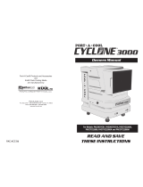
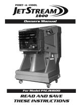
Owners Manual
READ AND SAVE
THESE INSTRUCTIONS
Port-A-Cool, LLC
P.O. Box 2167 • 709 Southview Circle • Center, TX 75935
Phone 936-598-5651 • 800-695-2942
www.port-a-coolllc.com
Port-A-Cool® Products and Accessories
and
KÜÜL® Pads Cooling Media
are manufactured by
PAC-ACC-03 04132011
®
Includes
Port-A-Cool Cyclone
™
Port-A-Cool JetStream
™

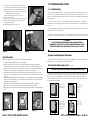
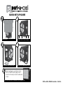
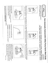
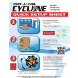
QUICK SET UP GUIDE
®
Remove box
Position unit on level surface
Fill sump or attach water hose Plug unit into appropriate outlet
Fill the tank then turn on the pump switch and the fan.
Pads should appear wet before starting
the fan. Check the water gauge (see in-
structions for setup) to monitor water level
in tank.
PORT-A-COOL OWNER’S MANUAL • PAGE 36

PORT-A-COOL®
Evaporative Cooling Unit
OWNERS MANUAL
READ AND SAVE THESE INSTRUCTIONS
CONTENTS:
I. SAFE OPERATION .............................................................................. page 1
II. SETUP .......................................................................................... page 1
A. Unpacking the PORT-A-COOL® unit
B. Connecting the water and electricity
III. OPERATING PROCEDURES ............................................................ page 2-3
A. Specifications.
B. Placement of the PORT-A-COOL® unit.
C. Filling with water.
D. Starting the pump and adjusting the water flow.
E. Starting the fan.
IV. MAINTENANCE & STORAGE .......................................................... page 4
A. Daily Maintenance
B. Weekly Maintenance
C. Storage
D. Technical Support
V. REPLACEMENT PARTS ...................................................................... page 5
A. RMA Procedures
B. PORT-A-COOL® unit Limited Warranty
C. Fan and Pump Replacement ..........................................page 6-8
D. Exploded Views and Parts lists by model .................page 9-19
VI. WIRING DIAGRAMS ..................................................................page 20-23
VII. UNIT OPERATION WARNINGS & OVERVIEWS ............................... page 24-27
VIII. TROUBLESHOOTING ...............................................................page 28-32
IX. FREQUENTLY ASKED QUESTIONS ..........................................page 33-34
FOR ELECTRIC MODELS
PAC2K482S, PAC2K361S, PAC2K363S, PAC2K36HPVS, PAC2K24HPVS, PAC2K16HPVS, PAC2K163SHD, PAC163SVT,
PACJS1600, PACJS2400, PAC2KCYC01, PAC2KCYC01A, PACCYC02, PACCYC02A
INCLUDES ExPORT MODELS
PACCYC22050, PACCYC22060, PACCYC22050A, PACCYC22060A, PACJS160022050, PACJS160022060, PACJS240022050,
PACJS240022060, PAC161SVT22050, PAC161SVT22060, PAC16HPFC-22050, PAC16HPFC-22060, PAC2K161FC22050,
PAC2K161FC22060, PAC2K161S-22050, PAC2K161S-22060, PAC2K16HP-22050, PAC2K16HP-22060, PAC2K24HP220-50,
PAC2K24HP220-60, PAC2K362S220-50, PAC2K36HP220-50, PAC2K36HP220-60, PAC2K481S220-50, PAC2K481S220-60
PAGE 35 • PORT-A-COOL OWNER’S MANUAL
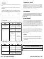
Q. WHAT IS THE AMOUNT OF MOISTURE PRODUCED BY A UNIT?
A. Approximately 2% to 5% increase in humidity is produced depending on
the temperature and humidity of the environment. This amount of increase in
humidity is not noticeable in a ventilated area where the air produced by the
unit is exhausted.
Q. HOW LONG WILL THE WATER SUPPLY LAST IN THE SUMP TANK?
A. With no direct water source available, the unit will evaporate the water in a
filled sump tank within two to eight hours of operation, depending on model
and reservoir size. Also, the evaporation rate will vary depending on tempera-
ture and humidity. A water source for refilling the sump tank is recommended
by the manufacturer. Most units have an internal float valve for regulating water
flow into the sump.
Q. SHOULD I USE ICE IN THE SUMP TANK FOR BETTER COOLING?
A. Some of the vapor from the ice water may be picked up and distributed by
the fan, but this does not increase evaporation and therefore will not produce
significant cooling.
Q. WHERE ARE THE MODEL AND SERIAL NUMBERS FOUND ON THE UNIT?
A. On the outside of the housing of every unit is a metal plate with a white
label with printed barcodes and other information. Unit model numbers begin
with the letters “PAC.” Serial numbers are all-digit numbers. Please always
provide the unit’s serial number and model number when contacting Parts/
Technical Support.
Q. WHAT IF MY QUESTIONS AREN’T ANSWERED HERE?
A: Tech Support staff is available 8 a.m. to 5 p.m. Central Time, Monday
though Friday at 1-888-COOL-AID or by e-mail at [email protected].
FREQUENTLY ASKED QUESTIONS (continued)

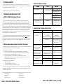
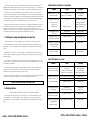
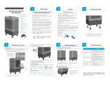
I. SAFE OPERATION - READ BEFORE PROCEEDING
II. SETUP
A. Unpacking the PORT-A-COOL® unit.
PORT-A-COOL® units are shipped completely assembled. The PAC2K482S, PAC2K361S, PAC2K363S,
PAC2K36HPVS, PAC2K24HPVS, PAC3SVT, PACJS1600, PACJS2400, PAC2KCYC01 and PAC2KCYC01A
models ship on a plastic pallet with a cover box strapped over the unit. Cut the straps and remove the
box by lifting it over the unit. Remove the protective plastic dust cover and lift the unit off the pallet.
Models PAC2K163SHD, PAC2K16HPVS, PACCYC02 and PACCYC02A are shipped in an enclosed
corrugated box. Remove from box to unpack.
B. Connecting the water and electricity.
Water Connection
PORT-A-COOL® UNIT MUST BE IN UPRIGHT AND LEVEL POSITION
PAGE 1 • PORT-A-COOL OWNER’S MANUAL
PORT-A-COOL OWNER’S MANUAL • PAGE 34
FREQUENTLY ASKED QUESTIONS (continued)
Q. WHAT IS THE BEST ENVIRONMENT FOR THE PORT-A-COOL® UNIT TO
PRODUCE THE MOST COOL AIR?
A: For optimum performance, the temperature should be 85 degrees F or higher
and the relative humidity should be below 75%. However, PORT-A-COOL® units
will reduce the temperature in almost any environment, making it more pleasant.
Q. WHAT IS THE DIFFERENCE BETWEEN EVAPORATIVE COOLING AND
MISTING SYSTEMS?
A: Misting units spray a shower of water into the air that will collect on people,
objects, equipment, floors, etc. The PORT-A-COOL® unit uses the process of
evaporative to produce cooler air, but does not discharge a mist.
Q. SHOULD I OIL THE FAN MOTOR?
A. The Motor Installation and Maintenance Information manual states, “Sleeve
bearing motors require periodic re-oiling. Re-oil continuous duty units once a
year, intermittent duty units every two years, and occasional duty units every five
years with 30 to 35 drops of SAE no. 20 non-detergent or electric motor oil.”
Q. WHERE CAN I BUY REPLACEMENT PARTS?
A. Unit replacement parts may be purchased from any PORT-A-COOL® product
distributor or directly from PORT-A-COOL® Parts/Technical Support department.
You may also visit www.port-a-coolparts.com to order online.
Q. HOW OFTEN DO PADS HAVE TO BE REPLACED?
A: Depending on the quality of maintenance and frequency of use, pads typically
last up to five years. However, should you have any questions about the life of
the pads for your unit, please call our tech support department for more detailed
information about replacing your pads.
(Continued on next page)
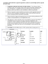
TO REDUCE THE RISK OF ELECTRIC SHOCK, FIRE OR INJURY
• Donotoperateanyfanwithadamagedcordorplug.Discardfanorreturnto
anauthorizedservicefacilityforexaminationand/orrepair.
• Donotruncordundercarpeting,orcovercordwiththrowrugs,runners,or
similarcoverings.Arrangecordawayfromtrafcareatopreventtripping.
• Readinstructionsandlabelscarefully.
• Alwaysunplugelectriccordbeforeworkingontheunit.
• Plugonlyintothree-pronggroundedGFCIprotectedelectricalreceptacle.
• Donotoperateifthereisanydamagetotheplugorcord.
• Donotsteponorrolloverpowercordwithheavyorsharpobjects.
• Donotoperateunitunlessallpadsaresecurelyinplace.
• Removeplugfromelectricaloutletbypullingontheplugandnotthecord.
• TestGFCIreceptacleorbreakermonthlytoensureproperfunction.
• Donotoperatenearopencontainersofammableliquidsorgases.
• Neverwashhousingwithgardenhose.Watermaydamagemotorand
electricalsystem.
• Ifunitisdamagedormalfunctions,donotoperate.Refertothewarranty,
troubleshootingorFAQsection.ContactPort-A-Cool,LLC,TechnicalSupport
at (888) COOL-AIR (1-888-266-5243),oremail[email protected].
•Donotleaverunningunitunattended.

Locate the brass hose adapter on the side of the PORT-A-COOL® unit (all models except PAC163SVT)
near the water adjustment and drain valves. Verify that the hose washer is in position and in good
condition. Attach a standard garden hose to the brass hose adapter and tighten to preclude leaks.
Turn water on to fill the sump tank.
On models equipped with a manual water fill and sight tube, the water tank in the lower portion is
designed to be filled at a remote location and can be used without a water hose connected. Fill the tank
using the sight tube as a gauge.
UNIT IS EQUIPPED WITH 50 PSI WATER REGULATOR. DO NOT BYPASS.
WATER INLET PRESSURE SHOULD NOT EXCEED 50 PSI MAXIMUM
Visually inspect water connections for leaks and verify that the connections are secure. Remove the
pads by following the instructions in Section VI of the owners manual. Once the sump tank is filled, the
water flow should cease and the inlet connections visually checked for leaks. All of these inspections have
been performed at the factory but shipping may have caused connections to loosen. Replace the pads by
reversing the removal operation.
Electrical Connection
PORT-A-COOL® UNIT MUST BE IN UPRIGHT POSITION WITH COOLING PADS INSTALLED
All models utilize a single power cord and control switches. Before connecting the plug to an outlet, ensure
that there is no standing water where the cord may lie or the operator is standing. The use of separate multiple
outlet devices are not recommended.
When making electrical connections, ensure that local and national codes are adhered to. Use only with
GFCI Protected Receptacles. Please refer to the Barcode Product Label on the side of the unit for specific
electrical requirements.
III. OPERATING PROCEDURES
A.Specifications
For specifications of a specific PORT-A-COOL® model, check the serial number plate on the unit,
contact a distributor or visit www.port-a-coolllc.com.
B.PlacementofthePORT-A-COOL®unit
PORT-A-COOL® UNITS ShOULD BE USED ONLY IN WELL-vENTILATED AREAS
ThreeimportantfactorsforchoosingwheretolocatethePORT-A-COOL®unit...
1)FreshAirSupply - The inlet side of the unit (pad side) must be placed to ensure that a smooth,
uninterrupted supply of fresh air is available.
2) Air Pattern - The cool air discharged from the fan side of the unit should have a clear area in which to
circulate, being as free of obstructions as possible.
3)Ventilation(OutsideAirSource) - There should be a defined place (window, door, etc.) in which the
air from the unit can be exhausted from the area being cooled, and outside air drawn in to prevent the unit
from recirculating air that has already been through the cooling process.
PORT-A-COOL OWNER’S MANUAL • PAGE 2
PAGE 33 • PORT-A-COOL OWNER’S MANUAL
Ix. FREQUENTLY ASKED QUESTIONS
Q. WHAT ASSEMBLY IS REQUIRED?
A: None. PORT-A-COOL® units are ready to use right out of the box.
Q. HOW DO I PREPARE MY PORT-A-COOL® UNIT FOR STORAGE?
A Drain the unit, dry out the pads and place the unit, preferably covered, in a
dry place for the winter season. For more details, please call our Tech Support
Hotline at 1-888-COOL-AID.
Q. I JUST HOOKED UP MY PORT-A-COOL® UNIT FOR THE FIRST TIME AND
THERE’S AN UNPLEASANT ODOR! WHAT’S WRONG?
A: A new unit will go through a break-in period during which it may emit some
odor. The pads, located in the back of your PORT-A-COOL® unit, have never
been wet. The resin in the pads will emit an odor the first time you wet them that
lasts approximately one to three weeks. Keep the unit in an open area until the
odor goes away or put a capful of laundry softener directly in the tank in the
bottom of your unit. After a few hours of operation, the odor should disappear.
If the unit is not a new unit, algae or bacteria growth in the unit from improper
maintenance will cause odors. Please refer to your Owner’s Manual for proper
cleaning and maintenance.
Q. MY PORT-A-COOL® UNIT ISN’T PUTTING OUT ANY COOL AIR.
A: First, make sure the water source and electricity source are connected and
working. Second, check the back of your unit to see if the pads are damp.
Adjust the water flow. For the evaporation process to occur, the pads must be
damp before you turn on the fan. Third, make sure there is water in the tank. It
should be allowed to fill before you turn the pump on. Fourth, if none of these
options fix the problem, call our Tech Support Hotline at 1-888-COOL-AID for
additional assistance.
®

The PORT-A-COOL® unit creates a fan-shaped air pattern that disburses the air over a large area. This
pattern may be disturbed or broken up by obstacles such as shelves, work benches, etc. It is important to
insure that a clean, unbroken path for the air from the unit is provided to the maximum extent possible.
If the PORT-A-COOL® unit is elevated above any low obstructions in order to increase the air flow
coverage, ensure that the platform constructed for holding the unit is stable, well constructed, and sturdy.
The unit must be level and in the upright position. When supporting with a platform allow for the full weight
of a functioning unit by including the weight of the water both in the sump tank and the added weight of
the water saturated cooling pads. The total weight could be in excess of 500 lbs. (227 kg.).
When the unit is placed near a wall or other obstruction, it is recommended that a distance of at least 3
feet (1 meter) from the wall or obstruction to the face of the cooling pads be maintained to allow the
unrestricted flow of warm air to the cooling pad side of the unit. When using multiple units in close
proximity, be sure to aim the unit so that the air flows compliment each other and not oppose. Opposition
will negate the airflow and allow an area of dead air to accumulate between units.
C.Startingthepumpandadjustingthewaterflow
Once the sump tank is full, moving the pump switch to the “ON” position will turn on the pump.
When initially turning on the pump, the level in the sump will drop suddenly and restart the flow of
supply water. This is a normal condition as the cooling pads require a large amount of water for proper
wetting.
When the PORT-A-COOL® unit is new, the new pads will require an initial ‘breaking-in’ period. This
period is required for the pads to begin readily absorbing water. It may require up to a week to achieve
maximum efficiency.
It is important to insure that the spray bar is properly adjusted when first starting the water flow in the
PORT-A-COOL® unit. Increasing or decreasing the flow using the spray bar adjustment valve on the side of
the unit makes this adjustment.
Proper water adjustment should leave the pads saturated with water, but not flooded. Pads should
appear wet, however, cascading amounts of water can actually reduce cooling efficiency. Proper
adjustment will prevent problems and increase cooling capacity.
When turning the fan off at the end of the day or week, the pump should be turned off about 15 minutes
before the fan to allow the cooling pads to dry. This will increase the life of the pads.
D.Startingthefan
COOLING PADS MUST BE INSTALLED AND CASTER LOCKS MUST BE ENGAGED
Start the fan by turning the fan switch to the ‘ON’ position, or to one of the available speeds on the
multi-speed models. On the multi-speed model, it is preferred to step slowly through the speeds
allowing the fan to obtain its full speed at the LOW speed before going to MEDIUM and before going to
HIGH.
CAUTION - DO NOT RUN PUMP WhEN SUMP IS DRY
PAGE 3 • PORT-A-COOL OWNER’S MANUAL
PORT-A-COOL OWNER’S MANUAL • PAGE 32
BRONZE PUMP (PAC2K36hZ or PAC2K48hZ)
SHAFTTYPEPUMP(16”models)
PROBLEM ChECK SOLUTION
Pump motor will not run when Power cord, Reconnect power,
switch is turned on. switches, circuit breaker, etc. reset breaker.
Pump motor hums when Air Locked. Disconnect hose at base
switch is turned on, of pump, run pump to
but does not release air, then reconnect.
pump water. Pump/Motor locked. Replace pump/motor.
Pump makes loud noise Pump bearings. Replace pump.
while running Object in impeller housing. Clear object.
Breaker trips or fuse blows Pump motor locked. Replace pump/motor.
when switch is turned on.
Pump will not run and power Switch making closure contact. Replace switch.
is available and pump
is functional
Pump motor running but Set screws on coupling. Tighten set-screw /
pump is not turning. Replace coupling.
PROBLEM ChECK SOLUTION
Pump motor will not run Power cord, Reconnect power
when switch is turned on. switches, circuit breaker, cord, reset breaker.
switch box, connections, etc. or reconnect to switch box.
Pump motor hums when Object jammed into impeller blade. Remove object.
switch is turned on, but Air Locked. Prime pump.
does not pump water. Pump motor locked. Replace pump.
Pump makes loud noise Pump bearings. Replace pump.
while running.
Object in impeller housing. Clear object.
Breaker trips or fuse blows Pump motor locked. Replace pump.
when switch is turned on.
Pump won’t run and power Switch making closure contact. Replace switch.
is available and
pump is functional.

Iv. MAINTENANCE & STORAGE
Very little maintenance is required on the PORT-A-COOL® unit. Cleanliness is the most important part of
a maintenance program. Keeping the unit clean will do more than any other single item to keep your unit
in peak operating condition. The rugged, corrosion-resistant construction of the unit and industrial grade
components ensure low maintenance characteristics. In exceedingly dusty or dirty environments, optional
filters are available from your distributor, or at www.port-a-coolparts.com
A. Daily Maintenance
Daily maintenance is an operational routine rather than actual maintenance. On a daily basis, the pump
should be turned off approximately 15 minutes before the fan is turned off. This will allow the cooling
pads to dry out and extend their life, helping to control the growth of mildew, mold, bacteria and other
odor causing elements.
B. Weekly Maintenance
At the end of the week or at a scheduled time, the unit should be shut down and the sump tank should
be drained. Closing the Spray Bar Adjustment Valve and opening the Drain Valve will accomplish this. If
it is desired, a hose may be attached to the Drain Valve to direct the drained water to a remote disposal
area. Once the Drain Valve is open, starting the pump will drain the unit. When the pump has removed
most of the water, a small amount will be left in some areas. The PAC2K163SHD, pac2K16HPVS, PACCYC02,
PACCYC02A, PACJS1600, PACJS2400 and PAC163SVT models come equipped with a drain plug. Removal
of the drain plug will accomplish the same results without the use of the pump.
Once the sump is drained and the power disconnected, remove the pads to allow inspection and
cleaning of the sump tank. Dust may collect in the sump tank over time. Dirt and any remaining water can
be vacuumed out using a wet/dry shop vacuum and the sump wiped clean with a cloth. Also, inspect
and clean the Inlet Strainer located on the bottom of the pump. Replace pads in correct airflow direction,
referring to label on the pads.
C. Storage
1) Drain all water from the sump tank and clean, ensuring that the pads and sump are completely dry.
2) Roll up the electrical power cord and secure it to ensure that it will not be rolled over, tripped over or
caught in equipment.
3) Cover the unit completely to prevent dust build-up and store in a dry area which also helps prevent
damage to the pads. Optional dust covers are available from PORT-A-COOL® distributors or at
www.port-a-coolparts.com.
CAUTION — DISCONNECT POWER BEFORE REMOVING PADS FROM THE UNIT
PORT-A-COOL OWNER’S MANUAL • PAGE 4
PAGE 31 • PORT-A-COOL OWNER’S MANUAL
WATER SYSTEM
The water system consists of three primary elements: 1) Water Delivery System, 2) Spray Bar Assembly;
3) Pump.
The Water Delivery System consists of two sub assemblies: A) The Water Inlet assembly and B) The
Plumbing assembly.
The Water Inlet assembly is made up of three components: 1) The bulkhead fitting, 2) The float valve
connection hose and 3) The float valve. The Plumbing assembly consists of three elements: 1) Riser (PVC
components), 2) Drain Valve, 3) Spray Bar Adjustment Valve. The PACCYC01, PACCYC01A, PACCYC02,
PACCYC02A, PAC2K163SHD, PAC2K163HPVS and PAC3SVT models have no riser or drain valve.
The Spray Bar Assembly consists of two components: 1) Spray Bar, 2) Connection Hose.
The pumps that actually move the water through the delivery system are discussed in the charts below.
These charts indicate the major symptoms of problems that may be encountered with the Water System
components.
WATER INLET SYSTEMP
PLUMBING ASSEMBLY
PROBLEM ChECK SOLUTION
Floor near the PORT-A-COOL® Water inlet hose is loose at Adjust water flow.
unit is wet. Water flow is supply hose or inlet hose is Tighten connections and/or
too heavy. loose at bulkhead fitting replace hose washers.
PORT-A-COOL® unit overflows from Float valve hose is loose at Tighten connections and
sump tank or is spitting water through fan. bulkhead fitting or at float valve. /or replace hose washers.
Water pressure is too high Reduce water pressure by
to allow float valve to shutoff. checking in-line reducer.
(50 psi max.)
Float valve is not seating properly. Check for particles in
valve. Replace float valve.
Spray bar valve adjustment. Close down adjustment
valve to reduce excess
water flow.
PROBLEM ChECK SOLUTION
Water spitting from the unit. Cracked riser assembly. Replace riser assembly.
Spray Bar Adjustment valve.
Water leaking from Drain Valve. Washer worn. Replace washer.
Stem worn. Replace Drain Valve.
Water leaking from Spray Bar Valve. Washer worn. Replace washer.
Stem worn. Replace Spray Bar Valve.
NOTICE — ONLY THE MANUFACTURER OR QUALIFIED AGENT CAN REPLACE POWER CORD

PAGE 5 • PORT-A-COOL OWNER’S MANUAL
PORT-A-COOL OWNER’S MANUAL • PAGE 30
D. TEChNICAL SUPPORT
Technical support and service is available directly from a distributor, or by calling PORT-A-COOL, LLC
Technical Support Hot Line at 888-266-5243 (888-COOL-AID) for the nearest distributor. The Support Hot Line
is also the number to call for parts replacement.
Please have serial number and model number of unit available.
v. WARRANTY AND REPLACEMENT PARTS
A. PORT-A-COOL®UnitLimitedWarranty
For one year from date of installation, PORT-A-COOL, LLC warrants any original component part or
parts of the PORT-A-COOL® evaporative unit found, upon examination by factory-authorized personnel,
to be defective in material or workmanship, excepting, however, that the high-performance, fan motor
utilized as a component of the PORT-A-COOL® HP portable evaporative cooling unit shall be warrantied by
PORT-A-COOL, LLC for a period of three years from the date of installation. All transportation charges on parts
submitted for replacement or repair under this warranty must be borne by the purchaser. If said equipment
develops such defects within this period, it will be repaired or replaced at our option. For breach of any
implied or written warranty on this product, PORT-A-COOL, LLC., shall not be liable for any incident or
consequential damages. This warranty is declared void if the equipment is found to have been misused,
abused or tampered with by unauthorized personnel.
Due to warranty limits placed on our products by the original manufacturers, our warranty is limited on
manufactured units and their original component parts as well as replacement parts to a total of one (1)
year after the date of installation, with the above noted 3-year warranty relating to the high-performance fan
motor utilized as a component of the PORT-A-COOL® HP portable evaporative cooling unit being the only
exception.
B. ReturnedMerchandiseAuthorization(RMA)Procedures
All Port-A-Cool® units, parts, or materials being returned to PORT-A-COOL, LLC for warranty replacement or
repair require an RMA (Return Merchandise Authorization) number.
Warranty parts can be replaced by:
1. The distributor can purchase the part with an RMA number and will only be charged for
the cost of the part, not for the shipping. When the defective part is returned freight paid, the
distributor’s account will be credited for the cost of the part.
2. The customer / distributor can call Tech Support to get an RMA number to send the
defective part back to PORT-A-COOL, LLC. Once the part is received by PORT-A-COOL, LLC, a
replacement part will be sent at no charge.
Information needed to get an RMA number:
1. The unit serial number.
2. The unit model number (ex. PAC2K363S)
3. The part number or description of the part to be replaced.
Only major component parts need an RMA number, i.e. fans, motors, pumps, and some plumbing parts.
For replacement of small parts, the serial and model numbers are still required, but the parts do not need to
be returned to PORT-A-COOL, LLC.
For warranty replacement parts call PORT-A-COOL® Technical Support at 1-888-266-5243. FAX: 936-598-1431.
Shipping Address Mailing Address:
PORT-A-COOL, LLC PORT-A-COOL, LLC
721 FM 2468 P.O. Box 2167
Center, Texas 75935 Center, Texas 75935
SPRAY BAR ASSEMBLY (ALL MODELS)
SUBMERSIBLE PUMPS PROBLEM ChECK SOLUTION
PROBLEM ChECK SOLUTION
Too many dry streaks in the pads. Holes in spray bar blocked
Remove and clean spray bar.
by foreign material.
Clean individual holes.
Water spitting from the unit. Hose connection loose. Tighten hose.
Replace hose and washer.
Reseat spray bar end caps
Excess water in air Pad Installation Pads must be installed
coming from the fan. according to air flow
direction label on the pad.
PROBLEM ChECK SOLUTION
Pump will not run when switch Power cord, switches, Reconnect power,
is turned on. circuit breaker, reset breaker
switch box, connection, etc. or reconnect in switch box.
Air lock in hose. Disconnect hose at base of
pump, run pump to release
air, then reconnect.
Pump hums when switch is Inlet filter clogged. Clean filter.
turned on, but does not Pump motor locked. Replace pump.
pump water.
Breaker trips or fuse blows Wiring short in line between Check and/or replace wiring.
when switch is turned on. pump and switch box.
Pump cycling on and off Sump tank is empty. Fill with water.
periodically Spray bar valve is closed. Open valve.
Pump will not run and power is Switch making closure contact. Check continuity/
available and pump is functional. Replace switch.

BELT DRIvE MODELS
DIRECT DRIvE
PAGE 29 • PORT-A-COOL OWNER’S MANUAL
PORT-A-COOL OWNER’S MANUAL • PAGE 6
C. FAN MOTOR REPLACEMENT
BeltDriveModels(PAC2K361S, PAC2K363S, PAC2K482S)
1) DISCONNECT POWER and remove the pads as shown on page 28.
2) Motor is located in center of unit. Switch box is located in upper left.
(Figure 1) Locate motor harness wire secured to fan bracket assembly
using plastic ties. Cut and remove plastic wire ties. DO NOT CUT
ELECTRICAL HARNESS WIRES.
3) Remove switch box cover. (Figure 2) Unplug motor wire harness
connector. Push rubber grommet on motor wire harness through switch
box opening and remove motor harness from switch box.
4) Loosen four (4) bolts that secure the motor mounting plate. This will
allow the motor plate to move up or down. Loosen and remove the
belt from the motor pulley. (Figure 3)
5) On front of motor mount, remove belt pulley by loosening setscrew.
Remove four (4) lock nuts securing motor to mount. Remove motor by
sliding straight back out of mounting holes.
6) Install new motor by reversing steps above. (A.) Install new motor into
motor mount and install four (4) lock nuts to secure motor to mount,
but do not tighten. (B) Install motor pulley on motor shaft and align with
fan blade hub pulley. Install fan belt on fan blade pulley by sliding motor
plate away from the fan hub. Visually align the motor pulley and fan
pulley by using the belt as a reference. (C) Adjust the motor pulley in or
out to align. Tighten the motor pulley setscrew. (D) Apply pressure
on the motor to further tighten the belt being careful not to over tighten.
(About 15 pounds of pressure is sufficient). Complete tightening of the
four (4) motor plate bolts. (E) Thread terminal end of motor wire through
switch box opening and plug connector into switch connector.
PROPERLY RESEAT RUBBER GROMMET SEAL ON HARNESS AT OPENING
IN SWITCH BOX TO KEEP WATER OUT OF CONTROL BOX. FAILURE TO
DO SO COULD CAUSE ELECTRICAL SHOCK. (E) Replace switch box
cover. (F) Secure motor wire harness to fan bracket assembly using new
wire ties. (G) Replace pads by installing from outside in toward center
replacing center pad first.
7) Reconnect the unit power and test motor.
FAN MOTOR REPLACEMENT
DirectDriveModels
(PAC2K36HPVS, PAC2K24HPVS, PAC2K163SHD, PAC2K16HPVS, PAC163SVT, PACJS1600, and PACJS2400)
1) DISCONNECT POWER and remove pads as shown on page 28.
2) Motor is located in center of unit. Switch box is located in upper left. Locate motor harness wire
(Figure 1) secured to fan bracket assembly using five plastic wire ties. Cut and remove plastic wire ties.
DO NOT CUT ELECTRICAL WIRES.
3) Remove switch box cover. Unplug motor harness wire connector. Push rubber grommet on motor wire
harness through switch box opening and remove motor harness wire from switch box. Disconnect motor
harness at the quick release connector. (Figure 2 NEXT PAGE)
4) Remove the screen from the front of the unit to access the fan side of the unit.
5) Loosen the nut from the threaded motor shaft and take the fan blade off.
(Figure 3 NEXT PAGE)
6) Locate the 8 bolts (2 on each arm) holding the motor in place. (NOTE: the
position of the motor on the mounting arms. Make sure to mount it in the
correct railings of the motor housing and at the correct distance from
front or back on all four arms to ensure stability and alignment)
(See Figure 4 NEXT PAGE)
Figure 2
Figure 3
Figure 1
Figure 1
PROBLEM ChECK SOLUTION
Fan motor won’t run and Power cord, switches, Check switch connection
makes no sound. circuit breaker, etc. Reconnect power
cord, reset breaker.
Fan motor won’t run and
Blade in contact with shroud Check mounting bolts.
makes a humming sound.
Motor stalled Replace motor.
(will not turn by hand)
Breaker trips or fuse blows when Motor stall (as above). Replace motor.
fan is started.
Other items on circuit. Remove other items.
Motor overheating and shutting Inlet air Provide minimum
off and restarting obstructed or 36 inch
several minutes later. too close to wall. inlet clearance.
Fan motor won’t run and switch Faulty motor. Replace motor.
makes soft clicking sound. Switch making good contact. Replace switch.
Fan motor won’t run and has a
Start capacitor leaking from cover. Replace motor .
burning smell.
Motor stall (as above). Replace motor.
PROBLEM ChECK SOLUTION
Fan motor won’t run and Power cord, Check switch connection
makes no sound. switches, circuit breaker, etc. Reconnect power,
reset breaker.
Fan motor won’t run and
Blade in contact with shroud Check mounting bolts.
makes a humming sound.
Motor stalled Replace motor.
(will not turn by hand)
Breaker trips or fuse blows Motor stall (as above). Replace motor.
when fan is started.
Other items on circuit. Remove other items.
Motor overheating and Inlet air Provide minimum
shutting off and restarting obstructed or 36 inch
several minutes later. too close to wall. inlet clearance.
Switch making good contact. Faulty motor. Replace motor.
makes soft clicking sound. Replace switch
Fan motor won’t run and has
a burning smell and hums.
Motor stall (as above). Replace motor.
Fan blade doesn’t turn and
Fan Belt, loose. Tighten or replace fan belt.
unit makes squealing sound.
Fan pulley spinning on shaft. Tighten pulley set screw.
Fan belts do not last very long. Motor and fan pulleys Realign motor and mount.
misaligned
Fan will not reach speed but Capacitor (where visible) and Replace motor.
turns and makes humming sound. motor electrical connections.
FAN SYSTEM
This section is divided into the two categories of fans used on all PORT-A-COOL® models: Direct Drive and
Belt Drive. Both have some symptoms in common, and both have problems that are particular to each.

PORT-A-COOL OWNER’S MANUAL • PAGE 28
PAGE 7 • PORT-A-COOL OWNER’S MANUAL
7) Loosen these bolts just enough to slide the old motor out;
don’t remove the bolts completely. Replace with new motor.
8) Thread terminal end of motor wire through switch box wire
opening and plug five-pin connector into switch connector. IMPORTANT: Ensure
that rubber grommet seal on harness is
properly seated to keep water out of control box.
9) Replace switch box cover.
10) Secure motor wire to fan bracket assembly using new wire ties.
11) Replace pads by installing from outside toward center
replacing center pad last.
12) Replace blade and screen to front of unit.
PUMP REPLACEMENT
MODELS PAC2K482S, PAC2K361S, PAC2K363S, PAC2K36HPVS, PAC2K24HPVS
1) DISCONNECT POWER and remove pads as shown on page 28.
2) Pump is in lower right of unit. Control box is in upper left. Locate pump wire secured to fan bracket
assembly using plastic wire ties. Cut and remove plastic ties. DO NOT CUT ELECTRICAL WIRES. (Figure 1)
3) Remove screws from control box cover. Unplug pump wire connector. Push rubber grommet on pump wire
through control box opening and remove pump harness wire from control box. (Figure 2)
4) Locate pump in lower right corner of the unit. Remove hose from pump by unscrewing hose connection.
Remove two screws holding pump bracket to the unit housing. Remove entire pump assembly from the unit.
(Figure 3)
5) INSTALL NEW PUMP BY REVERSING ABOVE PROCEDURES. (1.) Install new pump on pump bracket and attach
bracket to housing. Replace pump hose. (2.) Thread terminal end of pump wire through control switch box
and plug pump terminal into switch.
6) IMPORTANT: Ensure that rubber grommet seal is in properly seated to keep water out of switch box.
7) Replace switch box cover. Secure pump wire to fan bracket assembly using new bundle ties.
8) Replace pads by installing pads from outside toward center replacing center pad last. Replace pad flap with
screws.
Figure 2
Figure 3
Figure 4
Figure 1
Figure 2
Figure 3
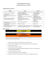
VIII.TROUBLESHOOTING/REPAIR
A.Troubleshooting
Most problems encountered with a PORT-A-COOL® unit are operational problems. When determining which system
that the problem is associated with, first define the problem as several things may cause a particular problem, i.e., “the
pump is not running.” While defining the problem, a careful check of all systems should be made to fully understand the
extent of the problem.
The units consist of three systems — the fan system, the electrical system, and the water system. It is important to
determine which system of the unit the problem is associated with. Certain problems may be associated with more than
one system.
With an understanding of all the systems of the PORT-A-COOL® unit and how they depend on each other, it becomes
much simpler to define and solve any problems.
Although the PORT-A-COOL® unit is designed to be simple to maintain, it will be necessary to have some basic hand
tools (screwdrivers, pliers, adjustable wrenches, etc.) as well a volt/ohm meter for troubleshooting the electrical system.
— WARNING —
USE CAUTION WhEN TROUBLEShOOTING OR REPAIRING ELECTRICAL
COMPONENTS. ENSURE ThAT ALL POWER IS DISCONNECTED FROM ThE UNIT
BEFORE ThE COOLING PADS ARE REMOvED TO GAIN ACCESS TO ThE FAN.
B.RepairandReplacementProcedures
Ensure that all water is removed from the PORT-A-COOL® unit and all power is disconnected. Remove all
impediments to access the component you are checking or replacing.
REPLACING ThE COOLING MEDIA (PADS) (All Models)
CAUTION - DISCONNECT POWER BEFORE PERFORMING ThIS OPERATION
The flap must be removed to allow access to the cooling pads. Start with the center pad, which should
be tilted out from the top and lifted out of the drain trough. The two pads to either side of the center pad
may then be removed in the same manner. To remove the two outside pads, they must first be pulled
sideways toward the center of the PORT-A-COOL® unit until they clear the side retainer before removing in
the same manner as the other pads.
Locate the set screw
in the rear of the unit
on the upper right
side
Remove set screw
and lower front flap
to vertical
position (see
illustration)
48 x 12 x 6
5 pads
Once the front flap
is moved, grasp the
right pad and tilt out
at a 90 degree angle
(see illustration).
Pull the pad up to
remove from unit.
Repeat for other
pads.

PORT-A-COOL OWNER’S MANUAL • PAGE 8
PAGE 27 • PORT-A-COOL OWNER’S MANUAL
PUMP REPLACEMENT
MODELS PAC2K163S, PAC2K163SHD, PAC2K16HPVS
1) DISCONNECT POWER and remove pads.
2) Remove output tubing from insert fitting on base of pump.
(Figure 1-A)
3) Remove the switch box wiring cover and disconnect the 4-pin
quick release connector from the pump switch assembly.
(Figure 1-B)
4) Remove the pump from the sump tank by removing two screws
that hold the pump cover and pump in place.
(Figure 1-C)
5) Remove the pump cover from old pump install onto the
new pump.
6) Reverse the above procedures to install the new pump.
7) Replace the cooling pads, positioning as shown on the air flow label.
8) Reconnect the unit power and test pump.
PUMP REPLACEMENT
MODEL PAC3SVT, PACJS1600, PACJS2400
1) Disconnect electrical power to unit and remove pads.
2) Remove the cover plate on the electrical box to disconnect the
motor quick connect and the zip ties holding it together.
(Figure 1)
3) Remove the pump from the sump.
8) Install new pump by reversing above steps.
Figure 1
Figure 1
1-A
1-B
1-C
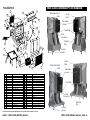
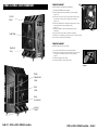
PORT-A-COOL® UNIT OVERVIEW
Control
Panel
Electrical
Plug
Cord Wrap
Hose
Connection
Locking
Casters
Drain
Valve
Water
Adjustment
Valve

PAGE 9 • PORT-A-COOL OWNER’S MANUAL
PORT-A-COOL OWNER’S MANUAL •PAGE 26
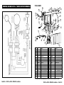
220/50 and 220/60 models may require additional parts. Please contact Customer Service at 936-598-5651 for assistance
30
10
5
36
14
31
4
34
35
9
39
21
28
26
9
27
16
12
29
15
2
24
7
32
8
33
1
37
22
3
19
25
17
20
13
6
31
40
23
23
38
11
18
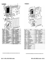
PAC2KCYC01
Port-A-Cool, LLC.
2009
JEB
NEW 02/10/2009
PORT-A-COOL JETSTREAM™ UNIT OVERVIEW
Control
Panel
Adjustable
Louvers
Electrical
Plug
Cord Wrap
Water Adjustment
Valve
Hose
Connection
Locking
Casters
Adjustable
Louvers
Locking
Casters
Electrical
Plug
Hose
Connection
Cord Wrap
Control
Panel
Water Adjustment
Valve
ITEM# PART # DESCRIPTION ITEM# PART # DESCRIPTION
1 BASE-CYCLONE CADDY FRAME 21 PAD6022/26 KUUL PAD SET FOR CYCLONE
2 BLOWER-01 BLOWER HOUSING 22 PAD-SCREEN-CYL CYCLONE UNIT PAD SCREEN
3 BLOWER-WHL-01 BLOWER WHEEL 23 POLY-FTG-06 90 DEG. FITTING FOR SIGHT TUBE
4 BONNET-05 BONNET 24 POWERCORD-02 10ft POWER CORD W / STRAIN RELIEF
5 BOX-UL-02 2 SPD UL ELECTRICAL BOX 25 PRES-REG-01 INLET WATER REGULATOR
6 CAPACITOR-01 PSU 25-30 CAPACITOR 26 PUMP-BRACKET-04 ALUM. BAR PUMP BRACKET
7 CASTER-3-L 3" LOCKING CASTERS 27 PUMP-CYCLONE CYCLONE PUMP - PEM-020
8 CASTER-3-NL 3" CASTERS 28 RIVET-5/32-02 5/32 LARGE RIVET
9 CLAMP-01 1/2" WIRE SPRING CLAMP 29 S-004 FLOAT BOLT
10 CTRL-2SPD-01 2-SPEED SWITCH ASSEMBLY 30 S-006 TEC SCREW S006
11 CTRL-VLV-BRKT VALVE-01 MOUNTING BRACKETS 31 S-009 10/24 x 3/3 TRUSS HEAD SCREW
12 DRAIN-PLUG-01 DRAIN PLUG 32 S-014 5/16 x 1" TRUSS HEAD SCREW
13 FANGUARDCLIP-01 CLIP 33 S-017 5/16 - 18 x 1.5" TRUSS HEAD SCREW
14 FLAP-05 FLAP 34 SPRAY-CYC-01 16" SPRAY BAR
15 FLOAT-02 FLOAT VALVE 35 SPRAY-ACC-04 SPRAY BAR CLIP
16 HOSE-FM18 18" FLOAT HOSE 36 SWITCHPL-2SPD 2 SPEED SWITCH PLATE
17 HOSE-FTG-05 SWIVEL HOSE FITTING 37 TROUGH-04 36"PAC TROUGH
18 LOUVERS-CYC-16 LOUVER FOR CYCLONE 3000 38 VALVE-01 PUMP TO SPRAY BAR CONTROL VALVE
19 MOTOR-013-07 1/3 HP - 2SPD MOTOR 39 TUBE-01 PUMP TO SPRAY BAR TUBING
20 PAC-PLB-01 INLET HOSE ADAPTER 40 TUBE-03 SIGHT TUBE

PORT-A-COOL OWNER’S MANUAL • PAGE 10
PAGE 25 • PORT-A-COOL OWNER’S MANUAL
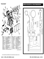
220/50 and 220/60 models may require additional parts. Please contact Customer Service at 936-598-5651 for assistance
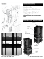
UNIT OPERATION WARNINGS
Control Panel
Water
Adjustment Valve
Electrical Plug
Locking
Casters
Hose Connection
•Notintendedforusebychildren
•Notintendedforusebypersonswithreducedphysical,sensoryor
mentalcapabilities
•Notintendedforusebypersonswithlackofexperienceand
knowledge,unlesstheyhavebeengiveninstructionandare
supervisedduringoperation
•Childrenshouldbesupervisedtoensurethattheydonotplaywiththe
appliance
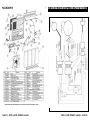
PORT-A-COOL CYCLONE™ 2000 UNIT OVERVIEW
Adjustable
Louvers
ITEM# PART # DESCRIPTION ITEM# PART # DESCRIPTION
1 BLOWER-02 BLOWER HOUSING - CYCLONE2000 17 PAD-SCREEN-2 CYCLONE2000 UNIT PAD SCREEN
2 BLOWER-WHL-2CW CYCLONE2000 BLOWER WHEEL (PART 1) 18 MOTOR-016-01 CYCLONE2000 - 2SPD MOTOR
3 BLOWER-WHL-3CCW CYCLONE2000 BLOWER WHEEL (PART 2) 19 PAC-PLB-14 INLET HOSE ADAPTER for CYCLONE2000
4 BONNET-06 22.5" EXTRUDED BONNET-CYCLONE2000 20 PAD6019/22 KUUL PAD SET FOR CYCLONE2000
5 BOX-UL-02 1 & 2 SPD UL ELECTRICAL BOX 21 POWERCORD-02
10ft POWER CORD W / DOME STRAIN RELIE
F
6 CAPACITOR-04 RUN CAPACITOR FOR CYCLONE2000 22 PUMP-BRACKET-5 PUMP MOUNT BRACKET-CYCLONE2000
7 CASTER-3-L 3" LOCKING CASTERS 23 PUMP-CYC-3 CYCLONE PUMP - OK400
8 CASTER-3-NL 3" CASTERS 24 S-006 TEC SCREW S006
9 CLAMP-01 1/2" WIRE SPRING CLAMP 25 S-009 10/24 x 3/3 TRUSS HEAD SCREW
10 CTRL-2SPD-01 2-SPEED SWITCH ASSEMBLY 26 S-014 5/16 x 1" TRUSS HEAD SCREW
11 CTRL-VLV-BRKT VALVE-01 MOUNTING BRACKETS 27 SPRAY-CYC-02 SPRAY BAR FOR CYCLONE2000
12 DRAIN-PLUG-01 DRAIN PLUG 28 SPRAY-ACC-04 SPRAY BAR CLIP
13 FANGUARDCLIP-01 CLIP 29 SPIN-FTG-02 SPIN FITTING FOR 16" UNIT
14 FLAP-CYC-2 FLAP/SPLASHGAURD-CYCLONE2000 30 SWITCHPL-2SPD 2 SPEED SWITCH PLATE
15 FLOAT-CYC-03 FLOAT VALVE 31 VALVE-01 PUMP TO SPRAY BAR CONTROL VALVE
16 LOUVERS-CYC-11 LOUVER W/MESH - CYCLONE2000 32 TUBE-01 PUMP TO SPRAY BAR TUBING

PAGE 11 • PORT-A-COOL OWNER’S MANUAL
PORT-A-COOL OWNER’S MANUAL • PAGE 24
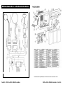
ITEM# PART # DESCRIPTION ITEM# PART # DESCRIPTION
1 BASE-JS/VT CASTER BASE ASSEMBLY FOR JS/VT 20 POWERCORD-02 10FT POWER CORD W/DOME STRAIN RELIEF
2 BLADE-ASSM-08 JS/VT 16" BLADE 21 PAC-PLB-01 INLET HOSE ADAPTER
3 BONNET-03 SPRAY BAR BONNET FOR 16" PAC 22 PAD6024/G 16" PAC REPLACEMENT PAD
4 BOX-UL-03 VAR SPD ELECTRICAL BOX 23 POLY-FTG-06 90DEG FITTING FOR SIGHT TUBE
5 CASTERS-JS-4 4" JS/VT NON-LOCKING CASTER 24 PRES-REG-01 INLET WATER REGULATOR
6 CASTERS-JS-4L 4" JS/VT LOCKING CASTER 25 PUMP-0140-1 PUMP ASSEMBLY FOR 16" UNIT
7 CLAMP-01 1/2" WIRE SPRING CLAMP 26 PUMP-ACC-17 JS/VS PUMP BRACKET
8 CTRL-KNOB-02 KNOB 24"VAR SPD CONTROL 27 S-004 FLOAT BOLT
9 CTRL-VLV-BRKT-1 CONTROL VALVE MOUNTING BRACKET 28 S-006 12-14 BLACK TEC SCREW
10 CTRL-VS-02 VAR SPD SWITCH HARNESS 29 S-009 10-24 X 3/4" TRUSS HEAD SCREW
11 DRAIN-PLUG-01 1/4" NPT PLUG #P-28 FOR 16"UNIT 30 S-014 5/16 X 1" TRUSS HEAD SCREW
12 FLAP-16-01 FRONT FLAP FOR 16" JETSTREAM 31 S-017 5/16 - 18 X 1.5" TRUSS HEAD SCREW
13 FLOAT-02 FLOAT VALVE 32 SPRAY-07 SPRAY BAR FOR 16" PAC
14 HOSE-FM18 18"FLOAT HOSE 33 SPRAY-ACC-04 CLAMP FASTENER FOR SPRAY BAR
15 HOSE-FTG-05 SWIVEL HOSE FITTING 34 SWITCHPL-VARSPD SWITCH COVER PLATE
16 JS-ACC-01 2" THREADED FILLER CAP RING 35 TUBE-01 SOFT PLASTIC TUBE
17 JS-ACC-02 2" THREADED FILLER CAP 36 TUBE-03 SIGHT TUBE
18 LOUVERS-JS FRONT LOUVER FOR JS/VT UNITS 37 VALVE-01 PUMP TO SPRAYBAR CONTROL VALVE
19 MOTOR-013-04 1/6HP VOSTERMAN MOTOR 38 VENT16-INJ-01 VENTURI FOR 16" FAN
220/50 and 220/60 models may require additional parts. Please contact Customer Service at 936-598-5651 for assistance
UNIT OPERATION WARNINGS
Control Panel
Water
Adjustment Valve
Electrical Plug
Locking
Casters
Hose Connection
•Notintendedforusebychildren
•Notintendedforusebypersonswithreducedphysical,sensoryor
mentalcapabilities
•Notintendedforusebypersonswithlackofexperienceand
knowledge,unlesstheyhavebeengiveninstructionandare
supervisedduringoperation
•Childrenshouldbesupervisedtoensurethattheydonotplaywiththe
appliance
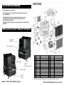
PORT-A-COOL CYCLONE™ 3000 UNIT OVERVIEW
Adjustable
Louvers

PORT-A-COOL OWNER’S MANUAL • PAGE 12
PAGE 23 • PORT-A-COOL OWNER’S MANUAL
7
29
18
6
24
13
11
22
2
4
8
23
36
19
21
33
32
30
1
5
17
26
20
35
9
34
12
14
25
27
28
28
31
10
22
3
15
16
PACJS2400
NEW 01/22/2010
Port-A-Cool, LLC
2010
ITEM# PART # DESCRIPTION ITEM# PART # DESCRIPTION
1 BASE-JS-24 CASTER BASE ASSEMBLY 19 MOTOR-012-06 24” HP MOTOR
2 BLADE-ASSM-24 24” JS FAN BLADE 20 PAC-PLB-01 INLET HOSE ADAPTER
3 BONNET-02 SPRAY BAR BONNET FOR 24” PAC 21 PAD6036/G 24” REPLACEMENT PAD
4 BOX-UL-03 VAR SPD ELECTRICAL BOX 22 POLY-FTG-06 90DEG. FITTING FOR SITE TUBE
5 CASTERS-JS-4 4” JS/VT CASTER 23 POWERCORD-02 POWERCORD W/DOME STRAIN RELIEF
6 CASTERS-JS-4L 4” JS/VT LOCKING CASTER 24 PRESS-REG-01 INLET WATER REGULATOR
7 CTRL-KNOB-02 KNOB FOR 24” VAR/SPD CONTROL 25 PUMP-016-4R PUMP 1/6 HP (LG)
8 CTRL-VS-02 24” VAR/SPD SWITCH HARNESS ASSM 26 PUMP-ACC-18 JS/VT PUMP BRACKET
9 DRAIN-PLUG-01 1/4” NPT PLUG 27 SPRAY-04 SPRAY BAR FOR 24” PAC
10 FLAP-24-01 FLAP FOR 24” PAC 28 SPRAY-ACC-01 #12 NYLON CLIP
11 FLOAT-02 FLOAT VALVE BOX 29 SWITCHPL-VARSPD VAR SPD SWITCH COVE PLATE
12 HOSE-FF-35 1/2” X 35” FEM/FEM HOSE 30 S-006 #12 X 1 1/4” TEK SCREW
13 HOSE-FM18 18” FLOAT HOSE 31 S-009 10-24 X 3/4” TRUSS HEAD SCREW
14 HOSE-FTG-05 FEM/FEM 3/4” X 3/4” BRASS SWIVEL 32 S-014 5/16” - 1” TRUSS HEAD SCREW
15 HOSE-F47 SINGLE FEM HOSE PLUMBING TO PUMP 33 S-017 5/16” - 18 X 1.5” TRUSS HEAD SCREW
16 JS-ACC-01 2” TREADED RING 34 TUBE-03 1/4” POLY SIGHT TUBE
17 JS-ACC-02 2” TREADED CAP 35 VALVE-01 1/2” GATE VALVE
18 LOUVERS-JS-24 LOUVER W/MESH FOR 24” JS/VT 36 VENTURI-24-02 24” VENTURI
220/50 and 220/60 models require additional parts. Please contact Customer Service at 936-598-5651 for assistance
WIRING DIAGRAM for THREE-SPEED MODELS

PAGE 13 • PORT-A-COOL OWNER’S MANUAL
PORT-A-COOL OWNER’S MANUAL • PAGE 22
220/50 and 220/60 models may require additional parts. Please contact Customer Service at 936-598-5651 for assistance
2
3
4
5
6
8
9
11
12
13
14
15
16
17
18
20
21
22
23
24
25
26
27
29
30
10
31
19
1
6
28
28
7
26
PAC163SVT ORG. SN# &SUBSEQUENT
NEW 09/29/2009
Port-A-Cool, LLC
2009
WIRING DIAGRAM for ONE-SPEED MODELS

PORT-A-COOL OWNER’S MANUAL • PAGE 14
PAGE 21 • PORT-A-COOL OWNER’S MANUAL
220/50 and 220/60 models require additional parts. Please contact Customer Service at 936-598-5651 for assistance
WIRING DIAGRAM for VARIABLE SPEED MODELS

PAGE 15 • PORT-A-COOL OWNER’S MANUAL
PORT-A-COOL OWNER’S MANUAL • PAGE 20
220/50 and 220/60 models require additional parts. Please contact Customer Service at 936-598-5651 for assistance
VI. WIRING DIAGRAM for TWO-SPEED MODELS

PORT-A-COOL OWNER’S MANUAL • PAGE 16
PAGE 19 • PORT-A-COOL OWNER’S MANUAL
220/50 and 220/60 models require additional parts. Please contact Customer Service at 936-598-5651 for assistance
220/50 and 220/60 models require additional parts. Please contact Customer Service at 936-598-5651 for assistance

PORT-A-COOL OWNER’S MANUAL • PAGE 18
PAGE 17 • PORT-A-COOL OWNER’S MANUAL
220/50 and 220/60 models require additional parts. Please contact Customer Service at 936-598-5651 for assistance
220/50 and 220/60 models require additional parts. Please contact Customer Service at 936-598-5651 for assistance
Page is loading ...
Page is loading ...
Page is loading ...
Page is loading ...
Page is loading ...
Page is loading ...
Page is loading ...
Page is loading ...
Page is loading ...
Page is loading ...
Page is loading ...
Page is loading ...
Page is loading ...
Page is loading ...
Page is loading ...
Page is loading ...
Page is loading ...
Page is loading ...
Page is loading ...
Page is loading ...
-
 1
1
-
 2
2
-
 3
3
-
 4
4
-
 5
5
-
 6
6
-
 7
7
-
 8
8
-
 9
9
-
 10
10
-
 11
11
-
 12
12
-
 13
13
-
 14
14
-
 15
15
-
 16
16
-
 17
17
-
 18
18
-
 19
19
-
 20
20
-
 21
21
-
 22
22
-
 23
23
-
 24
24
-
 25
25
-
 26
26
-
 27
27
-
 28
28
-
 29
29
-
 30
30
-
 31
31
-
 32
32
-
 33
33
-
 34
34
-
 35
35
-
 36
36
-
 37
37
-
 38
38
-
 39
39
-
 40
40


Ask a question and I''ll find the answer in the document
Finding information in a document is now easier with AI
Related papers
-
PORTACOOL PARKULCYC200 Operating instructions
-
-
-
-
-
-
-
-
Other documents
-
 ProPlumber PPU6 Operating instructions
-
 Port-A-Cool PACCL3600 User guide
-
EURO EDM15XS Owner's manual
-
 Port-A-Cool PAC2KCYC01 Installation guide
-
 Cool-Space CS-M50-VD-60HZ Operating instructions
-
 Port A Cool Cyclone 3000 PAC2KCYC01 Owner's manual
-
 DIAL 71105 Operating instructions
-
 Hessaire MC61V-RFB Installation guide
-
 Cool-Space CS-M36V Operating instructions
-
 Port-A-Cool PACJS1600 User guide


