Page is loading ...

Feeder Strap Winch
Part Number 54812
MF2445EDecember 2015

Contents
Topic Page
MF2445E
2
Chore-Time Warranty . . . . . . . . . . . . . . . . . . . . . . . . . . . . . . . . . . . . . . . . . . . . . . . . . . . . . . . . . . . .3
About This Manual. . . . . . . . . . . . . . . . . . . . . . . . . . . . . . . . . . . . . . . . . . . . . . . . . . . . . . . . . . . . . . .4
Safety Information . . . . . . . . . . . . . . . . . . . . . . . . . . . . . . . . . . . . . . . . . . . . . . . . . . . . . . . . . . . . . . .4
Safety Instructions . . . . . . . . . . . . . . . . . . . . . . . . . . . . . . . . . . . . . . . . . . . . . . . . . . . . . . . . . . . . . . .5
Follow Safety Instructions . . . . . . . . . . . . . . . . . . . . . . . . . . . . . . . . . . . . . . . . . . . . . . . . . . . . . . . . . . . . . . 5
Decal Descriptions . . . . . . . . . . . . . . . . . . . . . . . . . . . . . . . . . . . . . . . . . . . . . . . . . . . . . . . . . . . . . . . . . . . . 5
General. . . . . . . . . . . . . . . . . . . . . . . . . . . . . . . . . . . . . . . . . . . . . . . . . . . . . . . . . . . . . . . . . . . . . . . . .5
Support Information . . . . . . . . . . . . . . . . . . . . . . . . . . . . . . . . . . . . . . . . . . . . . . . . . . . . . . . . . . . . . . . . . . . 5
Planning. . . . . . . . . . . . . . . . . . . . . . . . . . . . . . . . . . . . . . . . . . . . . . . . . . . . . . . . . . . . . . . . . . . . . . . . 6
Installation. . . . . . . . . . . . . . . . . . . . . . . . . . . . . . . . . . . . . . . . . . . . . . . . . . . . . . . . . . . . . . . . . . . . . .6
Remove the Winch Drums . . . . . . . . . . . . . . . . . . . . . . . . . . . . . . . . . . . . . . . . . . . . . . . . . . . . . . . . . . . . . . 6
Attaching the Winch (Wood Trusses) . . . . . . . . . . . . . . . . . . . . . . . . . . . . . . . . . . . . . . . . . . . . . . . . . . . . . 7
(For Angled truss mounting skip to “Angle Truss Mount (54812-2,-4,-6)” on page 10 ) . . . . . . . . . . . . . . 7
Angle Truss Mount (54812-2,-4,-6) . . . . . . . . . . . . . . . . . . . . . . . . . . . . . . . . . . . . . . . . . . . . . . . . . . . . . . .10
Attaching the Winch (Steel Trusses) . . . . . . . . . . . . . . . . . . . . . . . . . . . . . . . . . . . . . . . . . . . . . . . . . . . . . .12
Installing the Winch Motor. . . . . . . . . . . . . . . . . . . . . . . . . . . . . . . . . . . . . . . . . . . . . . . . . . . . . . . . . . . . . .14
Attaching the Straps to the Master Cable . . . . . . . . . . . . . . . . . . . . . . . . . . . . . . . . . . . . . . . . . . . . . . . . . . .15
Screw Hook Installation . . . . . . . . . . . . . . . . . . . . . . . . . . . . . . . . . . . . . . . . . . . . . . . . . . . . . . . . . . . . . . . .16
Winch Operation . . . . . . . . . . . . . . . . . . . . . . . . . . . . . . . . . . . . . . . . . . . . . . . . . . . . . . . . . . . . . . . 17
Operating External Controls. . . . . . . . . . . . . . . . . . . . . . . . . . . . . . . . . . . . . . . . . . . . . . . . . . . . . . . . . . . . .19
Winch Drum Rotation. . . . . . . . . . . . . . . . . . . . . . . . . . . . . . . . . . . . . . . . . . . . . . . . . . . . . . . . . . . . . . . . . .20
Time Clock Setting Instructions. . . . . . . . . . . . . . . . . . . . . . . . . . . . . . . . . . . . . . . . . . . . . . . . . . . . . . . . . .21
Wiring . . . . . . . . . . . . . . . . . . . . . . . . . . . . . . . . . . . . . . . . . . . . . . . . . . . . . . . . . . . . . . . . . . . . . . . . 23
Wiring to 54833 Manual Winch Control.. . . . . . . . . . . . . . . . . . . . . . . . . . . . . . . . . . . . . . . . . . . . . . . . . . .23
Wiring to Chore-Tronics® Control Part No.54832 . . . . . . . . . . . . . . . . . . . . . . . . . . . . . . . . . . . . . . . . . . .24
54832 Chore-Tronics® Winch Timer Internal Wiring. . . . . . . . . . . . . . . . . . . . . . . . . . . . . . . . . . . . . . . . .25
Winch to Timer Control (Part No.54831) Wiring . . . . . . . . . . . . . . . . . . . . . . . . . . . . . . . . . . . . . . . . . . . .26
Winch to Timer Control (Part No.54831) Wiring . . . . . . . . . . . . . . . . . . . . . . . . . . . . . . . . . . . . . . . . . . . .27
54831 Timer Control Internal Wiring. . . . . . . . . . . . . . . . . . . . . . . . . . . . . . . . . . . . . . . . . . . . . . . . . . . . . .28
Parts Listing 54812-X. . . . . . . . . . . . . . . . . . . . . . . . . . . . . . . . . . . . . . . . . . . . . . . . . . . . . . . . . . . . 30
Part Numbers . . . . . . . . . . . . . . . . . . . . . . . . . . . . . . . . . . . . . . . . . . . . . . . . . . . . . . . . . . . . . . . . . . 31
Feeder Winch Drum Part No. 54842 . . . . . . . . . . . . . . . . . . . . . . . . . . . . . . . . . . . . . . . . . . . . . . . . . . . . . .32
Horizontal Mount Kit P/N 51533-1 . . . . . . . . . . . . . . . . . . . . . . . . . . . . . . . . . . . . . . . . . . . . . . . . . . . . . . .33
Angled Truss Mount Hardware Kit P/N 51533-2. . . . . . . . . . . . . . . . . . . . . . . . . . . . . . . . . . . . . . . . . . . .34
Manual Winch Control Part No.54833 . . . . . . . . . . . . . . . . . . . . . . . . . . . . . . . . . . . . . . . . . . . . . . . . . . . .35
CHORE-TRONIC Winch Control Part No. 54832 . . . . . . . . . . . . . . . . . . . . . . . . . . . . . . . . . . . . . . . . . . .36
Timed Winch Control Part No. 54831 . . . . . . . . . . . . . . . . . . . . . . . . . . . . . . . . . . . . . . . . . . . . . . . . . . . .37

Feeder Strap Winch Chore-Time Warranty
MF2445E
3
Chore-Time Group, a division of CTB, Inc. (“Chore-Time”) warrants the new CHORE-TIME Turbo Fans
®
manufactured
by Chore-Time to be free from defects in material or workmanship under normal usage and conditions, for One (1) year
from the date of installation by the original purchaser (“Warranty”). Chore-Time provides for an extension of the
aforementioned Warranty period (“Extended Warranty Period”) with respect to certain Product parts (“Component Part”) as
set forth in the table below. If such a defect is determined by Chore-Time to exist within the applicable period, Chore-Time
will, at its option, (a) repair the Product or Component Part free of charge, F.O.B. the factory of manufacture or (b) replace
the Product or Component Part free of charge, F.O.B. the factory of manufacture. This Warranty is not transferable, and
applies only to the original purchaser of the Product.
CONDITIONS AND LIMITATIONS
THIS WARRANTY CONSTITUTES CHORE-TIME’S ENTIRE AND SOLE WARRANTY AND CHORE-TIME
EXPRESSLY DISCLAIMS ANY AND ALL OTHER WARRANTIES, INCLUDING, BUT NOT LIMITED TO,
EXPRESS AND IMPLIED WARRANTIES, INCLUDING, WIHTOUT LIMITATION, WARRANTIES AS TO
MERCHANTABILITY OR FITNESS FOR PARTICULAR PURPOSES. CHORE-TIME shall not be liable for any direct,
indirect, incidental, consequential or special damages which any purchaser may suffer or claim to suffer as a result of any
defect in the Product. Consequential or Special Damages as used herein include, but are not limited to, lost or damaged
products or goods, costs of transportation, lost sales, lost orders, lost income, increased overhead, labor and incidental costs,
and operational inefficiencies. Some jurisdictions prohibit limitations on implied warranties and/or the exclusion or
limitation of such damages, so these limitations and exclusions may not apply to you. This warranty gives the original
purchaser specific legal rights. You may also have other rights based upon your specific jurisdiction.
Compliance with federal, state and local rules which apply to the location, installation and use of the Product are the
responsibility of the original purchaser, and CHORE-TIME shall not be liable for any damages which may result from non-
compliance with such rules.
The following circumstances shall render this Warranty void:
• Modifications made to the Product not specifically delineated in the Product manual.
• Product not installed and/or operated in accordance with the instructions published by the CHORE-TIME.
• All components of the Product are not original equipment supplied by CHORE-TIME.
• Product was not purchased from and/or installed by a CHORE-TIME authorized distributor or certified representative.
• Product experienced malfunction or failure resulting from misuse, abuse, mismanagement, negligence, alteration, acci-
dent, or lack of proper maintenance, or from lightning strikes, electrical power surges or interruption of electricity.
• Product experienced corrosion, material deterioration and/or equipment malfunction caused by or consistent with the
application of chemicals, minerals, sediments or other foreign elements.
• Product was used for any purpose other than for the care of poultry and livestock.
The Warranty and Extended Warranty may only be modified in writing by an officer of CHORE-TIME. CHORE-TIME
shall have no obligation or responsibility for any representations or warranties made by or on behalf of any distributor,
dealer, agent or certified representative.
Effective: April, 2014
Chore-Time Group, A division of CTB, Inc.
PO Box 2000
Milford, Indiana 46542-2000 USA
Phone (574) 658-4101 Fax (877) 730-8825
Internet: www.choretimepoultry.com
E-mail: [email protected]m
Chore-Time Warranty
Component Part Extended Warranty Period
RXL Fan (except motors and bearings)
Three (3) Years
TURBO® Fan (except motors and bearings) Three (3) Years
TURBO® Fan fiberglass housing, polyethylene cone, and cast aluminum blade. Lifetime of Product
TURBO® fan motor and bearings. Two (2) Years
Chore-Time® Poultry Feeder Pan Three (3) Years
Chore-Time® Rotating Centerless Augers (except where used in applications involving high
moisture feed stuffs exceeding 17%)
Ten (10) Years
Chore-Time Steel Auger Tubes Ten (10) Years
ULTRAFLO® Breeder Feeding System auger and feed trough. Five (5) Years
ULTRAPAN® Feeding System augers . Five (5) Years

About This Manual Feeder Strap Winch
4
MF2445E
The intent of this manual is to help you in two ways. One is to follow step-by-step in the order of assembly of your
product. The other way is for easy reference if you have questions in a particular area.
Important: Read ALL instructions carefully before starting construction.
Important: Pay particular attention to all SAFETY information.
• Metric measurements are shown in millimeters and in brackets, unless otherwise specified. “ " ” equals inches
and “ ' ” equals feet in English measurements.
Examples:
1" [25.4]
4' [1 219]
• Optional equipment contains necessary instructions for assembly or operation.
• Very small numbers near an illustration (i.e.,
1257-48) are identification of the graphic, not a part number.
Note: The original, authoritative version of this manual is the English version produced by CTB, Inc. or any of
its subsidiaries or divisions, (hereafter collectively referred to as "CTB"). Subsequent changes to any manual
made by any third party have not been reviewed nor authenticated by CTB. Such changes may include, but are
not limited to, translation into languages other than English, and additions to or deletions from the original
content. CTB disclaims responsibility for any and all damages, injuries, warranty claims and/or any other
claims associated with such changes, inasmuch as such changes result in content that is different from the
authoritative CTB-published English version of the manual. For current product installation and operation
information, please contact the customer service and/or technical service departments of the appropriate CTB
subsidiary or division. Should you observe any questionable content in any manual, please notify CTB
immediately in writing to: CTB Legal Department, P.O. Box 2000, Milford, IN 46542-2000 USA.
Caution, Warning and Danger Decals have been placed on the equipment to warn of potentially dangerous
situations. Care should be taken to keep this information intact and easy to read at all times. Replace missing or
damaged safety decals immediately.
Using the equipment for purposes other than specified in this manual may cause personal injury and/or damage to
the equipment.
Safety–Alert Symbol
This is a safety–alert symbol. When you see this symbol on your equipment, be alert to the
potential for personal injury. This equipment is designed to be installed and operated as safely
as possible...however, hazards do exist.
Understanding Signal Words
Signal words are used in conjunction with the safety–alert symbol to identify the severity of the warning.
DANGER indicates an imminently hazardous situation which, if not avoided, WILL result in death or
serious injury.
WARNING indicates a potentially hazardous situation which, if not avoided, COULD result in death or
serious injury.
CAUTION indicates a hazardous situation which, if not avoided, MAY result in minor or moderate
injury.
About This Manual
Safety Information

Feeder Strap Winch Safety Instructions
MF2445E
5
Follow Safety Instructions
Carefully read all safety messages in this manual and on your equipment safety signs. Follow recommended
precautions and safe operating practices.
Keep safety signs in good condition. Replace missing or damaged safety signs.
Decal Descriptions
WARNING: CRUSH HAZARD
This decal is placed on the side of the winch.
Do not stand under the feeder line while operating the electric winch. This is
a potentially hazardous situation which, if not avoided, may result in death or
serious injury.
DANGER: Electrical Hazard
Disconnect electrical power before inspecting or servicing equipment
unless maintenance instructions specifically state otherwise.
Ground all electrical equipment for safety.
All electrical wiring must be done by a qualified electrician in accordance
with local and national electric codes.
Ground all non-current carrying metal parts to guard against electrical
shock.
With the exception of motor overload protection, electrical disconnects and
over current protection are not supplied with the equipment.
CAUTION:
Use caution when working with the Auger springing Auger may cause personal
injury.
Support Information
The Chore-Time Feeder Strap Lift Winch has been designed to raise and lower poultry feeders. Using this
equipment for any other purpose or in a way not within the operating recommendations specified in this manual
will void the warranty and may cause personal injury.
This manual is designed to provide comprehensive planning and installation information. The Table of Contents
provides a convenient overview of the information in this manual.
Please refer to the feeding system manual for additional information about the feeding system suspension.
Safety Instructions
General
Manboot 3/98

Planning Feeder Strap Winch
6
MF2445E
Please read the installation instructions in this manual prior to beginning the installation. This manual provides
the necessary information on the installation, operation, and maintenance of the Strap Lift Winch System. See
your feeding system manual for additional information about the feeding system suspension.
The Strap Lift Winch System is made up of a series of worm gear drives powered by a 1 HP. motor. The strap lift
winch system has a lift speed of 1.5 - 3 ft. per minute. Total strap lift straight pull is 12 ft.
Important! The Strap Lift Winch System has a working load of 3,000 pounds to handle feed lines up to 600’
[183m]. The Winch is designed to be installed in the center of the house and lift and lower from both directions
to center.
The strap lift winch utilizes a 1 HP. 230 VAC 60 HZ. single phase motor with a 600:1 reduction ratio.
1.Mount the Winch and Support Board to the trusses using the main winch cable as a guide for alignment.
2.Attach the Strap Winch Support Board (with the Strap Winch secured) to the ceiling at the center of the
feeder line, The Support Board must be parallel to the feeder line and must span at least 3 trusses in a wood
frame house, or 2 trusses in a steel framed house. If the hopper is located at the center of the feeder line,
locate the Strap Winch a few feet offset from the center of the feeder line. However, the winch drum must
be directly in line with where the main cable is installed.
3.Use (3) three lag screws for each truss end and two lag screws in the center of the board next to the winch.
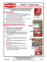
Remove the Winch Drums
4.Unpack the Strap Winch.
5.To ease installation,
remove the Winch
Drums by removing the
Cap Screws as shown.
Planning
Installation
Figure 1. Suspension for systems up to 600’ [183 m]
(54841) Socket Head Screw
Figure 2. Remove the Winch Drums
(54842)
Winch Drum

Feeder Strap Winch Installation
MF2445E
7
Attaching the Winch (Wood Trusses)
Horizontal Flat Position Installation (54812-1, 54812-3, or 54812-5)
(For Angled truss mounting skip to “Angle Truss Mount (54812-2,-4,-6)” on page 10 )
Drilling Holes in Mounting Board
1.Cut a 2 x 12 Board long enough to span three trusses when mounting to wood Trusses (See Figure 3.).
2. Pre-drill 1/2" [13mm] holes in the Mounting Board as shown using the Center of the Mounting Board as a
guide.
7-1/4"[18.42cm]
6-5/16"
12-5/8" [32.07 cm]
2 x 12 [3.81cm x 28.58cm]
Lumber
[16.03 cm]
6-5/16"
[16.03 cm]
3-3/4"
2 x 12 [3.81cm x 28.58cm]
Mounting Board must
be long enough to Span
three trusses for wood truss or
Figure 3. Drilling Holes for Mounting
Center of Mounting Board
Center of Middle Truss
[95.3mm]
Center of Mounting Board
Center of Mounting Board
3-5/8"[9.21cm]
Minimum
two trusses fr steel truss construction.
Truss
Truss
Truss

Installation Feeder Strap Winch
8
MF2445E
Attaching the Winch to the Mounting Board
1.Attach the Winch to the Mounting Board as shown below.
Attaching the Straps and Re-Attaching the Drums
1.Remove the Nuts (54840) and one Disk (54837) from each Drum and attach Straps as shown.
2.Re-install the Disks and attach the Drums to the Winch with Cap Screws (54841).
6x (4415-7)
1/2"-13 x 2-1/2" Bolt
6x (54858)
1/2" Flat Washer
6x (8917)
1/2"-13 x Lock Nut
6x (8917)
1/2"-13 x Lock Nut
6x (4415-7)
1/2"-13 x 2-1/2" Bolt
Figure 4. Attaching Winch to Mounting Board
Hardware: Full Scale
6x (54858)
1/2" Flat Washer
(54841)
Slip Belt over Bolt
(54840) Nut
Figure 5. Attaching Winch to Mounting Board
Socket Head Screw
(54837) Disk

Feeder Strap Winch Installation
MF2445E
9
Attaching the Mounting Board to the Trusses
1.With the Mounting Board still on the floor Mark a Chalk-line parallel with the Mounting Board lined up with
the center of the Straps (See Figure 6.).
2.Line up the Chalk-line with the Feeder Line and attach the Mounting Board to the Trusses
(Hardware not Included).
IT IS VERY IMPORTANT TO MAKE SURE THE MASTER CABLE IS CENTERED WITH
THE WINCH DRUMS. If the alignment is not correct the straps WILL NOT track onto the
winch drums correctly.
Important!
11/16" [17.46mm]
chalk-line to
with Center of Feed Line
Center of Feed Line
Mounting Hole
Chalk-line
Chalk-line
Line up Chalk-line
Figure 6. Attaching the Mounting Board to the Trusses
Three 4" [10.2cm]
Three 4" [10.2cm]
Three 4" [10.2cm]
Line up the Center of
the Mounting
Board with the Center
of the Middle Truss.
Lag Screws
Lag Screws
Lag Screws
Master Cable
Parallel
Parallel

Installation Feeder Strap Winch
10
MF2445E
Angle Truss Mount (54812-2,-4,-6)
Attaching the Angle Mount Bracket to the Winch
When mounting the Winch to angled trusses it is
necessary to use an Angle Mount Bracket.
1.Attach the Angled Truss Mount (54915) as shown
(See Figure 7.) Finger tighten hardware for now.
You will use the Bracket as a drill template in the
next step and then it will be un-assembled.
2.Cut a 2 x 12 [3.81cm x 28.58cm] to a length that will
span three trusses when mounting to wood trusses
(See Figure 8.)
3.Fasten the Winch to the Mounting Board 3-3/4"
[95.3mm] offset from the center of the board to
avoid interference when mounting to the trusses, and
flush with the edge. Slots in the Mounting Bracket
allow for adjustment. Tighten down the (8917)
Locknuts.
6x (8917)
(54916)
Lower Base Mount
(54915)
Angled Truss Mount
3x (54858)
1/2" Washer
1/2-13 Locknut
Figure 7. Angle Truss Mount
2 x 12 [3.81cm x 28.58cm]
Mounting Board must be long enough
to Span three trusses (Wood Truss) or
two trusses (Steel Truss).
Flush with
3-3/4"
[95.3mm]
(Both Sides)
Center of
6x (40268)
3/8 x 1-1/2"
Minimum
Mounting Board
Lag Screw
Center of
Mounting Board
Mounting Board
3-3/4"
[95.3mm]
Minimum
Figure 8. Attaching the Mounting Board to the Trusses
(8917)
Use for Adjustment.
Tighten once attached.

Feeder Strap Winch Installation
MF2445E
11
Attaching the Straps and Re-Attaching the Drums
1.Remove the Nuts (54840) and one Disk (54837) from each Drum and attach Straps as shown.
2.Re-install the Disks and attach the Drums to the Winch with Cap Screws (54841).
Attaching the Mounting Board to the Trusses
1.With the Mounting Board still on the floor Mark a Chalk-line parallel to the Mounting Board lined up with
the center of the Straps (See Figure 10.).
2.Line up the Chalk-line with the Feeder Line below and attach the Mounting Board to the Trusses
(Hardware not Included).
IT IS VERY IMPORTANT TO MAKE SURE THE MASTER CABLE IS CENTERED
WITH THE WINCH DRUMS. If the alignment is not correct the straps WILL NOT track
onto the winch drums correctly.
(54841)
Slip Belt over Bolt
(54840) Nut
Figure 9. Attaching Straps and Re-attaching Drums
Socket Head Screw
(54837) Disk
Important!
Chalk-line
Parallel
Parallel
Chalk-line
Lag Screws
Lag Screws
Chalk-line lined up
with and parallel to
Center of Truss
Center of Mounting Board lined up
Figure 10. Attaching Mounting Board to the Trusses
Truss
Truss
Truss
with Center of Truss if spanning
three trusses (Wood Truss).
Feed Line Maser Cable

Installation Feeder Strap Winch
12
MF2445E
Attaching the Winch (Steel Trusses)
Make a Steel Mounting Plate
1.If mounting to Steel Trusses we recommend a 3/8'' [9.5 mm] thick steel plate welded to two pieces of angle
iron that are each long enough to span at least 2 Trusses.
Important! Consult a Structural Engineer for specifying adequate structural support. CTB, Inc. is not
responsible for Structural integrity of the building or the angle iron used when mounting.
2.Pre-drill 1/2" [12.7 mm] holes in the Steel Plate as shown.
Attach Winch to Fabricated Plate
1.Attach the Winch to the Plate. Hardware
is not supplied for mounting.
6-5/16"
12-5/8" [32.07 cm]
[16.03 cm]
6-5/16"
[16.03 cm]
Angle Iron
Truss
Steel Plate 3/8" [9.5mm]
thick minimum
Truss
Figure 11. Attaching Mounting Board to the Trusses
Steel Plate
Drill 1/2" [12.7mm]
holes in Plate
7-1/4" [18.42cm]
Center of Plate
3-5/8"
[9.21cm]
Figure 12.Attach Winch to Plate

Feeder Strap Winch Installation
MF2445E
13
Attaching the Straps and Re-Attaching the Drums
1.Remove the Nuts (54840) and one Disk (54837) from each Drum and attach Straps as shown.
2.Re-install the Disks and attach the Drums to the Winch with Cap Screws (54841).
Attach the Winch and Angle Iron to Trusses
1.Line up the Center of the Straps with the Feeder Line below and attach the Angle Iron to
the Trusses (Hardware not Included).
IT IS VERY IMPORTANT TO MAKE SURE THE MASTER CABLE IS CENTERED WITH
THE WINCH DRUMS. If the alignment is not correct the straps WILL NOT track onto the winch
drums correctly.
(54841)
Slip Belt over Bolt
(54840) Nut
Figure 13. Attaching Straps and Re-attaching Drums
Socket Head Screw
(54837) Disk
Important!
Lined up with and Parallel
to the Feed Line Master Cable
Figure 14.Attaching the Winch to the Trusses

Installation Feeder Strap Winch
14
MF2445E
Installing the Winch Motor
1.Apply Anti-Seize to the entire surface of the Motor Shaft
2.Insert the Key (Supplied with Motor) and attach the Motor with four Bolts and Nuts. (Supplied with Motor).
Square Key4x Washer
(Included with Motor)
4x Bolt
(Included with Motor)
(Included with Motor)
Figure 15.Attaching the Motor

Feeder Strap Winch Installation
MF2445E
15
Attaching the Straps to the Master Cable
Cable must be centered with the strap.
1.With the cable pulled taught and secured to the truss on each side of the winch cut the cable. Strap must be
fully extended before installing the Cable on the "D" ring.
2.Install a Thimble to the Winch Strap "D"
Ring.
3.Route the Master Cable through the "D"
Ring over the Thimbles.
4.Install two Cable Clamps.
Figure 16.Attaching the Motor
Thimble
Winch Strap
Master Cable
Cable Clamp
Figure 17.Attaching Cable to Straps


Feeder Strap Winch Winch Operation
MF2445E
17
Initial Setup (Before Birds)
Setting Down Limit
During initial setup set the down limit to approximately 20". This will be close to the height for Male Birds. This
can be fine tuned later when the Birds are in the house.
1.Put the local/remote Switch in the "Local" position.
2.Use the up/down switch up to adjust the Feeders to approximately 20" [51 cm] off the floor (See Figure 19)..
3.Pull the Spring Clip from the Down Limit Nut. Rotate the Brass Nut until the Down Limit Switch light
comes on and the Switch Clicks (See Figure 20).
DO NOT OVER PULL SPRING CLIP!
4.NOTE: If the Down Over Travel Light is activated, the system will stop operation! If this happens you will
need to rotate the Brass Nut back from the switch arms.
5.Lock the Spring Clip back into a groove in the Brass Nut once desired height is reached.
Winch Operation
20" [51 cm]
Up/Down Switch
Switch in "Local" position
Figure 19.Down Limit Switch
Important!
Figure 20.Down Limit Diagram
"Down" Over Travel Light
Down Limit
Down Limit
Brass Nut
Spring Clip
"Down" Limit Switch Light

Winch Operation Feeder Strap Winch
18
MF2445E
Initial Setup
Setting Up Limit
Before birds the Up limit should be set high enough to be able to get vehicles into the house to bring in litter.
1.Put the local/remote Switch in the "Local" position
2.Use the up/down switch up to lift the Feeders up to a level that will allow litter trucks to enter the building.
3.Pull the Spring Clip from the Up Limit Nut. Rotate the Brass Nut until the Up Limit Switch Light comes on,
and the Up Limit Switch is energized. (Should hear a click) (See Figure 22).
DO NOT OVER PULL SPRING CLIP!
4.NOTE: If the "Up" Over Travel Light is activated, the system will stop operation! If this happens you will
need to rotate the Brass Nut back from the switch arms.
5.Lock the Spring Clip back into a groove in the Brass Nut once the desired height is reached.
Up/Down Switch
Switch in "Local" position
Figure 21.Up Limit Setup
Important!
Up Limit
Figure 22.Up Limit Diagram
Up Limit
Brass Nut
Spring Clip
"Up" Over Travel Light
"Up" Limit Switch Light

Feeder Strap Winch Winch Operation
MF2445E
19
Setting Limit Switches with Birds in House
1.After shavings have been delivered, reset the "down" limit to
accommodate the size of the birds. Adjust the brass nut as
you did in “Setting Down Limit” on page 17.
2.Adjust the Up limit for the height of the Feed Scale.
Adjust the Brass Nut as you did in “Setting Up
Limit” on page 18.
Always replace covers on Winch Controls after adjusting or servicing. Failure to replace covers
could result in moisture or dust entering, causing damage to the Circuit Boards and/or their
Components.
Operating External Controls
To operate the Winch using an external Control...
1.Place the up/down switch to the center position
2.Place the local/remote switch to remote position
Manual Control (Part No. 54831)
1.Push the up/down switch. This will operate the winch in
the up or down direction. You must push and hold the
switch in the desired direction. Limit switches will
operate as set.
Timed Control (Part No. 54831)
1.Push and hold the up/down switch on the control box. Limit switches will operate as set.
2.After programming the digital time clock (see digital clock section for instruction), set the time that
you wish the feeder to be lowered. The time clock will not lift the feed line. Lifting the feed line
must be done manually.
Chore-Tronics Control (Part No. 54832)
1.After selecting the relay you wish to lower the feed line, program a time for the feeder to be
lowered. Lifting the Feeder must be done manually.
2.The up/down switch on the Control will raise or lower the feed line. The limit switches will operate
as set.
Figure 23.Down Limit with Birds in House
Feed Scale
Figure 24.Up Limit with Birds in House
Caution!
Figure 25.External Controls

Winch Operation Feeder Strap Winch
20
MF2445E
Full Manual Operation
This winch incorporates a 5/8" [16 mm] hex
extension on the main input shaft (opposite
motor) for full manual operation.
In the event of a power or control failure, the
strap winch can be operated manually.
A power failure would require use of a strong
battery drill. This will be a slow process since
the winch is configured with a 600:1 gear
reduction ratio. The manual feature is mostly
intended for lowering the feeder to
accommodate feeding the male birds.
Lowering the feeder with the strap winch
requires much less torque input than trying to
raise the feeder.
If the manual mode of operation is required due to a motor or control failure, where manual toggle
switches are not functioning, then a ½" electric drill is the most practical tool to use in the full manual
mode.
WARNING! : If attempting full manual operation of winch, disconnect power to the winch at the circuit
breaker to prevent unexpected starting (power restoration) while trying to operate manually.
CAUTION: If operating in full manual mode, be careful not to exceed the normal travel distances up and
down which the limit switches are set for. If this happens, then limit and/or safety switches could be
damaged by the brass actuator nuts in the integral winch control head. If safety switch/es are contacted
by the limit nuts, the nut/s would need to be adjusted away from the switches to allow the winch to
function normally with electric power restored.
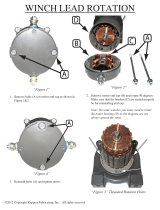
Winch Drum Rotation
Check for proper Rotation. When operating in the up direction the Drum should pull the belts as shown
below.
5/8" [16mm]
Hex Extension
Figure 26.Full Manual Operation
Figure 27.Winch Drum Rotation
/