Page is loading ...

Caravanman 85 Professional
Benutzerhandbuch
Deutsch
Brillantes FernsehenBrillantes Fernsehen

Stand: V1.1 Juli 2012
Caravanman 85 Professional
user manual
English
Brillantes Fernsehen
Brillantes Fernsehen

ENGLISH ENGLISH
Table of contents
02
03
Megasat Werke GmbH | Industriestraße 4a | D-97618 Niederlauer | www.megasat.tv | info@megasat.tv
1. Introduction
Specication 6
Antenna System Overview 7
Direct Broadcast Satellite Overview 8
System Components 9
2. Installation
Unpacking the Unit 10
Preparing for the installation 11
Selecting the location 12
Equipment and cable installation 13
Setting the LNB Skew Angle 14
3. Operation
Receiving Satellite TV Signals 15
Turning the System On/O 16
Changing Channels 16
Watching TV 16
Switching between Satellites 17
Operating the IDU 18
4. Troubleshooting
Simple Check 23
Causes and Remedies 24
Firmwareupgrade 26
5. Gluing instructions 28
Figures
Figure 1-1 System Diagram 7
Figure 1-2 Satellite Blockage 8
Figure 1-3 System Components 9
Figure 2-1 Unpacking the Unit 10
Figure 2-2 Selecting the Location 12
Figure 2-3 Satellite Signals 14
Figure 2-4 Best Skew Angle 14
Figure 3-1 IDU LCD Screen 17
Figure 3-2 Appearance of IDU 18
Figure 3-3 Functions of LCD Display 18
Figure A-1 Coverage Map 25
Figure C-1 SD Memory Card 26
Figure C-2 Formatting SD Memory Card 26
Figure C-3 Writing Software 27
Figure C-4 Finishing to Write 27
Tables
Tabelle 1-1 Specication 6
Tabelle 2-1 Delivery 10
1 Appendix A Satellite Coverage Map 25
2 Appendix B Firmware Upgrade 26

ENGLISH ENGLISH
04
05
Notes, Cautions, and Warnnings Introduction
!
Caution – Improper handling by unqualied personnel can cause se-
rious damage to this equipment. Unqualied personnel who tamper
with this equipment may be held liable for any resultant damage to the
equipment.
Install under DRY condition ONLY! Do not install this system in the rain,
or under any wet conditions. Moisture may aect electronics and void
warrenty!
Warning – Need 2 people to install the antenna onto the roof. Do not try
to install the antenna by yourself.
Note – Before you begin, carefully read each of the procedures in this
manual. If you have not performed similar operations on comparable
equipment, do not attempt to perform these procedures.
The satellite antenna system is the innovative and a technologically ad-
vanced satellite Positioner system. The antenna has a unique combinati-
on of state-of-the art components with the most sophisticated satellite
acquisition and tracking programs to provide the following features:
• Fast satellite acquisition
• Compatible with any Satellite Receiver
• Compatible with all Direct Broadcast Satellites (DBS)
• Built-in Digital Broadcast Receiver(DVB)
• Capable of High Denition receiving
Specication 7
Antenna System Overview 8
Direct Broadcast Satellite Overview 9
System Components 10

ENGLISH ENGLISH
06
07
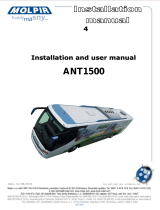
Connection exampleSpecication
Antenna Type O-set Dish
LNB Typ Twin LNB
Frequency Band Ku Band
Antenna Dish Dimension 880x820mm
Antenna Weight 15kg
Antenna Gain 39dBi
Minimum EIRP 47dBW
Polarization V/H or RHCP/LHCP
Type of Stabilization 2-Axis Geared Motor
Elevation Range 0° to 70°
Azimuth Range 360°
Tracking Rate 50°/sec
Temperate Range -20° to 70°
Power 12 VDC
Tabelle 1-1 Technische Daten
IDU
Control cable
positive pole
Coax cable
Minus pol
Plus ignition
(+)(-)
Plus ignition
Power supply
Coax cable
The Caravanman 85 Professional automatically
moves into the folded state as soon as the igni-
tion key is turned. The display of the controller is
„IGNITION“ is displayed.
12V DC via battery (positive-permanent
systems) or optional DC power supply
230V/12V. Ensure that a current is assu-
red of at least 5 amps.
You can select
any port on
the controller.
Set-top-box 1
Television 1
Set-top-box 2
Television 2
(+) (-)
Note
The control cable (10m)
can not be reduced, because
that can cause interference.

ENGLISH ENGLISH
08
09
System Components
Direct Broadcast Satellite Overview
Gutes Empfangssignal Schlechtes Empfangssignal
Direct Broadcast Service (DBS) satellites broadcast audio, video and data information
from satellites located 22,000 miles in space. A receiving station, such as the antenna,
should include a dish and satellite receiver to receive the signals and process them for
use by the consumer audio and video equipment. The system requires a clear view of
the satellite to maximize the signal reception.
The antenna unit houses the antenna positi-
oning mechanism, LNB (low noise block), and
control elements within a random. Weather
tight connectors join the power, signal, and
control cabling from the below deck units.
The IDU is the system’s user interface, provi-
ding access to the system and its functions
through an LCD and three buttons. The IDU
also serves as the vessel’s junction box, al-
lowing the system to use vessel power, and
supply and receive data to/from the antenna
unit.
Antenna Unit
IDU (In Door Unit)
Figure 1-2 Satellite Blockage Figure 1-3 System Components
Objects such as tall lighthouse, bridges and big ship that block this view will cause a loss
of signal. The signal will be quickly restored once the antenna has a clear line of sight
again. Heavy rain, cloud, snow or ice may also interfere with the signal reception quality.
If the satellite signal is lost due to blockage or severe weather condition, services from
the receiver will be lost (picture will freeze frame and may disappear). When the satellite
signal strength is again high enough, then the receiver will resume providing desired
programming services.

ENGLISH ENGLISH
10
11
Installation Preparing for the installation
This section provides a general explanation on how to install the antenna properly.
The steps in the installation and setup process are as follows:
Unpacking the unit 10
Preparing for the installation 11
Selecting the location 12
Equipment and cable installation 13
Setting the LNB Skew Angle 14
Warning : Things to consider when installing the antenna
• Turn off the power when attaching or detaching the antenna.
• Make sure that the attached satellite is fixed on the flat surface.
• When attaching, ensure that all the products are adhered properly.
• nsure that all the cables are connected properly.
1. Verication of the Vessel’s Power Supply.
• Confirm that the vessel’s power supply is 12V DC 5A.
NOTE: Look for a sufficiently charged battery when you align the antenna. Loading
procedures can result in abnormal alignment. Be guaranteed for operation over the
230V/12V board voltage or power supply unit must be an output of 12V/5A.
2. Verication of the set-top-box and IDU’s attachment and the electricity supply
• Attach Satellite Receiver and IDU in the interior of the vessel or the trunk.
• Connect the power of Satellite Receiver and IDU.
• Once the power of Satellite Receiver and IDU is verified, it confirms that both Satellite
Receiver and IDU are working normally.
3. Handling of the fastening and installation.
• Attach the satellite on the flat surface area of the vessel’s roof.
• Connect each end of the Coaxial antenna cable to the satellite’s terminal and the IDU.
• Connect the IDU and the Satellite Receiver box together through the coaxial cable.
• Make sure that the satellite is working normally, once the power is supplied.
Table 2-1 Parts included
• Antenna Unit
• 85cm Dish
• IDU(In Door Unit)
• Main Cable ( Attached Antenna Pedestal ) (10m)
• Coaxial Cable (10m)
• Coaxial Cable (1m)
• Power Cable (1m)
• Gluing set (optional)
Unpacking the unit
1. Open box and remove packing material.
The following items are included in the packaging of the antenna.
2. Lift dome out of box vertically. Then lift unit out of box vertically. Do not turn box and
“roll” out, or turn upside down to remove.
Install Tools and Materials
The antenna system is designed for simple installation and setup. However, the following
list of equipment or items should be available during installation of the antenna:
• Electric drill and drill bits
• Socket wrench
• Silicon sealant
• Fastener suitable for specific application
Lift Unit straight up out of the
carton!
Figure 2-1 Unpacking the unit
!

ENGLISH ENGLISH
12
13
Determine the optimum mounting location for the antenna random assembly. It should
be installed where:
1. The antenna has a clear line-of-sight view to as much of the sky as is practical. Choose
a location where masts or other structures do not block the satellite signal from the dish
as the vessel turns.
2. The antenna is at least 5 feet away from other transmitting antennas (HF, VHF and
radar) that may generate signals that may interfere with the antenna. The further away
the antenna is from these other antennas, the less impact their operation will have on it.
If these conditions cannot be entirely satisfied, the site selection will inevitably be a “best”
compromise between the various considerations.
This offers a general explanation of how to install the IDU and satellite receiver properly
to the inside of vessel connecting with Main Cable and coaxial cable.
1. The Coaxial cable and Main cable is routed from the antenna to the IDU inside the
vessel.
2. After Once deciding where to place the IDU and satellite receiver, make sure that
both units are placed in a dry and protected area.
3. The IDU and satellite receiver should be placed away from any heat source and in an
area with proper ventilation.
4. Ensure that there are at least 3cm of space around both units for ventilation and
connection of cables. Do not stack the units on top of each other.
5. The following describes the basic wiring configurations for the antenna system.
• Connect the Main Cable and Coaxial cable to the antenna port on the back of the
IDU.
• Connect one end of the supplied coaxial cable to the receiver port on the back of
the IDU.
• Connect the other end of the coaxial cable to the satellite receiver.
Poor Location
Best Location
Figure 2-2 Selecting the location
Perform a through site inspection on the roof for the antenna to be
mounted.
1. The antenna must have a clear view of the sky and the horizon at all the
directions to avoid blockage of the satellite signal.
2. The antenna should be on the top of the vehicle.
Selecting the location Equipment and cable installation
• 4-pin power cable
- RED Continuous positive battery (not without a vehicle security)
- BLACK Mass
- YELLOW ignition plus vehicle (without fuse)
- BLACK Mass
• 12-pin control cable (10m) shall not be reduced
• 10m antenna cable can be adjusted in length
• 1m aerial cable can be adjusted in length
Note:

ENGLISH ENGLISH
14
15
OperationSetting the LNB skew angle
Signals transmitted in vertical(red) and horizontal(blue) wave offset exactly 90º from
each other. Since linear satellite signals are oriented in a precise cross pattern,
the antenna’s receiving element, called an LNB (low-noise block) must be oriented in the
same way to optimize reception. This orientation adjustment is referred to as the LNB’s
“skew angle.” Figure 1-4 illustrates how skew determines the amount of signal the LNB
collects. The more signal, the better the reception.
The antenna system is easy to use. Under normal conditions, operation of the antenna
requires no intervention from the user. Antenna unit initialization and satellite acquisition
is completely automatic.
Receiving Satellite TV Signal 15
Turning the System On/Off 16
Changing Channels 16
Watching TV 16
Switching between Satellites 17
Operating the IDU 18
Receiving Satellite TV Signals
Television satellites are located in fixed positions above the Earth’s equator and beam TV
signals down to certain regions of the planet. To receive TV signals from a satellite, you
must be located within that satellite’s unique coverage area. To check it, see “Appendix
B – Satellite Coverage Map” In addition, since TV satellites are located above the equator,
the antenna must have a clear view of the sky to receive satellite TV signals. Anything
that stands between the antenna and the satellite can block the signal, resulting in lost
reception. Common causes of blockage include lighthouses, boat masts, trees, buildings,
and bridges. Heavy rain, ice, or snow might also temporarily interrupt satellite signals.
Turning the System On/O
Since power to the antenna system is controlled by the IDU, you can turn the antenna on
or off by applying/removing operating power to the IDU
The correct skew setting varies depending on your geographic location, since the orien-
tation of your antenna to the satellite changes as you move. For complete details about
adjusting the LNB’s skew angle, see “Appendix A – How to Set the Skew Angle”
Figure 2-3 Satellite signals
LNB “signal collector”
Bad skew Good skew Best skew
Satellite Signal

ENGLISH ENGLISH
16
17
Turning on the System
1. Make sure the antenna has a clear view of the sky.
2. Turn on your satellite TV receiver and TV.
3. Apply operating power to the IDU.
4. Wait one minute for system startup. The IDU will display the Tracking Satellite screen
after system testing is complete.
Turning o the System
1. Remove operating power from the IDU.
2. Turn off your satellite TV receiver and TV.
Changing Channels
If you have followed the installation instructions, your system should be set to the satelli-
te of your choice and the system should have downloaded the appropriate channel gui-
des. When the antenna system and satellite receiver is properly configured, it is easy to
change the channel using the remote control that normally comes with the receiver unit.
Watching TV
The antenna is designed to operate as efficiently and as reliably as possible when the
vessel is moved and anchored. It is also the quickest satellite acquisition system available
among the antennas. If you have anchored the vessel and the antenna has completed
to searching selected satellite, turn off IDU Power to avoid unnecessary use of power.
Because the LNB receives its power from the Satellite Receiver through the IDU, the an-
tenna will continue to receive the satellite TV signals.
Switching between Satellites
You can switch between satellites using the IDU by pressing Satellite select buttons.
Follow the steps below to switch to another satellite.
1. Ensure that the LCD screen of the IDU is displayed.
Figure 3-1 IDU LCD Screen
2. Press the Satellite select button when you after push the power on button and
when LCD blink at rst time to switch to another satellite.
3. The antenna shifts to track selected satellite. Wait for the Tracking Satellite screen
to reappear with the ID of selected satellite displayed.
ASTRA1 LOCKED COMPLETE ID : OPT

ENGLISH ENGLISH
18
19
Erklärung der Wörter im DisplayOperating the IDU
Appearance
General Operation Order
Functions of LCD Display
Power S/W
INIT: It shows condition of initializing the antenna.
ID:xxx: It shows ID of acquired satellite.
Search: It shows antenna move for nd satellite.
Push the power switch for system on.
Power
LCD shows information of IDU.
When LCD blink, you need to
Push the Satellite select but-
tons for choose satellite.
Figure 3-2 Appearance of IDU
Figure 3-3 Functions of LCD Display
LCD Display Satellite
select button
Stow buttonSD Card
It shows user
selected satellite
It shows
satellite id
It shows current
operational status
It shows intensity
of signal
ON
Information of IDU
Satellite
Select

Astra1 INIT !!!
Astra1 Search
Astra1 : XX YYY ZZ
Astra1 SCAN ID…
LOCKED COMPLETE
LOCKED SKEW
OPT ID:OPT
It notice the start.
Stow
The antenna is being Search
the exact satellite.
When you want stop watching TV, you can stow the
antenna with Stow button at front of IDU.
After push the stow button, antenna will go to forward
for stow.
When it arrive at rst location, Forward side, Antenna
and IDU will Turn O.
If you want to stop or Turn o the antenna immedia-
tely, you need to push the 2 button at one time, and
then antenna will turn o at that position.
Antenna
will go to
after go to
forward
LCD display antenna current location
( XX : Skew, YYY : Azimuth , ZZ : Elevation)
When antenna nd satellite, it will check ID from
satellite for nd exact satellite.
If Antenna nd exact satellite, Locking will complete.
After check exact ID, Skew Angle will change for nd
most good signal skew point.
After nd exact Skew angle, IDU will be Power O
Stow
Search
Stow
ENGLISH ENGLISH
20
21

Ignition Stow Troubleshooting
Antenna Receiver
Dip Switch
RS232
Main Cable 12V AC
12V DC
There are a number of common issues that can aect the signal quality or the opera-
tion of the antenna system. The following sections address these issues and potential
solutions.
Simple check 23
Causes and Remedies 24
Simple check
Can the antenna see the satellite?
The antenna requires an unobstructed view of the sky to receive satellite TV signals.
Common causes of blockage include trees, buildings, bridges, and mountains.
Is there excessive dirt or moisture on the antenna dome?
Dirt buildup or moisture on the dome can reduce satellite reception. Clean the exte-
rior of the dome periodically.
Is it raining heavily?
Heavy rain or snow can weaken satellite TV signals. Reception should improve once
the inclement weather subsides.
Is everything turned on and connected properly?
Make sure your TV and receiver are both turned on and set up for the satellite input.
Finally, check any connecting cables to ensure none have come loose.
Is the antenna’s LNB set to the correct skew angle? (Manual Skew Ver. Only)
To optimize reception, the antenna’s LNB needs to be set to the correct skew angle
for the satellite you want to track. See “Appendix A – How to set the skew angle” for
details
ENGLISH ENGLISH
22
23
You can use ignition stow function when you install at
vehicle.
This is main 12V DC input connector at behind of IDU.
Right side connector need to main power at vehicle for sup-
ply 12V DC power.
If you connect left side connector to vehicle`s key-box di-
rectly, you can use ignition stow function.
It mean, if someone turn on his vehicle, antenna will stow
by him self.
Emergency operation: A failure in the antenna, you can change the DIP switch on
the back of the device to control the antenna manually.
up down
Cycle Test
Manual Mode (Elevation)
Manual Mode (Azimuth)
1
1
1
2
2
2
3
3
3
4
4
4
5
5
5
6
6
6

Receiver Fault
Your satellite TV receiver might be set up incorrectly or defective. First check the
receiver’s conguration to ensure it is set up for the desired programming. In the
case of a faulty receiver, refer to your selected receiver’s user manual for service and
warranty information.
Satellite Coverage Issue
Television satellites are located in xed positions above the Earth’s equator and beam
TV signals down to certain regions of the planet (not worldwide). To receive TV sig-
nals from a satellite, you must be located within that satellite’s unique coverage area.
See “Appendix-A Satellite Coverage Map”
Satellite Signal Blocked
The Antenna needs a clear line of sight (LOS), view to the satellite for uninterrupted
reception. Objects such as tall lighthouse, bridges and big ship that block this view
will cause a loss of signal. The signal will be quickly restored once the antenna has a
clear line of sight again. Heavy rain, cloud, snow or ice may also interfere with the si-
gnal reception quality. If the satellite signal is lost due to blockage or severe weather
condition, services from the receiver will be lost (picture will freeze frame and may
disappear). When the satellite signal strength is again high enough, then the receiver
will resume providing desired programming services.
Satellite Frequency Data Changed
If some channels work, while one or more other channels do not, or if the antenna
cannot nd the selected satellite, the satellite’s frequency data might have changed.
Improper Wiring
If the system has been improperly wired, the antenna will not operate correctly. Refer
to the User Manual for complete system wiring information .
Loose Cable Connectors
We recommend periodically checking the antenna unit’s cable connections. A loose
cable connector can reduce signal quality or prevent automatic satellite switching
using the receiver’s remote control. Fasten the cable connector.
Satellite Coverage Map
Television satellites are located in xed positions above the Earth’s equator and beam
TV signals down to certain regions of the planet (not worldwide). To receive TV sig-
nals from a satellite, you must be located within that satellite’s unique coverage area.
Satellite Coverage Map
Satellite TV broadcast spot beams are aimed at land masses where the bulk of subscri-
bers can be found. Thus, the signal strength decreases as you travel away from the
land masses. The further you travel oshore you will require a larger size antenna.
Although this information is believed to be correct, Technologies has no control over
the variations on the actual satellite footprint coverage. Signal strength and recepti-
on can be aected by the weather conditions.
Figure B-1 Coverage Map
Astra
Hotbird
ENGLISH ENGLISH
24
25
Causes and Remedies Appendix A

Anhang B
Firmware Upgrade
If satellite beam is changed or eliminated, you have to upgrade rmware of IDU. Your
distributor provides the rmware.
If antenna cannot search the selected satellite or move incorrectly, you need to
change the rmware of IDU. To upgrade the rmware, follow the steps below.
1. Prepare the SD memory card.
2. Before you use the SD memory card, you should format it to “FAT16(Default)”
Figure C-3 Writing software
Figure C-4 Finishing to write
3. After formatting your SD card, copy the new software le.
4. Turn o the IDU.
5. Put your SD memory card into the SD slot of front side of the IDU.
6. Turn on the IDU. You can see the message “WRITING SOFTWARE” in LCD Display.
7. If you see the message “FINISH TO WRITE”, IDU is nishing the software upgrade.
You have to wait until the IDU is restarted.
8. Turn o the IDU. Take your SD memory card away from the IDU.
9. Turn on the IDU.
Figure C-1 SD memory card
Figure C-2 Formatting SD memory card
WRITING
FINISH TO WRITE
ENGLISH ENGLISH
26
27
/