STIHL FSE 60, 71, 81 Owner's manual
- Category
- Grass trimmers
- Type
- Owner's manual
This manual is also suitable for
Page is loading ...
Page is loading ...
Page is loading ...
Page is loading ...
Page is loading ...
Page is loading ...
Page is loading ...
Page is loading ...
Page is loading ...
Page is loading ...
Page is loading ...
Page is loading ...
Page is loading ...
Page is loading ...
Page is loading ...
Page is loading ...
Page is loading ...
Page is loading ...
Page is loading ...
Page is loading ...
Page is loading ...
Page is loading ...
Page is loading ...
Page is loading ...
Page is loading ...
Page is loading ...

Original Instruction ManualPrinted on chlorine-free paper
Printing inks contain vegetable oils, paper can be recycled.
© ANDREAS STIHL AG & Co. KG, 2018
0458-282-9921-A. VA3.F18.
0000000880_017_GB
FSE 60, FSE 71, FSE 81
English
25
{
This instruction manual is protected by copyright. All rights reserved, especially the rights to reproduce, translate and process
with electronic systems.
Contents
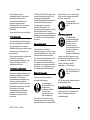
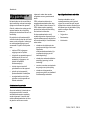
Dear Customer,
Thank you for choosing a quality
engineered STIHL product.
It has been built using modern
production techniques and
comprehensive quality assurance.
Every effort has been made to ensure
your satisfaction and trouble-free use of
the product.
Please contact your dealer or our sales
company if you have any queries
concerning this product.
Your
Dr. Nikolas Stihl
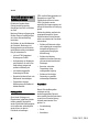
Guide to Using this Manual 26
Safety Precautions and Working
Techniques 26
Using the Unit 31
Approved Combinations of Cutting
Attachment, Deflector, Handle and
Harness 33
Mounting the Drive Tube 34
Mounting the Loop Handle 34
Mounting the Deflector 35
Mounting the Cutting Attachment 35
Mounting Depth Wheel 36
Converting Unit to Power Edger 37
Connecting to Power Supply 37
Fitting the Harness 38
Switching On 39
Switching Off 39
Overload Cutout 39
Storing the Machine 40
Maintaining the Mowing Head 40
Maintenance and Care 43
Minimize Wear and Avoid Damage 44
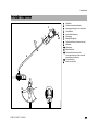
Main Parts 45
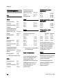
Specifications 46
Maintenance and Repairs 47
Disposal 47
EC Declaration of Conformity 47

FSE 60, FSE 71, FSE 81
English
26
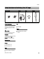
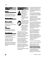
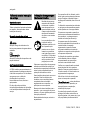
Pictograms
All the pictograms attached to the
machine are shown and explained in this
manual.
Symbols in text
WARNING
Warning where there is a risk of an
accident or personal injury or serious
damage to property.
NOTICE
Caution where there is a risk of
damaging the machine or its individual
components.
Engineering improvements
STIHL's philosophy is to continually
improve all of its products. For this
reason we may modify the design,
engineering and appearance of our
products periodically.
Therefore, some changes, modifications
and improvements may not be covered
in this manual.
Observe all applicable local safety
regulations, standards and ordinances.
If you have not used this model before:
Have your dealer or other experienced
user show you how to operate your
machine or attend a special course in its
operation.
Minors should never be allowed to use
this product.
Keep bystanders, especially children,
and animals away from the work area.
When the machine is not in use, store it
so that it does not endanger others.
Secure it against unauthorized use,
disconnect the plug from the power
supply.
The user is responsible for avoiding
injury to third parties or damage to their
property.
Do not lend or rent your unit without the
instruction manual. Be sure that anyone
using it understands the information
contained in this manual.
Persons who are not able to operate the
power tool safely due to limited physical,
sensory or mental ability may work with
it only under supervision or after being
instructed appropriately by a
responsible person.
The use of noise emitting power tools
may be restricted to certain times by
national or local regulations.
Before each use, check that your power
tool is in good condition. Pay special
attention to the power cord, mains plug
and safety devices.
Do not use the power cord to pull or
carry the power tool.
Disconnect plug from wall outlet before
performing any work on the machine,
e.g. cleaning, maintenance, replacing
parts.
The deflector on this power tool cannot
protect the operator from all objects
thrown by the cutting attachment
(stones, glass, wire, etc.). Such objects
may ricochet and then hit the operator.
Do not use a pressure washer to clean
the unit. The solid jet of water may
damage parts of the unit.
Do not spray the power tool with water.
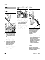
Physical Condition
To operate this power tool you must be
rested, in good physical condition and
mental health.
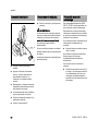
Guide to Using this Manual Safety Precautions and
Working Techniques
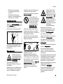
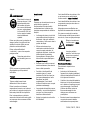
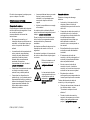
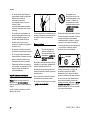
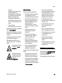
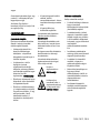
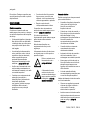
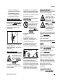
Some special safety pre-
cautions must be
observed when working
with this power tool
because of the very high
speed of its cutting
attachment and the fact
that it is powered by
electricity.
It is important that you
read the instruction man-
ual before first use and
keep it in a safe place for
future reference. Non-
observance of the
instruction manual may
result in serious or even
fatal injury.

FSE 60, FSE 71, FSE 81
English
27
If you have any condition that might be
aggravated by strenuous work, check
with your doctor before operating a
power tool.
Do not operate the power tool if you are
under the influence of any substance
(drugs, alcohol) which might impair
vision, dexterity or judgment.
Accessories and Spare Parts
Only use cutting attachments and
accessories that are explicitly approved
for this power tool by STIHL or are
technically identical. If you have any
questions in this respect, consult a
servicing dealer. Use only high quality
tools and accessories in order to avoid
the risk of accidents and damage to the
unit.
STIHL recommends the use of genuine
STIHL tools and accessories. They are
specifically designed to match the
product and meet your performance
requirements.
Never attempt to modify your machine in
any way since this may increase the risk
of personal injury. STIHL excludes all
liability for personal injury and damage
to property caused while using
unauthorized attachments.
Applications
Depending on the cutting attachment
fitted, use your trimmer only for cutting
grass, wild growth and similar materials.
Do not use the machine for any other
purpose because of the increased risk of
accidents and damage to the machine.
Never attempt to modify the product in
any way since this may result in
accidents or damage to the product.
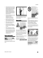
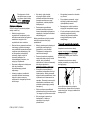
Clothing and Equipment
Wear proper protective clothing and
equipment.
Avoid clothing that could get caught on
branches or brush or moving parts of the
machine. Do not wear a scarf, necktie or
jewelry. Tie up and confine long hair
(e.g. with a hair net, cap, hard hat, etc.).
WARNING
Wear a face shield and make sure it is a
good fit. A face shield alone does not
provide adequate eye protection.
Wear hearing protection, e.g. earplugs
or ear muffs.
STIHL offers a comprehensive range of
personal protective clothing and
equipment.
Transporting the Power Tool
Always switch off the power tool and
unplug it from the power supply.
Carry the unit hanging from the shoulder
strap or properly balanced by the drive
tube or loop handle.
Transporting by vehicle: Properly secure
the power tool to prevent turnover and
damage.
Before Starting Work
Inspect the power tool.
Check that your power tool is properly
assembled and in good condition – refer
to appropriate chapters in the instruction
manual.
– Starting lockout lever and trigger
switch must move freely – the switch
must return to the idle position when
it is released.
– Use only an approved combination
of cutting attachment, deflector,
handle and harness. All parts must
be assembled properly and
securely. To reduce the risk of
injury, never use metal cutting
attachments.
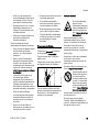
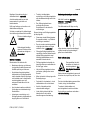
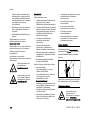
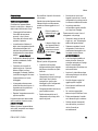
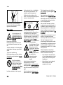
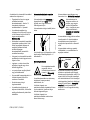
Clothing must be sturdy
but allow complete free-
dom of movement. Wear
snug-fitting clothing, an
overall and jacket combi-
nation, do not wear a
work coat.
Wear sturdy shoes with
non-slip soles.
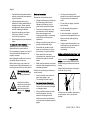
To reduce the risk of eye
injuries, wear snug-fitting
safety glasses in accord-
ance with European
Standard EN 166. Make
sure the safety glasses
are a good fit.
Wear robust work gloves
made of durable material
(e.g. leather).

FSE 60, FSE 71, FSE 81
English
28
– Check that the cutting attachment is
properly and securely mounted and
in good condition.
– Check protective devices (e.g.
deflector for cutting attachment) for
damage or wear. Always replace
damaged parts. Never operate the
unit with a damaged deflector.
– Keep the handles dry and clean –
free from oil and dirt – for safe
control of the power tool.
– Adjust handle to suit your height and
reach.
To reduce the risk of accidents, do not
operate the unit if it is not properly
assembled and in good condition.
Do not operate your power tool if any of
its components are damaged or not
properly mounted.
Never attempt to modify the controls or
the safety devices in any way.
Before switching on your power tool,
make sure the cutting attachment is not
touching the ground or any other object.
Electrical Connection.
Reduce the risk of electric shock:
– Voltage and frequency of the power
tool (see rating plate) and the
voltage and frequency of your
power supply must be the same.
– Check the connecting cord, plug
and extension cord for damage.
Never use damaged cords,
couplings and plugs or connecting
cords that do not comply with
regulations.
– Always connect the power tool to a
properly installed wall outlet.
– Check that the insulation of the
power cord, extension cord, plug
and coupling is in good condition.
– Never touch the mains plug,
connecting cord, extension cord or
electrical connections with wet
hands.
– Make sure the extension cord used
complies with the regulations for the
intended application.
Position the connecting and extension
cords correctly:
– Check minimum cross section of
wires (wire gauge) – see
"Connecting to Power Supply".
– To reduce the risk of stumbling,
position and mark the connecting
cord so that it cannot be damaged
or endanger others.
– Using unsuitable extension cords
can be dangerous. Use only
extension cords approved for
outdoor use which are labeled as
such and have the appropriate wire
gauge.
– The plug and coupling of the
extension cord must be water-proof
and must never be immersed in
water.
– Do not chafe on edges, pointed or
sharp objects
– Do not squeeze through gaps in
doors or windows
– If cords are twisted – unplug the
power tool and straighten them out
– Never touch the rotating cutting
attachment
– Always unwind the extension cord
completely from the cable drum to
reduce the risk of fire from
overheating.
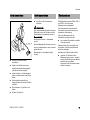
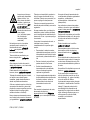
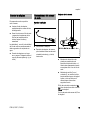
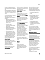
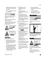
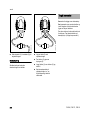
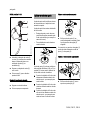
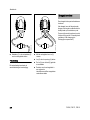
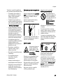
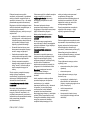
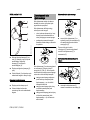
Holding and Controlling the Power Tool
Always hold the unit firmly with both
hands on the handles. Make sure you
always have good balance and secure
footing.
Always hold the machine on the right-
hand side of your body.
Left hand on loop handle, right hand on
control handle, even if you are left-
handed.
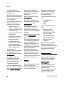
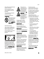
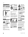
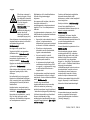
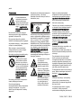
To reduce the risk of
injury, avoid contact with
the cutting attachment.
Note that the cutting
attachment continues to
run for a short period
after the power tool is
switched off – flywheel
effect.
002BA117 KN

FSE 60, FSE 71, FSE 81
English
29
During Operation
Avoid damage to the power supply cord.
Do not drive over it, pinch or tug it.
Never jerk the connecting cord to
disconnect it from the wall outlet. To
unplug, grasp the plug, not the cord.
Be sure your hands are dry before
touching the plug or power cord.
Never spray water on the unit – risk of
short circuit!
Do not leave the power tool outdoors in
the rain.
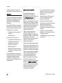
In case of imminent danger or in an
emergency, switch off the motor
immediately – release the trigger switch
and starting lockout.
Your power tool is designed to be
operated by one person only. Do not
allow other persons in the work area.
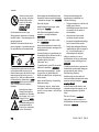
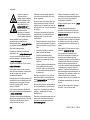
The cutting attachment may catch and
fling objects a great distance and cause
injury - therefore, do not allow any other
persons within a radius of 15 meters of
your own position. To reduce the risk of
damage to property, also maintain this
distance from other objects (vehicles,
windows). Even maintaining a distance
of 15 meters or more cannot exclude the
potential danger.
To reduce the risk of injury from thrown
objects, never operate the power tool
without the proper deflector for the type
of cutting attachment being used.
Do not cut wet grass.
Take care in slippery conditions on
slopes and uneven ground.
Keep the connecting cord behind the
power tool at all times – do not walk
backwards – risk of stumbling.
Watch out for obstacles: Roots and tree
stumps which could cause you to trip or
stumble.
Always stand on the ground while
working, never on a ladder, work
platform or any other insecure support.
Be particularly alert and cautious when
wearing hearing protection because
your ability to hear warnings (shouts,
alarms, etc.) is restricted.
To reduce the risk of accidents, take a
break in good time to avoid tiredness or
exhaustion.
Work calmly and carefully – in daylight
conditions and only when visibility is
good. Stay alert so as not to endanger
others.
Special care must be taken when
working in difficult, over-grown terrain.
When cutting high scrub, under bushes
and hedges: Keep cutting attachment at
a minimum height of 15 cm to avoid
harming small animals.
Check the cutting attachment at regular
short intervals during operation or
immediately if there is a noticeable
change in cutting behavior:
– Switch off the power tool, hold it
firmly and press the cutting
attachment into the ground to bring
it to a standstill, and disconnect the
plug from the power supply.
– Check condition and tightness, look
for cracks.
– Replace damaged cutting
attachments immediately, even if
they have only superficial cracks.
– Clean grass and plant residue off
the cutting attachment mounting at
regular intervals – remove any build
up of material from the cutting
attachment and deflector.
Always switch off the power tool and
unplug it from the power supply before
replacing the cutting attachment This
avoids the risk of injury from the motor
starting unintentionally.
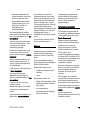
If the power supply cord
is damaged, immediately
disconnect the plug from
the wall outlet to avoid
the risk of electric shock.
The drive motor is not
waterproof. To reduce
the risk of a short circuit
or electrocution, never
work with the power tool
in the rain or in wet or
very damp locations.
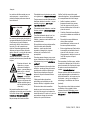
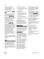
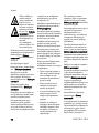
15m (50ft)
Inspect the work area:
Stones, pieces of metal
or other solid objects may
be thrown more than 15
meters and cause per-
sonal injury or damage
the cutting attachment
and property (e.g. parked
vehicles, windows).

FSE 60, FSE 71, FSE 81
English
30
Do not continue using or attempt to
repair damaged or cracked cutting
attachments by welding, straightening or
modifying the shape (out of balance).
This may cause parts of the cutting
attachment to come off and hit the
operator or bystanders at high speed
and result in serious or fatal injuries.
Use only the deflector with properly
mounted line limiting blade to ensure the
mowing lines are automatically trimmed
to the approved length.
To reduce the risk of injury, avoid
contact with the blade.
To reduce the risk of injury, always
switch off the power tool and unplug it
from the power supply before manually
adjusting the nylon line.
Using the unit with over-long nylon
cutting lines reduces the motor's
operating speed. This results in
overheating and damage to the motor.
To reduce the risk of injury, never use
wire in place of the nylon cutting line.
If your power tool is subjected to
unusually high loads for which it was not
designed (e.g. heavy impact or a fall),
always check that it is in good condition
before continuing work – see also
"Before Starting Work". Make sure the
safety devices are working properly. Do
not continue operating your power tool if
it is damaged. In case of doubt, consult
your servicing dealer.
Before leaving the power tool
unattended: Switch it off and disconnect
the plug from the power supply.
Vibrations
Prolonged use of the power tool may
result in vibration-induced circulation
problems in the hands (whitefinger
disease).
No general recommendation can be
given for the length of usage because it
depends on several factors.
The period of usage is prolonged by:
– Hand protection (wearing warm
gloves)
– Work breaks
The period of usage is shortened by:
– Any personal tendency to suffer
from poor circulation (symptoms:
frequently cold fingers, tingling
sensations).
– Low outside temperatures.
– The force with which the handles
are held (a tight grip restricts
circulation).
Continual and regular users should
monitor closely the condition of their
hands and fingers. If any of the above
symptoms appear (e.g. tingling
sensation in fingers), seek medical
advice.
Maintenance and Repairs
Always switch off the machine and
disconnect the plug from the power
supply before carrying out any
maintenance work to reduce the risk of
injury from the motor starting
unintentionally.
Service the machine regularly. Do not
attempt any maintenance or repair work
not described in the instruction manual.
Have all other work performed by a
servicing dealer.
STIHL recommends that you have
servicing and repair work carried out
exclusively by an authorized STIHL
servicing dealer. STIHL dealers are
regularly given the opportunity to attend
training courses and are supplied with
the necessary technical information.
Only use high-quality replacement parts
in order to avoid the risk of accidents
and damage to the machine. If you have
any questions in this respect, consult a
servicing dealer.
STIHL recommends the use of genuine
STIHL replacement parts. They are
specifically designed to match your
machine model and meet your
performance requirements.
Never attempt to modify your power tool
in any way since this will increase the
risk of personal injury.
Regularly check that the insulation of the
power cord and plug is in good condition
and shows no sign of ageing
(brittleness).
Electrical components, e.g. power cord,
may only be repaired or replaced by a
qualified electrician.
Clean plastic components with a cloth.
Do not use aggressive detergents. They
may damage the plastic.
Do not spray the machine with water.
Check tightness of mounting screws on
safety devices and the cutting
attachment and retighten if necessary.

FSE 60, FSE 71, FSE 81
English
31
Clean cooling air inlets in motor housing
as necessary.
Store the machine is a safe and dry
place.
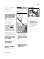
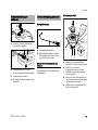
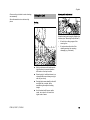
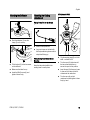
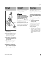
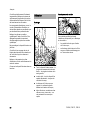
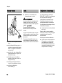
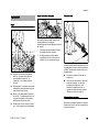
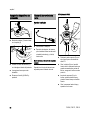
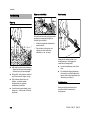
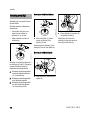
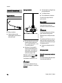
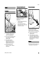
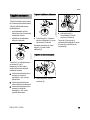
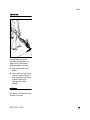
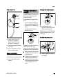
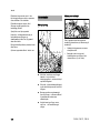
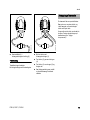
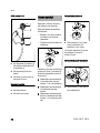
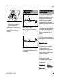
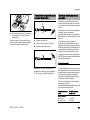
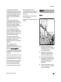
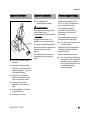
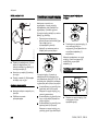
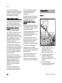
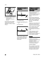
Mowing
N Hold your trimmer with both hands –
right hand on the control handle –
left hand on the loop handle.
N Stand upright – hold the trimmer in a
relaxed position and always on right
side of your body.
N Swing the trimmer steadily to the left
and right like a scythe, while
maintaining the required cutting
height.
N Avoid contact with fences, walls,
rocks, etc. since it will result in a
higher rate of wear.
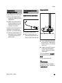
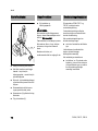
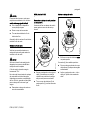
Mowing with depth wheel
A depth wheel can be quickly fitted to the
trimmer (see "Mounting Depth Wheel").
– It limits the cutting range of the
mowing line.
– It helps reduce the risk of the
rotating mowing line causing
damage (e.g. tree bark).
Using the Unit
282BA011 KN
282BA012 KN

FSE 60, FSE 71, FSE 81
English
32
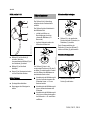
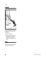
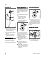
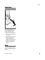
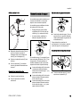
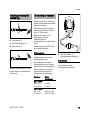
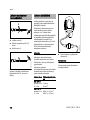
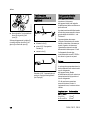
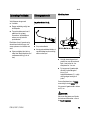
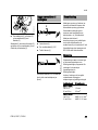
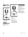
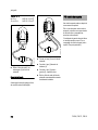
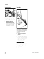
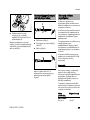
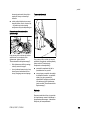
Lawn edging
The unit can be quickly converted into a
power edger (see "Converting Unit to
Power Edger").
N Use the unit as shown.
N Guide the mowing line along the
edge of the lawn – use the depth
wheel (see "Mounting Depth
Wheel") or hold the unit at the right
height.
Disposal
Do not throw cuttings into the garbage
can – they can be composted!
282BA013 KN

FSE 60, FSE 71, FSE 81
English
33
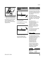
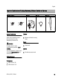
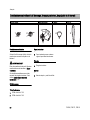
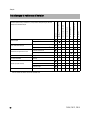
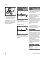
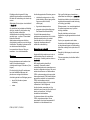
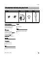
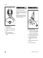
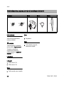
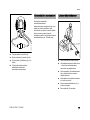
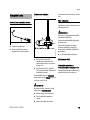
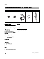
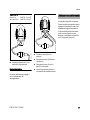
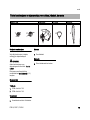
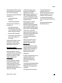
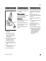
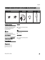
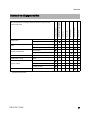
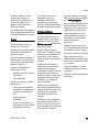
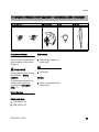
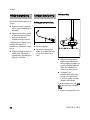
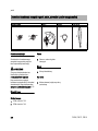
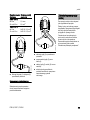
Approved Combinations
Select correct combination from the
table according to the cutting
attachment you intend to use.
WARNING
For safety reasons no other
combinations are permitted – risk of
accidents.
Only mowing heads (1, 2) may be used
on trimmers with a curved drive tube
and loop handle.
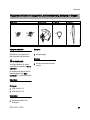
Cutting Attachments
Mowing heads
1 STIHL AutoCut C 52
2 STIHL AutoCut C 6-2
Deflector
3 Deflector with blade for mowing
heads
Handle
4 Loop handle
Harness
5 Shoulder strap may be used
Approved Combinations of Cutting Attachment, Deflector, Handle and Harness
Cutting Attachment Deflector Handle Harness
282BA010-A1
1
4
5
3
Schnur/LINE 2
Schnur/LINE 1
2

FSE 60, FSE 71, FSE 81
English
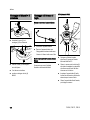
34
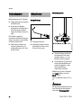
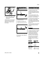
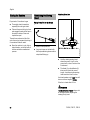
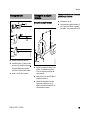
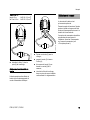
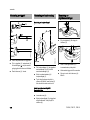
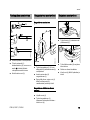
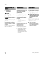
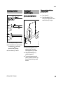
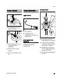
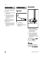
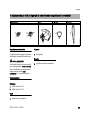
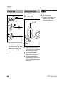
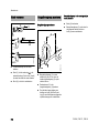
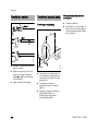
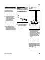
N Pull the protective cap off the drive
tube.
N Push the drive tube (1) into the
motor housing (2) as far as the mark
(A), turning the drive tube back and
forth at the same time.
N Tighten down the screw (3) in the
housing firmly.
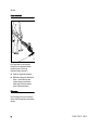
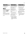
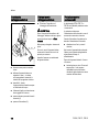
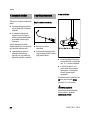
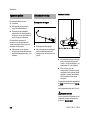
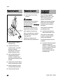
Mounting the Loop Handle
N Fit the loop handle (1) on the drive
tube at a distance A of about 30 cm
from the control handle (2).
N Insert the hex nut (3) in the loop
handle (1).
N Squeeze the ends of the clamp
together, fit the M6x40 screw (4)
with washer (5) from the other side
and tighten down firmly.
Adjusting Loop Handle to Most
Comfortable Position
N Loosen the screw (4).
N Move the loop handle (1) along the
drive tube to the required position –
tighten down the screw (4) firmly.
Mounting the Drive Tube
1
238BA016 KN
3
A
2
A
Mounting the Loop Handle
4
1
2
3
5
A
282BA001 KN
40 mm

FSE 60, FSE 71, FSE 81
English
35
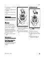
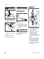
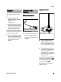
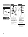
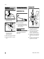
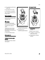
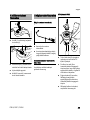
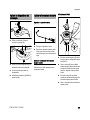
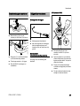
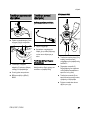
N Push the deflector (1) over the
clamp (2) as far as stop.
N Fit the locknut (3) in the hex recess
on the deflector.
N Make sure the holes line up.
N Insert the M6x30 screw (4) and
tighten it down firmly.
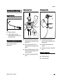
Placing Power Tool on the Ground
N Switch off the power tool.
N Lay your trimmer on its back with
the loop handle facing down and the
output shaft facing up.
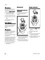
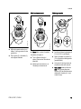
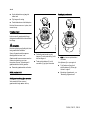
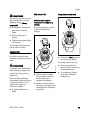
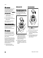
Fitting Mowing Head without Screw
Mounting
Keep the instruction leaflet for the
mowing head in a safe place.
STIHL AutoCut C 5-2
N Slip the mowing head (2) on to the
shaft – as AutoCut 5-2.
N Turn the spool (9) clockwise until
the two arrow heads line up –
secure the spool in this position.
N Insert the cap (8) in the spool, press
it down as far as stop and turn it
clockwise at the same time.
N Turn the cap until you feel
resistance and then tighten it down
firmly by hand.
Mounting the Deflector
1
238BA003 KN
2
238BA004 KN
4
3
Mounting the Cutting
Attachment
238BA021 KN
9
681BA018 KN
Schnur/LINE 2
Schnur/LINE 1
2
8

FSE 60, FSE 71, FSE 81
English
36
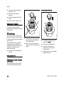
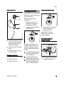
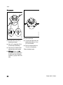
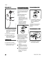
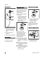
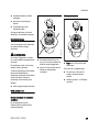
STIHL AutoCut C 6-2
N Slip the mowing head (2) over the
shaft (3) and engage its hex recess
on the external hexagon (4).
N Hold mowing head (2) steady with
one hand.
N Turn the cap (1) clockwise and
tighten it down firmly by hand.
Removing the Mowing Head
N Hold the mowing head steady.
N Unscrew the cap counterclockwise.
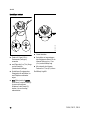
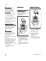
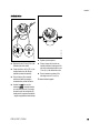
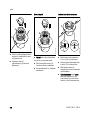
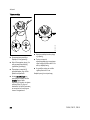
The depth wheel is included in the scope
of supply or is available as a special
accessory.
It limits the working range of the mowing
line.
– It helps reduce the risk of the
rotating mowing line causing
damage (e.g. tree bark).
– It maintains the correct ground
clearance when edging.
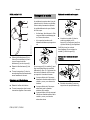
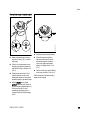
The depth wheel (1) can be locked in
three different positions (A, B or C) on
the support (2). This allows the reach of
the mowing line to be varied.
A Working range of mowing line
extends beyond the outside
diameter of the depth wheel, e.g. for
lawn edging.
B Working range of mowing line
extends up to outside diameter of
depth wheel.
C Working range of mowing line does
not reach as far as outside diameter
of depth wheel, e.g. for mowing
around trees.
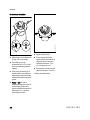
Mounting Depth Wheel on Support
N Push the depth wheel (1) into the
required position on the support (2)
until the locking hooks (3) engage.
Squeeze the locking hooks (3) together
to release the depth wheel (1) from the
support (2).
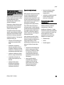
Fitting Depth Wheel on Deflector
N Push the depth wheel (1) with
support on to the deflector (4).
0000-GXX-3937-A0
2
1
3
4
Mounting Depth Wheel
3
282BA014 KN
1
2
B
C
A
3
282BA014 KN
1
2
B
C
A
1
282BA015 KN
4

FSE 60, FSE 71, FSE 81
English
37
N Secure the depth wheel (1) on the
deflector's (4) hook (6) with the
locking tab (5).
The depth wheel (1) can be released
from the hook (6) and pulled off the
deflector (4) by raising the locking
tab (5) slightly.
N Loosen the screw (1).
N Rotate the loop handle (2) 180°.
N Tighten down the screw (1) firmly.
The trimmer can now be turned through
180° and used as a power edger (see
"Applications").
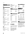
The voltage and frequency of the
machine (see rating plate) must match
the voltage and frequency of the power
connection.
The minimum fuse protection of the
power connection must comply with the
specifications – see "Specifications".
The machine must be connected to the
power supply via an earth-leakage
circuit breaker to disconnect the power
supply if the differential current to earth
exceeds 30 mA.
The power connection must correspond
to IEC 60364 and relevant national
regulations.
Extension cord
The design of the extension cord must at
least fulfill the same features as the
connecting cord on the machine.
Observe the design marking (type
designation) on the connecting cord.
The cores in the cord must have the
following minimum cross-section
depending on the mains voltage and
cord length.
5
5
6
1
282BA016 KN
4
Converting Unit to Power
Edger
1
2
282BA017 KN
282BA018 KN
Connecting to Power Supply
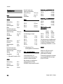
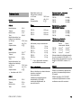
Cord length Minimum cross-
section
220 V – 240 V:
Up to 20 m 1.5 mm
2
20 m to 50 m 2.5 mm
2
100 V – 127 V:
Up to 10 m AWG 14 / 2.0 mm
2
10 m to 30 m AWG 12 / 3.5 mm
2

FSE 60, FSE 71, FSE 81
English
38
N Insert the plug (1) into the extension
cord coupling (2).
Strain Relief
The strain relief (cord retainer) protects
the appliance cord against damage.
N Make a loop (3) in the extension
cord.
N Pass the loop (3) through the
opening (4).
N Slip the loop (3) over the hook (5)
and pull it tight.
N Connect the extension cord plug to
a properly installed wall outlet.
A shoulder strap is available as a special
accessory.
Wear the shoulder strap over your left
shoulder and adjust its length so that the
spring hook lies against your right hip.
The open side of the hook should face
away from your body. Attach the spring
hook to the carrying ring (see "Main
Parts").
238BA008 KN
1
2
4
238BA009 KN
5
3
Fitting the Harness

FSE 60, FSE 71, FSE 81
English
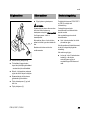
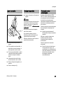
39
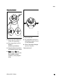
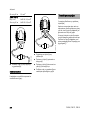
N Make sure you have a secure and
balanced footing.
N Hold your trimmer with both hands –
right hand on the control handle –
left hand on the loop handle.
N Stand upright – hold the trimmer in a
relaxed position and always on right
side of your body.
N The cutting attachment must not
touch the ground or any other
objects.
N Press down the starting lockout
lever (1) and hold it in that position.
N Squeeze the trigger switch (2).
N Release the trigger switch and
starting lockout lever.
WARNING
Note that the cutting attachment
continues to run for a short period after
you let go of the throttle trigger and
starting lockout lever – flywheel effect.
During longer work breaks – disconnect
the plug from the power supply.
When the machine is not in use, shut it
off so that it does not endanger others.
Secure it against unauthorized use.
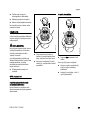
STIHL FSE 71 and FSE 81 electric
trimmers are equipped with an overload
cutout.
The overload cut out cuts off the power
supply in case of mechanical or thermal
overload.
If the overload cutout has cut off the
power supply:
N Wait about 3 minutes before
switching on again.
Do not switch on the unit during this
period because you will otherwise
prolong the required cooling time.
Once the motor starts:
N Run the unit for about 15 seconds
off load. This helps cool the motor
windings and considerably delays
renewed tripping of the overload
cutout.
Switching On
2
1
238BA010 KN
Switching Off Overload Cutout

FSE 60, FSE 71, FSE 81
English
40
For periods of 3 months or longer
N Thoroughly clean the machine,
especially the cooling air inlets.
N Take out the spool with nylon lines
and engage the ends of the lines in
the spool's notches. Clean and
inspect the spool.
The resilience and service life of the
nylon line can be increased by storing it
in a container filled with water.
N Store the machine in a dry, high or
locked location, out of the reach of
children and other unauthorized
persons.
Placing Power Tool on the Ground
N Switch off the power tool.
N Lay your trimmer on its back with
the loop handle facing down and the
output shaft facing up.
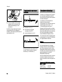
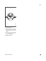
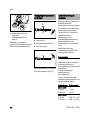
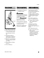
Adjusting Nylon Line
N Hold the rotating mowing head
above the ground – tap it on the
ground once – about 3 cm fresh line
is advanced.
N The blade (1) on the deflector (2)
trims surplus line to the correct
length – avoid tapping the mowing
head more than once at a time.
Line feed operates only if both lines still
have a minimum length of 2.5 cm.
If the line is shorter than 2.5 cm:
WARNING
To reduce the risk of injury, always shut
off the engine before adjusting the
mowing line by hand.
Storing the Machine Maintaining the Mowing
Head
238BA021 KN
1
232BA007 KN
2

FSE 60, FSE 71, FSE 81
English
41
N Lay your trimmer on its back, make
sure it is secure.
N Press down the cap on the spool as
far as stop.
N Pull the ends of the lines out of the
spool.
If the spool is empty, refill with nylon line.
Replacing Nylon Line
Always check the mowing head for signs
of wear before replacing the nylon line.
WARNING
If there are signs of serious wear,
replace the complete mowing head.
The nylon mowing line is referred to as
"nylon line" or "line" in the following.
The mowing head is supplied with
illustrated instructions for replacing the
nylon line. Keep the instructions for the
mowing head in a safe place.
N If necessary, remove the mowing
head.
STIHL AutoCut C 5-2
Disassembling the mowing head and
removing remaining nylon line
In normal operation, the supply of nylon
line in the head is used up almost
completely.
N Hold the mowing head steady and
rotate the cap (1) counterclockwise
until it can be removed.
N Pull the spool (2) out of the mowing
head (3) and remove the remaining
line.
Assembling the mowing head
N Fit the empty spool in the mowing
head.
If the spring (4) has popped out:
N push it into the spool (2) until it
engages in position with an audible
click.
N Mount the mowing head – see
"Mounting the Mowing Head".
Schnur/LINE 1
681BA021 KN
1
2
3
Schnur/LINE 1
681BA022 KN
2
4

FSE 60, FSE 71, FSE 81
English
42
Winding line onto spool
N Use green-coded nylon line with a
diameter of 2.0 mm (0.08 in).
N Cut two 2 m (6ft 6in) lengths of
nylon line from the reel (special
accessory).
N Rotate the spool (2)
counterclockwise until the two arrow
points are in alignment.
N Push the straight end of each line
through one sleeve (5) in the
mowing head (3) until you feel a
noticeable resistance – and then
continue pushing as far as stop.
N Hold the mowing head steady.
N Rotate the spool counterclockwise
until the shortest line is about 10 cm
(4 in).
N If necessary, cut the longer line to a
length of about 10 cm (4 in).
The mowing head is now full.
Schnur/LINE 2
681BA023 KN
5
Schnur/LINE 1
3
3
2
681BA024 KN
Schnur/LINE 2
Schnur/LINE 1

FSE 60, FSE 71, FSE 81
English
43
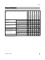
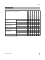
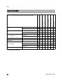
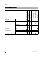
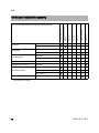
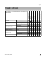
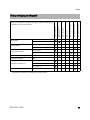
Maintenance and Care
The following intervals apply to normal operating conditions only. If your daily working time is longer or
operating conditions are difficult (very dusty work area, etc.), shorten the specified intervals
accordingly.
before starting work
after finishing work or daily
weekly
monthly
if problem
if damaged
if required
Complete machine
Visual inspection (condition) X
Clean X
Power cord
Check X
Have replaced by dealer
1)
X
Switch, starting lockout
Check operation X
Have replaced by dealer
1)
XX
Cooling inlets Clean X
All accessible screws and nuts Retighten X
Cutting attachment (mowing head)
Visual Inspection X
Replace X
Check tightness X
Safety labels Replace X
1)
STIHL recommends a STIHL servicing dealer.

FSE 60, FSE 71, FSE 81
English
44
Observing the instructions in this manual
helps reduce the risk of unnecessary
wear and damage to the power tool.
The power tool must be operated,
maintained and stored with the due care
and attention described in this
instruction manual.
The user is responsible for all damage
caused by non-observance of the safety
precautions, operating and maintenance
instructions in this manual. This includes
in particular:
– Alterations or modifications to the
product not approved by STIHL.
– Using tools or accessories which
are neither approved or suitable for
the product or are of a poor quality.
– Using the product for purposes for
which it was not designed.
– Using the product for sports or
competitive events.
– Consequential damage caused by
continuing to use the product with
defective components.
Maintenance Work
All the operations described in the
"Maintenance Chart" must be performed
on a regular basis. If these maintenance
operations cannot be performed by the
owner, they should be performed by a
servicing dealer.
STIHL recommends that you have
servicing and repair work carried out
exclusively by an authorized STIHL
servicing dealer. STIHL dealers are
regularly given the opportunity to attend
training courses and are supplied with
the necessary technical information.
If these maintenance operations are not
carried out as specified, the user
assumes responsibility for any damage
that may occur. Among other things,
this includes:
– Damage to the motor due to neglect
or deficient maintenance (e.g. not
cleaning cooling air inlets).
– Damage due to incorrect electrical
connection (voltage, inadequately
rated connecting cords).
– Corrosion and other consequential
damage resulting from improper
storage.
– Damage to the product resulting
from the use of poor quality
replacement parts.
Parts Subject to Wear and Tear
Some parts of the power tool are subject
to normal wear and tear even during
regular operation in accordance with
instructions and, depending on the type
and duration of use, have to be replaced
in good time. Among other parts, this
includes:
– Cutting attachment
– Deflector
– Carbon brushes
Minimize Wear and Avoid
Damage
Page is loading ...
Page is loading ...
Page is loading ...
Page is loading ...
Page is loading ...
Page is loading ...
Page is loading ...
Page is loading ...
Page is loading ...
Page is loading ...
Page is loading ...
Page is loading ...
Page is loading ...
Page is loading ...
Page is loading ...
Page is loading ...
Page is loading ...
Page is loading ...
Page is loading ...
Page is loading ...
Page is loading ...
Page is loading ...
Page is loading ...
Page is loading ...
Page is loading ...
Page is loading ...
Page is loading ...
Page is loading ...
Page is loading ...
Page is loading ...
Page is loading ...
Page is loading ...
Page is loading ...
Page is loading ...
Page is loading ...
Page is loading ...
Page is loading ...
Page is loading ...
Page is loading ...
Page is loading ...
Page is loading ...
Page is loading ...
Page is loading ...
Page is loading ...
Page is loading ...
Page is loading ...
Page is loading ...
Page is loading ...
Page is loading ...
Page is loading ...
Page is loading ...
Page is loading ...
Page is loading ...
Page is loading ...
Page is loading ...
Page is loading ...
Page is loading ...
Page is loading ...
Page is loading ...
Page is loading ...
Page is loading ...
Page is loading ...
Page is loading ...
Page is loading ...
Page is loading ...
Page is loading ...
Page is loading ...
Page is loading ...
Page is loading ...
Page is loading ...
Page is loading ...
Page is loading ...
Page is loading ...
Page is loading ...
Page is loading ...
Page is loading ...
Page is loading ...
Page is loading ...
Page is loading ...
Page is loading ...
Page is loading ...
Page is loading ...
Page is loading ...
Page is loading ...
Page is loading ...
Page is loading ...
Page is loading ...
Page is loading ...
Page is loading ...
Page is loading ...
Page is loading ...
Page is loading ...
Page is loading ...
Page is loading ...
Page is loading ...
Page is loading ...
Page is loading ...
Page is loading ...
Page is loading ...
Page is loading ...
Page is loading ...
Page is loading ...
Page is loading ...
Page is loading ...
Page is loading ...
Page is loading ...
Page is loading ...
Page is loading ...
Page is loading ...
Page is loading ...
Page is loading ...
Page is loading ...
Page is loading ...
Page is loading ...
Page is loading ...
Page is loading ...
Page is loading ...
Page is loading ...
Page is loading ...
Page is loading ...
Page is loading ...
Page is loading ...
Page is loading ...
Page is loading ...
Page is loading ...
Page is loading ...
Page is loading ...
Page is loading ...
Page is loading ...
Page is loading ...
Page is loading ...
Page is loading ...
Page is loading ...
Page is loading ...
Page is loading ...
Page is loading ...
Page is loading ...
Page is loading ...
Page is loading ...
Page is loading ...
Page is loading ...
Page is loading ...
Page is loading ...
Page is loading ...
Page is loading ...
Page is loading ...
Page is loading ...
Page is loading ...
Page is loading ...
Page is loading ...
Page is loading ...
Page is loading ...
Page is loading ...
Page is loading ...
Page is loading ...
Page is loading ...
Page is loading ...
Page is loading ...
Page is loading ...
Page is loading ...
Page is loading ...
Page is loading ...
Page is loading ...
Page is loading ...
Page is loading ...
Page is loading ...
Page is loading ...
Page is loading ...
Page is loading ...
Page is loading ...
Page is loading ...
Page is loading ...
Page is loading ...
Page is loading ...
Page is loading ...
Page is loading ...
Page is loading ...
Page is loading ...
Page is loading ...
Page is loading ...
Page is loading ...
Page is loading ...
Page is loading ...
Page is loading ...
Page is loading ...
Page is loading ...
Page is loading ...
Page is loading ...
Page is loading ...
Page is loading ...
Page is loading ...
Page is loading ...
Page is loading ...
Page is loading ...
Page is loading ...
Page is loading ...
Page is loading ...
Page is loading ...
Page is loading ...
Page is loading ...
Page is loading ...
Page is loading ...
Page is loading ...
Page is loading ...
Page is loading ...
Page is loading ...
Page is loading ...
Page is loading ...
Page is loading ...
Page is loading ...
Page is loading ...
Page is loading ...
Page is loading ...
Page is loading ...
Page is loading ...
Page is loading ...
Page is loading ...
Page is loading ...
Page is loading ...
Page is loading ...
Page is loading ...
Page is loading ...
Page is loading ...
Page is loading ...
Page is loading ...
Page is loading ...
Page is loading ...
Page is loading ...
Page is loading ...
Page is loading ...
Page is loading ...
Page is loading ...
Page is loading ...
Page is loading ...
Page is loading ...
Page is loading ...
Page is loading ...
Page is loading ...
Page is loading ...
Page is loading ...
Page is loading ...
Page is loading ...
Page is loading ...
Page is loading ...
Page is loading ...
Page is loading ...
Page is loading ...
Page is loading ...
Page is loading ...
Page is loading ...
Page is loading ...
Page is loading ...
Page is loading ...
Page is loading ...
Page is loading ...
Page is loading ...
Page is loading ...
Page is loading ...
Page is loading ...
Page is loading ...
Page is loading ...
Page is loading ...
Page is loading ...
Page is loading ...
Page is loading ...
Page is loading ...
Page is loading ...
Page is loading ...
Page is loading ...
Page is loading ...
Page is loading ...
Page is loading ...
Page is loading ...
Page is loading ...
Page is loading ...
Page is loading ...
Page is loading ...
Page is loading ...
Page is loading ...
Page is loading ...
Page is loading ...
Page is loading ...
Page is loading ...
Page is loading ...
Page is loading ...
Page is loading ...
Page is loading ...
Page is loading ...
Page is loading ...
Page is loading ...
Page is loading ...
Page is loading ...
Page is loading ...
Page is loading ...
-
 1
1
-
 2
2
-
 3
3
-
 4
4
-
 5
5
-
 6
6
-
 7
7
-
 8
8
-
 9
9
-
 10
10
-
 11
11
-
 12
12
-
 13
13
-
 14
14
-
 15
15
-
 16
16
-
 17
17
-
 18
18
-
 19
19
-
 20
20
-
 21
21
-
 22
22
-
 23
23
-
 24
24
-
 25
25
-
 26
26
-
 27
27
-
 28
28
-
 29
29
-
 30
30
-
 31
31
-
 32
32
-
 33
33
-
 34
34
-
 35
35
-
 36
36
-
 37
37
-
 38
38
-
 39
39
-
 40
40
-
 41
41
-
 42
42
-
 43
43
-
 44
44
-
 45
45
-
 46
46
-
 47
47
-
 48
48
-
 49
49
-
 50
50
-
 51
51
-
 52
52
-
 53
53
-
 54
54
-
 55
55
-
 56
56
-
 57
57
-
 58
58
-
 59
59
-
 60
60
-
 61
61
-
 62
62
-
 63
63
-
 64
64
-
 65
65
-
 66
66
-
 67
67
-
 68
68
-
 69
69
-
 70
70
-
 71
71
-
 72
72
-
 73
73
-
 74
74
-
 75
75
-
 76
76
-
 77
77
-
 78
78
-
 79
79
-
 80
80
-
 81
81
-
 82
82
-
 83
83
-
 84
84
-
 85
85
-
 86
86
-
 87
87
-
 88
88
-
 89
89
-
 90
90
-
 91
91
-
 92
92
-
 93
93
-
 94
94
-
 95
95
-
 96
96
-
 97
97
-
 98
98
-
 99
99
-
 100
100
-
 101
101
-
 102
102
-
 103
103
-
 104
104
-
 105
105
-
 106
106
-
 107
107
-
 108
108
-
 109
109
-
 110
110
-
 111
111
-
 112
112
-
 113
113
-
 114
114
-
 115
115
-
 116
116
-
 117
117
-
 118
118
-
 119
119
-
 120
120
-
 121
121
-
 122
122
-
 123
123
-
 124
124
-
 125
125
-
 126
126
-
 127
127
-
 128
128
-
 129
129
-
 130
130
-
 131
131
-
 132
132
-
 133
133
-
 134
134
-
 135
135
-
 136
136
-
 137
137
-
 138
138
-
 139
139
-
 140
140
-
 141
141
-
 142
142
-
 143
143
-
 144
144
-
 145
145
-
 146
146
-
 147
147
-
 148
148
-
 149
149
-
 150
150
-
 151
151
-
 152
152
-
 153
153
-
 154
154
-
 155
155
-
 156
156
-
 157
157
-
 158
158
-
 159
159
-
 160
160
-
 161
161
-
 162
162
-
 163
163
-
 164
164
-
 165
165
-
 166
166
-
 167
167
-
 168
168
-
 169
169
-
 170
170
-
 171
171
-
 172
172
-
 173
173
-
 174
174
-
 175
175
-
 176
176
-
 177
177
-
 178
178
-
 179
179
-
 180
180
-
 181
181
-
 182
182
-
 183
183
-
 184
184
-
 185
185
-
 186
186
-
 187
187
-
 188
188
-
 189
189
-
 190
190
-
 191
191
-
 192
192
-
 193
193
-
 194
194
-
 195
195
-
 196
196
-
 197
197
-
 198
198
-
 199
199
-
 200
200
-
 201
201
-
 202
202
-
 203
203
-
 204
204
-
 205
205
-
 206
206
-
 207
207
-
 208
208
-
 209
209
-
 210
210
-
 211
211
-
 212
212
-
 213
213
-
 214
214
-
 215
215
-
 216
216
-
 217
217
-
 218
218
-
 219
219
-
 220
220
-
 221
221
-
 222
222
-
 223
223
-
 224
224
-
 225
225
-
 226
226
-
 227
227
-
 228
228
-
 229
229
-
 230
230
-
 231
231
-
 232
232
-
 233
233
-
 234
234
-
 235
235
-
 236
236
-
 237
237
-
 238
238
-
 239
239
-
 240
240
-
 241
241
-
 242
242
-
 243
243
-
 244
244
-
 245
245
-
 246
246
-
 247
247
-
 248
248
-
 249
249
-
 250
250
-
 251
251
-
 252
252
-
 253
253
-
 254
254
-
 255
255
-
 256
256
-
 257
257
-
 258
258
-
 259
259
-
 260
260
-
 261
261
-
 262
262
-
 263
263
-
 264
264
-
 265
265
-
 266
266
-
 267
267
-
 268
268
-
 269
269
-
 270
270
-
 271
271
-
 272
272
-
 273
273
-
 274
274
-
 275
275
-
 276
276
-
 277
277
-
 278
278
-
 279
279
-
 280
280
-
 281
281
-
 282
282
-
 283
283
-
 284
284
-
 285
285
-
 286
286
-
 287
287
-
 288
288
-
 289
289
-
 290
290
-
 291
291
-
 292
292
-
 293
293
-
 294
294
-
 295
295
-
 296
296
-
 297
297
-
 298
298
-
 299
299
-
 300
300
-
 301
301
-
 302
302
-
 303
303
-
 304
304
-
 305
305
-
 306
306
-
 307
307
-
 308
308
-
 309
309
-
 310
310
-
 311
311
-
 312
312
-
 313
313
-
 314
314
-
 315
315
-
 316
316
-
 317
317
-
 318
318
-
 319
319
-
 320
320
-
 321
321
-
 322
322
-
 323
323
-
 324
324
-
 325
325
-
 326
326
-
 327
327
-
 328
328
-
 329
329
-
 330
330
-
 331
331
-
 332
332
-
 333
333
-
 334
334
-
 335
335
-
 336
336
-
 337
337
-
 338
338
-
 339
339
-
 340
340


STIHL FSE 60, 71, 81 Owner's manual
- Category
- Grass trimmers
- Type
- Owner's manual
- This manual is also suitable for
Ask a question and I''ll find the answer in the document
Finding information in a document is now easier with AI
in other languages
- italiano: STIHL FSE 60, 71, 81 Manuale del proprietario
- français: STIHL FSE 60, 71, 81 Le manuel du propriétaire
- español: STIHL FSE 60, 71, 81 El manual del propietario
- Deutsch: STIHL FSE 60, 71, 81 Bedienungsanleitung
- Nederlands: STIHL FSE 60, 71, 81 de handleiding
- português: STIHL FSE 60, 71, 81 Manual do proprietário
- dansk: STIHL FSE 60, 71, 81 Brugervejledning
- polski: STIHL FSE 60, 71, 81 Instrukcja obsługi
- svenska: STIHL FSE 60, 71, 81 Bruksanvisning
- suomi: STIHL FSE 60, 71, 81 Omistajan opas
Related papers
Other documents
-
Texas RT 5000 Operating Instructions Manual
-
-
ABB FSE-31 Quick Manual
-
BLACK DECKER GL315 Owner's manual
-
Gardenline 17505 Translation Of The Original Instructions
-
Zipper Mowers ZI-MOS100-4T Operating instructions
-
Ferm LTM1006 User manual
-
BLACK DECKER GL650 Owner's manual
-
BLACK DECKER ST5530 Owner's manual
-