Christopeit EM 3 Owner's manual
- Category
- Spin bikes
- Type
- Owner's manual
This manual is also suitable for

1
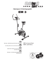
Heimsport-Trainingsgerät
EM 3
Montage- und Bedienungsanleitung für Bestell-Nr.
Notice de montage et d’utilisation du
No. de commande
Assembly and exercise instructions for Order No.
Montage- en bedieningshandleiding voor
Bestellnummer
GB
D
F
NL
9808 (schwarz/silber)
98081 (weiß/türkis)
Page is loading ...
Page is loading ...
Page is loading ...
Page is loading ...
Page is loading ...
Page is loading ...
Page is loading ...
Page is loading ...
Page is loading ...
Page is loading ...
Page is loading ...

13
Contents
1. Summary of Parts Page 3 - 4
2. Important Recommendations and Safety Information Page 13
3. Parts List Page 14 - 15
4. Assembly Instructions With Exploded Diagrams Page 16 - 17
5. Computer instructions Page 19 - 21
6. Training Instructions Page 22
Dear customer,
We congratulate you on your purchase of this home training sports unit and
hope that we will have a great deal of pleasure with it. Please take heed of
the enclosed notes and instructions and follow them closely concerning
assembly and use.
Please do not hesitate to contact us at any time if you should have any
questions.
Top-Sports Gilles GmbH
GB
Important Recommendations and
Safety Instructions
Our products are all TÜV-GS tested and therefore represent the highest
current safety standards. However, this fact does not make it unnecessary
to observe the following principles strictly.
1. Assembly the machine exactly as described in the installation instructions
and use only the enclosed, specific parts of the machine contained in the
parts list. Before assembling, verify the completeness of the delivery against
the delivery notice and the completeness of the carton against the parts list
in the installation and operating instructions.
2. Check the firm seating off all screws, nuts and other connections before
using the machine for the first time and at regular intervals to ensure that
the trainer is in a safe condition.
3. Set up the machine in a dry, level place and protect it from moisture and
water. Uneven parts of the floor must be compensated by suitable measures
and by the provided adjustable parts of the machine if such are installed.
Ensure that no contact occurs with moisture or water.
4. Place a suitable base (e.g. rubber mat, wooden board etc.) beneath the
machine if the area of the machine must be specially protected against
indentations, dirt etc.
5. Before beginning training, remove all objects within a radius of 2 metres
from the machine.
6. Do not use aggressive cleaning agents to clean the machine and employ
only the supplied tools or suitable tools of your own to assemble the machine
and for any necessary repairs. Remove drops of sweat from the machine
immediately after finishing training.
7. Your health can be impaired by incorrect or excessive training. Consult
a doctor before beginning a planned training programme. He can define
the maximum exertion (pulse, Watts, duration of training etc.) to which you
may expose yourself and can give you precise information on the correct
posture during training, the targets of your training and your diet. Never
train after eating large meals.
8. Only train on the machine when it is in correct working order. Use original
spare parts only for any necessary repairs.
9. When setting the adjustable parts, observe the correct position and the
marked, maximum setting positions and ensure that the newly adjusted
position is correctly secured.
10. Unless otherwise described in the instructions, the machine must only
be used for training by one person at a time.
11. Wear training clothes and shoes which are suitable for fitness training
with the machine. Your clothes must be such that they cannot catch dur-
ing training due to their shape (e.g. length). Your training shoes should be
appropriate for the trainer, must support your feet firmly and must have
non-slip soles.
12. If you notice a feeling of dizziness, sickness, chest pain or other abnormal
symptoms, stop training and consult a doctor.
13. Never forget that sports machines are not toys. They must therefore
only be used according to their purpose and by suitably informed and
instructed persons.
14. People such as children, invalids and handicapped persons should
only use the machine in the presence of another person who can give aid
and advice. Take suitable measures to ensure that children never use the
machine without supervision.
15. Ensure that the person conducting training and other people never move
or hold any parts of their body into the vicinity of moving parts.
16. At the end of its life span this product is not allowed to dispose over
the normal household waste, but it must be given to an assembly point for
the recycling of electric and electronic components. You may find the symbol
on the product, on the instructions or on the packing.
The materials are reusable in accordance with their marking. With the re-use,
the material utilization or the protection of our environment. Please ask the
local administration for the responsible disposal place.
17. This machine is a speed-independant machine.
18. The unit has a resistance device with 16 levels. This makes it possible
to increase or reduce the braking resistance and thus the amount of effort
required in the training. Pressing the button with an arrow pointing upwards
reduces the braking resistance and thus the amount of effort required in the
training. Pressing the button with an arrow pointing downwards increases
the braking resistance and thus the amount of effort required in the training.
19. This machine has been tested and certified in compliance with EN 957-1
and –5 “H,A”. The maximum permissible load (=body weight) is specified
as 150 kg.
English

14
Please check after opening the packing that all the parts shown in
the following parts lists are there. Once you are sure that this is the
case, you can start assembly.
Please contact us if any components are defective or missing, or if
you need any spare parts or replacements in future:
Adresse: Top-Sports Gilles GmbH
Friedrichstr. 55
42551 Velbert
Telefon: +49 (0) 20 51 - 6 06 70
Telefax: +49 (0) 20 51 - 6 06 74 4
e-mail: [email protected]
www.christopeit-sport.com
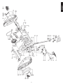
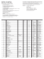
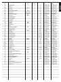
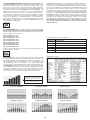
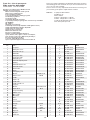
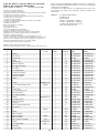
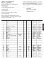
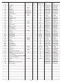
Parts list – List of spare parts
EM 3 order No. 9808, 98081
Technical data: Issue: 01. 10. 2009
Ergometer according to Class EN 957-1/5 H/A
with high precision indicator.
Motor-controlled magnetic brake system
Approx. 9 kg centrifugal mass
6 stored training programs
3 stored heart frequency training programs
4 individual programmes
1 body fat program
16 manually adjustable load steps
1 speed independent program (power control in steps of 10 Watt
(30-300 Watt))
AC- adapter
Hand pulse measurement
horizontally and vertically adjustable saddle (quick release)
Saddle and handlebar inclination adjustable
Saddle universal exchangeable
Transport rollers at front foot
Drink bottle with bottle rack
Floor level compensation
Training computer with digital display of:
speed, distance, time, approx. calorie consumption,
pulse frequency, pulse rate, Watts, Body fat analyse,
Recovery and program profiles.
Load max. 150 kg (Body weight)
Space requirement approx. L 110 x B 52 x H 148 cm
Illustration Designation Dimensions Quantity Attached to ET number ET number
No. mm illustration No. 9808 98081
1 Computer 1 7 36-9808-03-BT 36-9808103-BT
2 Hand pulse sensor 2 4 36-9613204-BT 36-9613204-BT
3 Handlebar end cap 2 4 39-9847 39-9847
4 Handlebar 1 11 33-9808-07-SI 33-9808107-WS
5 Hand pulse cable 1 1+2 36-9613205-BT 36-9613205-BT
6 Connection cable 1 1+26 36-9808-05-BT 36-9808-05-BT
7 Handlebar post 1 27 33-9808-02-SI 33-9808102-WS
8 Handlebar Adjusting knob 1 11 36-9613210-BT 36-9613210-BT
9 Bushing 1 8 36-9613209-BT 36-9613209-BT
10 Handlebar shield cover 1 11 36-9613208-BT 36-9613208-BT
11 Handlebar holder 1 7 33-9613208-SI 33-9808108-WS
12 Bottle holder 1 7 36-9913123-BT 36-9913123-BT
13 Bottle 1 12 36-9913122-BT 36-9913122-BT
14 Self-tapping screw 2 12 36-9210-30-BT 36-9210-30-BT
15 Washer Ø20xØ8.2x1.2T 4 16 39-9864-VC 39-9864-VC
16 Button screw M8x20 4 7 39-9886-CR 39-9886-CR
17 Saddle 1 19 36-9913106-BT 36-9913106-BT
18 Square cap 2 19 39-9954 39-9954
19 Saddle slide 1 21 33-9913103-SI 33-9808106-WS
20 Saddle movable set 1 19 36-9913107-BT 36-9913107-BT
21 Seat post 1 27 33-9808-05-SI 33-9808105-WS
22 Washer Ø 20x Ø 10.2x1.5T 1 23 39-10207 39-10207
23 Adjust knob M 10 1 20 36-9814-14-BT 36-9814-14-BT
24 Seat post bushing 1 27 36-9808-06-BT 36-9808-06-BT
25 Rubber cover 1 63 36-9808-07-BT 36-9808-07-BT
26 Motor cable 1 6 36-9808-08-BT 36-9808-08-BT
27 Main frame 1 33-9808-01-SI 33-9808101-WS
28 Bolt M5x20 9 1+30+63 39-10190 39-10190
29 Sensor 1 27 36-9808-09-BT 36-9808-09-BT
30 Sensor holder 1 29 36-9808-10-BT 36-9808-10-BT
31 Bearing 6203Z 2 27+37 39-9999 39-9999
32 C-Clip Ø 17 2 37 36-9504-20-BT 36-9504-20-BT
33 Pulley Ø 220 1 37 36-9808-11-BT 36-9808-11-BT
34 Washer Ø18xØ6.2x1.0 6 38+54 39-9993 39-9993
35 Nylon nut M 6 6 38 39-9816-VC 39-9816-VC
36 Magnets 1 33 36-9613222-BT 36-9613222-BT
37 Crank axle 1 31 33-9808-08-SI 33-9808-08-SI

15
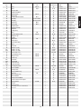
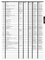
Illustration Designation Dimensions Quantity Attached to ET number ET number
No. mm illustration No. 9808 98081
38 Bolt M6x15 4 37 39-9911 39-9911
39 Belt 370J 1 33+52 36-9808-12-BT 36-9808-12-BT
40 Console wire 1 41 36-9808-13-BT 36-9808-13-BT
41 Adjustment Motor 1 27 36-9808-14-BT 36-9808-14-BT
42 Motor Screw M5x13 4 41 39-9903-SW 39-9903-SW
43 Motor wire 1 41 36-9808-15-BT 36-9808-15-BT
44 Saddle adjustment knob M14 1 27 36-9613220-BT 36-9613220-BT
45 Bushing Ø 14x1.5Tx6L 1 49 36-9913111-BT 36-9913111-BT
46 Bushing Ø 14x1.5Tx11L 2 49 36-9613227-BT 36-9613227-BT
47 Nylon Nut M10 3 49 39-9930-SW 39-9930-SW
48 Flange Nut M10 2 49 39-10256 39-10256
49 Flywheel Axle 1 50 33-9808-12-SI 33-9808-12-SI
50 Flywheel bearing 4 51 36-9808-16-BT 36-9808-16-BT
51 Flywheel 1 50 33-9808-14-SI 33-9808-14-SI
52 Small pulley 1 49 33-9808-06-SI 33-9808-06-SI
53 Bolt M6 2 54 39-9816-VC 39-9816-VC
54 Double tapping screw Ø6x75 1 27+55 36-9913117-BT 36-9913117-BT
55 Magnetic clip 1 54 33-9808-13-SI 33-9808-13-SI
56 Spring 1 55 36-9913119-BT 36-9913119-BT
57 Nylon Nut M8 2 60 39-9918-CR 39-9918-CR
58 Plat washer 6 60+72 39-10018-CR 39-10018-CR
59 Idler arm bearing 2 61 36-9808-17-BT 36-9808-17-BT
60 Bolt M8x25 1 27+61 39-10455 39-10455
61 Idler arm 1 62 33-9808-09-SI 33-9808-09-SI
62 Magnets spring 1 27+61 36-9808-18-BT 36-9808-18-BT
63L Chain cover left 1 27+63R 36-9808-01-BT 36-9808101-BT
63R Chain cover right 1 27+63L 36-9808-02-BT 36-9808102-BT
64 Side shield cover 1 63L+63R 36-9808-04-BT 36-9808104-BT
65 Self-tapping screw M4x10 4 64 39-10185 39-10185
66 Flange screw M8x20 2 37 39-9886-CR 39-9886-CR
67 Crank cap 2 69 36-9840-15-BT 36-9840-15-BT
68L Pedal left 1 69L 36-9913120-BT 36-9913120-BT
68R Pedal right 1 69R 36-9913121-BT 36-9913121-BT
69L Crank arm left 1 37 33-9808-10-SW 33-9808-10-SW
69R Crank arm right 1 37 33-9808-11-SW 33-9808-11-SW
70 self-tapping screw M5x20 9 63L+63R 39-10190 39-10190
71 Front stabilizer 1 27 33-9808-03-SI 33-9808103-WS
72 Carriage bolt M8x60 4 71+76 39-10094-CR 39-10094-CR
73 Front stabilizer Cap 2 71 36-9808-19-BT 36-9808-19-BT
74 Cap nut M8 4 72 39-9900-VC 39-9900-VC
75 Rear stabilizer Cap 2 76 36-9808-20-BT 36-9808-20-BT
76 Rear stabilizer 1 27 33-9808-04-SI 33-9808104-WS
77 Adapter 6V=//1000mA 1 78 36-9808-21-BT 36-9808-21-BT
78 Connect wire for AC adapter 1 77 36-9808-22-BT 36-9808-22-BT
79 Spring washer For M8 8 16+72 39-9864-VC 39-9864-VC
80 Carton 1 36-9808-23-BT 36-9808-23-BT
81 Carton sticker 1 36-9808-24-BT 36-9808105-BT
82 Assembly & exercise instructions 1 36-9808-27-BT 36-9808-27-BT
83 Tool set 1 36-9808-26-BT 36-9808-26-BT
English

16
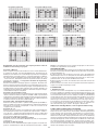
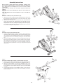
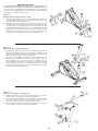
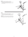
Assembly Instructions
Remove all the separate parts from the packaging, lay them on the
floor and check that all are there on the basis of the step drawings in
these instructions for assembly and use. Please note that a number
of parts have
been connected directly to the main frame and preassembled. In
addition,
there are several other individual parts that have been attached to
separate
units. This will make it easier and quicker for you to assemble the
equipment.
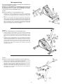
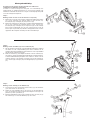
Step 1:
Attach the stabilizer (71+76) at main frame (27).
1. Attach the front foot (71) with the preassembled transport rollers (73) to
the main frame. Do this with the two screws (72), washers (58), spring
washers (79) and cap nuts (74).
2. Attach the rear foot (76) to the main frame (27). Do this with the two
screws (72), washers (58), spring washers (79) and cap nuts (74).
After assembly has been completed, you can compensate for minor
irregularities in the floor by turning the adjusting screw of end cap (75).
The equipment should be set up that the equipment does not move of
its own accord during a training session.
Step 2:
Attach the front post (7) at main frame (27).
1. Hold the handlebar support (7) with the computer cable (6) Against the
main frame holder. Connect the plug for the computer cable (6) coming
out of the bottom of the handlebar support (7) of the computer with the
matching plug for the motor cable (26) coming out of the main frame
(27).
2. Place the handlebar support (7) in the locator provided for it in the main
frame (27). Ensure that the cable connections made are not squashed.
When putting the steering tube in place, push the former slowly down
into the locator in the main frame. Screw the handlebar support (7)
onto the base frame (27) with the screws (16), spring washers (79) and
washers (15).
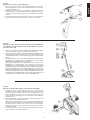
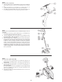
Step 3:
Attach the handlebar (4) and bottle (13) at handlebar support (7).
1. Guide the preassembled handlebar unit (4) through the upper part of
the handlebar post (7) and close the bracket of handlebar holder (11).
2. Attach the front handlebar cover (10) at the handlebar holder (11) of
handlebar support (7) and screw the handlebar (4) in desired position at
the handlebar post (7) and tighten firmly with spacer (9) and handlebar
screw (8).
3. Put the bottle holder (12) at the handlebar support (7); fix it with two
screws (14) at appropriate position and insert the bottle (13) into the
bottle holder (12).

17
English
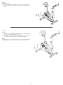
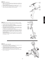
Step 4:
Attach the computer (1) at handlebar support (7).
1. Push the plug of the connecting cable (6) projecting from the handlebar
support (7) into the associated socket of the computer (1).
2. Place the computer on the plate provided for it on the handlebar support
(7) and attach it with the screws (28).
3. Push the plug of the pulse cable (5) projecting from the handlebar (4)
into the associated socket of the computer (1).
Step 5:
Installation of saddle (17) at saddle support (21) by using saddle slide
(19). Installation of saddle support (21) at mainframe by using rapid
action lock (44).
1. Push the saddle (17) with saddle bracket into the movable saddle slide
(19) and tight it up in desired position.
2. Place the movable seat post (19) into the holder of saddle post (21), set
it at the desired horizontally position and tighten it by washer (22) and
movable seat knob (23).
3. Insert the saddle support (12) into the provided holder of the main frame
(27) and secure at the desired position by screwing in the rapid-action
lock (44).
(Note: To screw in the rapid-action lock (44), the threaded hole in the
main frame (27) and one of the holes in the saddle support (21) must be
aligned. Furthermore, ensure that the saddle support (21) is not pulled
out of the main frame beyond the marked maximum Position. The setting
of the saddle post can be adjusted as desired later. For this, the rapid
action catch (44) must be loosened by only a few revolutions, the cap
of the lock must be pulled away and the saddle adjusted. Then secure
the new setting by tightening the rapid action catch.
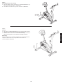
Step 6:
Installation of the right pedal (68R) and the left pedal (68L) on the
pedal arms (69R+69L).
1. The pedals are marked „R“ for right and „L“ for left.
2. Screw the right pedal (68R) into the threaded hole on the right hand side
of the pedal arm (69R) and tighten firmly.
(Note: Right and left are specified as viewed seated on the machine
during training. It must also be observed that the threaded part of the
right pedal must be screwed clockwise into the threaded hole of the
pedal crank.)
3. Screw the left pedal (68L) into the threaded hole on the left hand side
of the pedal arm (68L) and tighten firmly.
(Note: The threaded part of the left pedal must be screwed anticlockwise
into the threaded hole of the pedal crank.)
4. Then attach the pedal straps left and right to the respective pedals.

18
Step 8:
Checks
1. Check the correct installation and function of all screwed and plug
connections. Installation is thereby complete.
2. When everything is in order, familiarise yourself with the machine at a
low resistance setting and make your individual adjustments.
Note:
Please keep the tool set and the instructions in a safe place as these may
be required for repairs or spare parts orders becoming necessary later.
Step 7:
Attach the power.
1. Please insert the plug of adaptor (77) to the jack of chain guard (78).
2. Please insert the plug of adaptor (77) to the jack of wall power (230V-
50Hz).

19
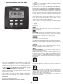
Computer Instructions for 9808, 98081
The monitor is designed for programmable magnetic bikes and
introduced with the following categories:
- Key Functions
- About Displays
- Operating Ranges
- Things You Should Know Before Exercising
- Operation Instructions
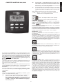
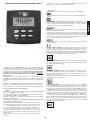
• KeyFunctions
There are total 6 keys including START/STOP(S), ENTER/
EINGABE(E), MODE/AUSWAHL(F), UP/AUF(+), DOWN/AB(-), and
RECOVERY/ERHOLUNGSPULS(TEST).
A. START/STOP(S): Starts or stops the program chosen. And,
resets the monitor by pressing and holding for 2 seconds.
B. ENTER/EINGABE(E): Chooses the functions from PROGRAMS,
GENDER, TIME, HEIGHT, WEIGHT, DISTANCE, WATT, TARGET
HEART RATE, AGE, and 10 columns. The chosen function shall
flash. Please note that not all the functions can be selected in
every program according to the types of each program.
C. MODE/AUSWAHL(F): Changes the displays of the values
between RPM or SPEED, and KJOULE/CAL or WATT. The
values of RPM and WATT show at the same time, or the values
of SPEED and KJOULE/CAL do by pressing it.
D. UP/AUF(+): Selects or increases the values of PROGRAMS,
GENDER, TIME, HEIGHT, WEIGHT, DISTANCE, WATT, TARGET
HEART RATE, AGE, and 10 columns.
E. DOWN/AB(-): Selects or decreases the values of PROGRAMS,
GENDER, TIME, HEIGHT, WEIGHT, DISTANCE, WATT, TARGET
HEART RATE, AGE, and 10 columns.
F. RECOVERY/ERHOLUNGSPULS(TEST): Starts the function of
PULSE RECOVERY.
•AboutDisplay
A.
START: Indicates the program selected has started.
B.
STOP: Indicates the program selected has stopped. And, users
are free to change the programs and the value of functions
applied.
C.
PROGRAM: Indicates the programs selected from
PROGRAM 1 to PROGRAM 17
D. LEVEL: Indicates the level of loading selected from LEVEL 1 to LEVEL
16.
E.
GENDER: Indicates the gender (Male or Female) selected.
F.
TIME/HEIGHT/WEIGHT Display: Indicates only 1 value of TIME, HEIGHT,
or WEIGHT displayed depending on the programs.
G. RPM/SPEED/KMH (MPH) Display: Indicates only 1 value of
RPM, SPEED, or KMH (MPH) displayed depending on the programs.
H. DISTANCE/FAT% Display: Indicates only 1 value of DISTANCE
or FAT% displayed depending on the programs.
I. CAL/WATT/BMR Display: Indicates only one value of CAL,
WATT, or BMR displayed depending on the programs.
J. TARGET H.R./BMI/AGE Display: Indicates only one value
of TARGET HEART RATE, BMI, or AGE displayed depending on the
programs.
K. HEART RATE/BODY TYPE Display: Indicates only one value of
HEART RATE or BODY TYPE displayed depending on the programs.
L.
LOADING Profiles: There are 10 columns of loading bars, and 8 bars in
each column. Each column represents 3 minutes workout (without the
change of TIME value), and each bar represents 2 levels of loading.
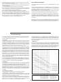
•OperatingRanges
• Things You Should Know Before Exercising
A. The values calculated or measured by the computer are for exercise
purpose only, not for medical purpose.
B. The Variables May Need To Change In The Programs:
Please note that only 1 value of TIME or DISTANCE can be adjusted.
Both adjustments do not exist at the same time. For example, the value
of DISTANCE is „0.0“ while the value of TIME is adjusted to be any
number except „00:00“.
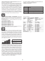
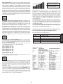
Values Range (Count up) Count down Preset Increment (Decrement)
PROGRAM 1 ~ 17 17 ~ 1 1 1
LEVEL 1 ~ 16 16 ~ 1 N/A 1
GENDER Male, Female N/A Male N/A
TIME 0:00 ~ 99:59 99:00 ~ 5:00 0:00 1:00
HEIGHT (cm) 110.0 ~ 199.5 199.5 ~ 110.0 175.0 0.5
WEIGHT (kg) 10.0 ~ 199.8 199.8 ~ 10.0 70.0 0.2
DISTANCE 0.0 ~ 999.0 999.0 ~ 1.0 0.0 1.0
WATT 30 ~ 300 300 ~ 30 100 10
TARGET H.R. 60 ~ 220 220 ~ 60 90 1
AGE 10 ~ 99 99 ~ 10 30 1
English

20
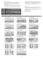
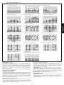
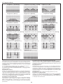
Program 1 (Manual) Program 2 (Polling) Program 3 ( Valley )
Program ( Fat Burn ) Program 5 (Ramp) Program 6 (Mountain)
Program 7 (Random) Program 8 (Body Fat) Program 9 (Target H.R.)
Program 10 (60% H.R.C.) Program 11 (75% H.R.C.) Program 12 (85% H.R.C.)
Program 13 (User Setting) Program 14 (User Setting) Program 15 (User Setting)
Program 16 (User Setting) Program 17 (Watt Control)
Programs Variables
P1 - P7 TIME, DISTANCE, AGE
P8 GENDER, HEIGHT, WEIGHT, AGE
P9 TIME, DISTANCE, TARGET H.R.
P10 - P12 TIME, DISTANCE, AGE
P13 - P16 TIME, DISTANCE, AGE, 10 INTERVALS
P17 TIME, DISTANCE, WATT, AGE
C. Programs Selection:
There are 17 programs with 1 Recovery including 1 Manual
Program, 6 Preset Programs, 1 Body Fat Program, 4 Heart
Rate Control Programs, 4 User Setting Programs, 1 Speed
Independent Program, and 1 Pulse Recovery Measuring.
D. Program Graph:
Each graph shown is the profile of the loading in each interval
(column). With the value of TIME counting up, each interval is
3 minutes that all the columns make up 30 minutes. With the
value of TIME counting down, each interval is the value of setup
TIME divided by 10. For example, if the time value is setup
to 40 minutes, each interval will be 40 minutes divided by 10
intervals (40/10=4). Then, each interval will be 4 minutes. The
following graphs are all the profiles in the monitor.
E. Body Types:
There are 9 body types divided according to the FAT%
calculated. Type 1 is from 5% to 9%. Type 2 is from 10% to
14%. Type 3 is from 15% to 19%. Type 4 is from 20% to 24%.
Type 5 is from 25% to 29%. Type 6 is from 30% to 34%. Type
7 is from 35% to 39%. Type 8 is from 40% to 44%. Type 9 is
from 45% to 50%.
F. BMR: Basal Metabolism Ratio
G. BMI: Body Mass Index

21
while the heart rate detected is higher than TARGET H.R. As
a result, the user’s heart rate will be adjusted to close the
TARGET H.R. in the range of TARGET H.R. –5 and TARGET
H.R. +5.
G. User Setting Programs:
Program 13 to Program 16 are the user-setting programs.
Users are free to edit the values in the order of TIME,
DISTANCE, AGE, and the level of loading in 10 intervals. The
values and profiles will be stored in the memory after setup.
After pressing „START/STOP“ key to exercise, please also
apply the heart rate detector appropriately. Users may also
change the ongoing loading in each interval by pressing (+) or
(-) key, and they will not change the level of loading stored in
the memory. With the input of age, the computer may suggest
a target heart rate to exercise. The suggested heart rate is
85%(220 – age). So, if the heart rate detected equals to or
greater than the TARGET H.R., the value of HEART RATE will
keep flashing. Please note that it is a warning for users to
speed down or to lower the level of loading.
H. Speed Independent Program:
Program 17 is a Speed Independent Program. Press „ENTER“
key to select the values of TIME, DISTANCE, WATT, and AGE.
Then, press (+) or (-) key to adjust the values. After pressing
„START/STOP“ key to exercise, please also apply the heart
rate detector appropriately. During the exercise, the level of
loading is not adjustable. In this program, computer will adjust
the level of loading according to the value of WATT setup. For
example, the level of loading may increase while the speed is
too slow. Also, the level of loading may decrease while the
speed is too fast. As a result, the calculated value of WATT
will close to the value of WATT setup by users. With the
input of age, the computer may suggest a target heart rate to
exercise. The suggested heart rate is 85%(220 – age). So, if
the heart rate detected equals to or greater than the TARGET
H.R., the value of HEART RATE will keep flashing. Please note
that it is a warning for users to speed down or to lower the
level of loading.
I. Pulse Recovery:
It is a function to check the condition of pulse recovery that is
scaled from 1.0 to 6.0 while 1.0 means the best and 6.0 means
the worst and the increment is 0.1. In order to get rated
correctly, users must test it right after the workout finished by
pressing „RECOVERY“ key and then stop exercising. After
the key is pressed, please also apply the heart rate detector
appropriately. The test will last for 1 minute and the result will
show in the display.
English
•OperationInstructions
A. Exercising With a Specific Goal:
1. TIME Control: Sets up a period of time to exercise. (Except
in Program 8)
2. DISTANCE Control: Sets up a certain distance to exercise.
(Except in Program 8)
3. BODY FAT Control: Computer designs various programs for
different people with different body fat ratio.
4. WATT Control: Keeps different bodies burning in desire
WATT consumed.
5. Heart Rate Control: Keeps users to exercise under a safe
heart-beating condition
B. Pulse Rate:
The whole set of heart rate detector include 2 sensors each
side. Each sensor has 2 pieces of metal parts. The correct
way to get detected is to gently hold both metal parts each
hand. With the good signals picked up by the computer, the
heart mark in the HEART RATE/BODY TYPE Display shall
flash.
(Options: Chest Belt for wireless pulse system is optional. If
wireless pulse system is adapted, please refer to the leaflet of
wireless pulse system. It may not apply to all the models, only
if the option is along with the computer.)
C. l Program:
PROGRAM 1 is a manual program. Press „ENTER“ key to
select TIME, DISTANCE, and AGE. Then, press(+) or (-) key
to adjust the values. The default level of loading is 6. After
pressing „START/STOP“ key to exercise, please also apply
the heart rate detector appropriately. Users may exercise in
any desire level (by pressing (+) or (-) during the workout) with
a period of time or a certain distance. With the input of age,
the computer may suggest a target heart rate to exercise. The
suggested heart rate is 85%(220 – age). So, if the heart rate
detected equals to or greater than the TARGET H.R., the value
of HEART RATE will keep flashing. Please note that it is a
warning for users to slow down or to lower the level of loading.
D. Preset Programs:
PROGRAM 2 to PROGRAM 7 are the preset programs. Press
„ENTER“ key to select TIME, DISTANCE, and AGE. Then,
press (+) or (-) key to adjust the values. Users may exercise
with different level of loading in different intervals as the
profiles show. After pressing „START/STOP“ key to exercise,
please also apply the heart rate detector appropriately. Users
may also exercise in any desire level (by pressing (+) or (-)
during the workout) with a period of time or a certain distance.
With the input of age, the computer may suggest a target heart
rate to exercise. The suggested heart rate is 85%(220 – age).
So, if the heart rate detected equals to or greater than the
TARGET H.R., the value of HEART RATE will keep flashing.
Please note that it is a warning for users to speed down or to
lower the level of loading.
E. Body Fat Program:
Program 8 is a special program designed to calculate users’
body fat ratio and to design a specific loading profile for
users. With 9 different body types, the computer can generate
9 different profiles for each. Press „ENTER“ key to select
GENDER, HEIGHT, WEIGHT, and AGE. Then, press (+) or (-)
key to adjust the values. After pressing „START/STOP“ key to
calculate body fat, please also apply the heart rate detector
appropriately. If the detector cannot pick up any signals, an
error message „E3“ will show up in the profile display. If it
happens, press „START/STOP“ key to calculate again. Then,
the calculation values of FAT%, BMR, BMI, BODY TYPE, and
a designed profile will show up shortly. Press „START/STOP“
key to exercise. The profile shown in the display is specially
designed for your body type.
F. Heart Rate Control Programs:
Program 9 to Program 12 are the Heart Rate Control
Programs. In program 9, press „Enter“ key to select TIME,
DISTANCE, and TARGET H.R. Users may setup a target heart
rate to exercise in a period of time or a certain distance. In
Program 10 to Program 12, press „Enter“ key to select TIME,
DISTANCE, and AGE. Then, press (+) or (-) key to adjust the
values. Users may exercise in a period of time or a certain
distance with 60% Max Heart Rate in Program10, 75%
Max Heart Rate in Program 11, and 85% Max Heart Rate in
Program 12. After pressing „START/STOP“ key to exercise,
please also apply the heart rate detector appropriately. In
these programs, the computer will adjust the level of loading
according to the heart rate detected. For example, the level
of loading may increase while the heart rate detected is lower
than TARGET H.R. Also, the level of loading may decrease

22
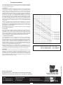
Training instructions
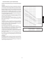
You must consider the following factors in determining the amount of trai-
ning effort required in order to attain tangible physical and health benefits:
1. Intensity:
The level of physical exertion in training must exceed the level of normal
exertion without reaching the point of breathlessness and / or exhaustion.
A suitable guideline for effective training can be taken from the pulse rate.
During training this should rise to the region of between 70% to 85% of
the maximum pulse rate (see the table and formular for determination and
calculation of this).
During the first weeks, the pulse rate should remain at the lower end of
this region, at around 70% of the maximum pulse rate. In the course of
the following weeks and months, the pulse rate should be slowly raised to
the upper limit of 85% of the maximum pulse rate. The better the physical
condition of the person doing the exercise, the more the level of training
should be encreased to remain in the region of between 70% to 85% of the
maximum pulse rate. This should be done by lengthening the time for the
training and / or encreasing the level of difficulty.
If the pulse rate is not shown on the computer display or if for safety reasons
you wish to check your pulse rate, which could have been displayed wrongly
due to error in use, etc., you can do the following:
a. Pulse rate measurement in the conventional way (feeling the pulse at
the wrist, for example, and counting the number of beats in one minute).
b. Pulse rate measurement with a suitable specialised device (available from
dealers specialising in health-related equipment).
2.Frequency
Most experts recommend a combination of health-conscious nutrition, which
must be determined on the basis of your training goal, and physical training
three times a week. A normal adult must train twice a week to maintain his
current level of condition. At least three training sessions a week are required
to improve one’s condition and reduce one’s weight. Of course the ideal
frequency of training is five sessions a week.
3. Planning the training
Each training session should consist of three phases: the warm-up phase,
the training phase, and the cool-down phase. The body temperature and
oxygen intake should be raised slowly in the warm-up phase. This can be
done with gymnastic exercises lasting five to ten minutes.
Then the actual training (training phase) should begin. The training exertion
should be relatively low for the first few minutes and then raised over a
period of 15 to 30 minutes such that the pulse rate reaches the region of
between 70% to 85% of the maximum pulse rate.
In order to support the circulation after the training phase and to prevent
aching or strained muscles later, it is necessary to follow the training phase
with a cool-down phase. This should be consist of stretching exercises and
/ or light gymnastic exercises for a period of five to ten minutes.
4. Motivation
The key to a successful program is regular training. You should set a fixed
time and place for each day of training and prepare yourself mentally for
the training. Only train when you are in the mood for it and always have
your goal in view. With continuous training you will be able to see how you
are progressing day by day and are approaching your personal training
goal bit by bit.
Calculation formula: Maximum pulse rate = 220 - age
(220 minus your age)
90% of the maximum pulse rate = (220 - age) x 0.9
85% of the maximum pulse rate = (220 - age) x 0.85
70% of the maximum pulse rate = (220 - age) x 0.7
Page is loading ...
Page is loading ...
Page is loading ...
Page is loading ...
Page is loading ...
Page is loading ...
Page is loading ...
Page is loading ...
Page is loading ...
Page is loading ...
Page is loading ...
Page is loading ...
Page is loading ...
Page is loading ...
Page is loading ...
Page is loading ...
Page is loading ...
Page is loading ...
Page is loading ...
Page is loading ...
Page is loading ...
Page is loading ...
-
 1
1
-
 2
2
-
 3
3
-
 4
4
-
 5
5
-
 6
6
-
 7
7
-
 8
8
-
 9
9
-
 10
10
-
 11
11
-
 12
12
-
 13
13
-
 14
14
-
 15
15
-
 16
16
-
 17
17
-
 18
18
-
 19
19
-
 20
20
-
 21
21
-
 22
22
-
 23
23
-
 24
24
-
 25
25
-
 26
26
-
 27
27
-
 28
28
-
 29
29
-
 30
30
-
 31
31
-
 32
32
-
 33
33
-
 34
34
-
 35
35
-
 36
36
-
 37
37
-
 38
38
-
 39
39
-
 40
40
-
 41
41
-
 42
42
-
 43
43
-
 44
44


Christopeit EM 3 Owner's manual
- Category
- Spin bikes
- Type
- Owner's manual
- This manual is also suitable for
Ask a question and I''ll find the answer in the document
Finding information in a document is now easier with AI
in other languages
- français: Christopeit EM 3 Le manuel du propriétaire
- Deutsch: Christopeit EM 3 Bedienungsanleitung
- Nederlands: Christopeit EM 3 de handleiding

Other documents
-
Proteus IMT-7500 User manual
-
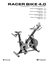 Christopeit Sport Racer Bike 4.0 User manual
-
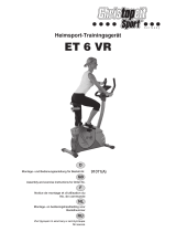 Christopeit Sport ET 6 VR Assembly And Exercise Instructions
-
Skandika SF-2480 Operating instructions
-
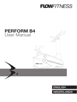 Flow Fitness PERFORM B4 User manual
-
 ultega ERGOMETER RACER 600 User manual
-
Kettler 7851-590.A User manual
-
Spirit XE 295 User manual
-
Hammer ELLYPTECH CT 5 Owner's manual
-
 Flow Fitness Up Town HT4000G User manual


