Page is loading ...

MCM User’s Manual
Artesis A.S. April 2004
For firmware versions 3.2.1 and greater
Document no: MCM 0018-OP-UM-EG-0003

WARNING
Lethal voltages and currents are present at the input terminals of this device. Accordingly, this
MCM unit should be installed and maintained only by qualified, competent personnel who have the
necessary training and experience appropriate to high voltage and current devices. MCM must be
used in accordance with all local and national codes for the installation and operation of electrical
equipment.
Recommended safety precautions should be followed at all times. Both current and voltage
transformers can present lethal currents and voltages when their primaries are energized and
standard practices (i.e. shorting the secondaries of current transformers and removing voltage
transformer fuses) must be respected during installation or any subsequent service.
The unit is designed for operation in a control cabinet with restricted access to the rear terminals
and should not be used in any environment where this is not the case.
MCM should not be used for the purpose of primary protection of electrical equipment.
DISCLAIMER
All rights reserved. No part of this publication may be reproduced, stored in a retrieval system, or
transmitted in any form or by any means, mechanical, photocopying, recording or otherwise,
without prior written permission of Artesis AS. No patent liability is assumed with respect to the
information contained herein.
Whilst every effort has been made to ensure that the information presented in this document is
accurate and up to date, Artesis AS reserves the right to make changes without notice. Neither
Artesis AS nor its designated agents can be held responsible for any errors or omissions, or
problems arising from the application of information contained herein.
Neither Artesis AS nor its affiliates shall be liable to the purchaser of this product or third parties for
damages, losses, costs, or expenses incurred by purchaser or third parties as a result of: accident,
misuse or abuse of this product or unauthorized modifications, repairs, or alterations to this
product, or failure to comply strictly Artesis AS’s operating and maintenance instructions.
Artesis AS shall not be liable against damages or problems arising the use of any options or any
consumable products other than those designated as Artesis original products or Artesis approved
products by Artesis AS.
Product names other than those owned by Artesis AS are used for identification purposes only and
may be trademarks of their respective owners. Artesis AS disclaims any and all rights in those
marks.
Copyright © Artesis 2004 by Artesis AS, 34950 Tuzla, Istanbul.
Artesis AS MCM User’s Manual
MCM 0018-OP-UM-EG-0003
i

Contents
1. Welcome to MCM
1.1 Introduction 1
1.2 Use of this manual 2
2. A quick guide to using MCM
3
3. MCM Installation
3.1 Preliminary checks 4
3.2 MCM unit Installation 4
3.3 Current and Voltage Sensor Installation 5
3.3.1 Low voltage line driven systems 5
3.3.2 Low voltage inverter driven systems 6
3.3.3 Medium/High voltage systems 7
3.4 Rear panel connections 8
3.5 Applying power to the MCM unit 9
3.6 Installing with soft-starter systems 10
3.7 Installing with inverter drives 10
4. MCM Use
4.1 Introduction 11
4.2 The front panel 11
4.3 Configuring for use 13
4.3.1 Entering the password 13
4.3.2 The Edit Settings menu 13
4.3.2.1 First time use 14
4.3.2.2 Calibration factors 15
4.3.2.3 Motor settings 15
4.3.2.4 Communications settings 15
4.4 Running MCM 16
4.4.1 Introduction 16
4.4.2 Alarm messages and status indication 16
4.4.3 Running CHECK MOTOR 18
4.4.4 Setting and checking the input connections 19
4.4.5 Running LEARN and IMPROVE 20
4.4.6 Running RESUME and UPDATE 23
4.4.7 Advanced use 23
4.4.8 Theory of operation 25
4.4.9 Interpreting MCM fault indications 27
4.4.8.1 MCM status values 27
4.4.8.2 Changes in line voltages 30
4.4.8.3 Load changes 31
4.4.10 Error messages 31
4.4.11 Using the relay output 32
4.4.12 Connecting to the serial port 33
Artesis AS MCM User’s Manual
MCM 0018-OP-UM-EG-0003
ii

5 Troubleshooting
5.1 Introduction 37
5.2 Use of the MCM Config utility 37
5.3 Fault diagnosis 40
5.4 Servicing 41
Appendices
1. MCM Error, alarm and warning conditions 42
2. Current and voltage sensor selection 44
3. Connection Diagrams 47
4. Menu settings and parameters 52
5. Edit Settings Menu items 53
6. Flowcharts for MCM use 56
7. Continuous device ratings 62
Artesis AS MCM User’s Manual
MCM 0018-OP-UM-EG-0003
iii

MCM User’s Manual
1. Welcome to MCM
1.1 Introduction
MCM is a revolutionary tool in the battle to keep electric motors
and machinery running at peak performance, whilst maintaining
high plant productivity levels. Used correctly, this unique
instrument is capable of monitoring three phase AC motors of all
sizes and power levels to provide clear, unambiguous indications
when the performance of a particular motor (or even the machinery
it is connected to) begins to degrade. The numerous transducers
employed by other, less advanced instruments have been
replaced by three current sensors and three voltage sensors,
familiar to all those involved with the measurement of electrical
quantities, making the system straightforward to install and use
without in-depth training of personnel.
In addition to its unique capabilities as an intelligent condition-
monitoring device, MCM can also perform many of the functions
of, and indeed replace, the more traditional energy monitoring and
data-logging instruments.
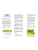
For applications involving the monitoring of many motors and
associated machinery, the networking options available with MCM
allow units to be connected together to a host terminal where they
can all be viewed together. Furthermore, the monitoring software
package allows examination of the various parameters MCM uses
to determine the status of a motor and to trend the parameters as
a visual indication of degradation over time.
Despite its simplicity and ease of use, like any intelligent
electronic, software-based device, it is important that MCM is
installed and used correctly. We recommend strongly that you take
the time to study the information contained within the
accompanying manuals and to familiarize yourself with the
operating principles and practices.
Please contact either your supplier or Artesis AS Customer
Service if you experience any problems in the installation or use of
MCM.
Customer service
Artesis AS MCM User’s Manual
MCM 0018-OP-UM-EG-0003
1

1.2 Use of this manual
This manual explains the basic concepts needed to install and use
MCM. The appendix at the end of the manual provides information
that may be useful to the general user. For further, specific details
please contact Artesis AS.
Artesis AS MCM User’s Manual
MCM 0018-OP-UM-EG-0003
2

2. A quick guide to using MCM
Use of MCM is both simple and straightforward and a summary of
the steps needed for first time use is presented in the following
section. The user is referred to Sections 3 and 4 for a detailed
description and to Appendix 6 for flow charts of MCM usage.
a. Connect the motor and power cables and apply power to the
unit. If the message Bad Flash Data appears, press CLEAR.
b. Select Edit Settings, press ENTER and enter the password
using the UP and DOWN buttons. The default password is the
letter ‘m’.
c. Enter the calibration factors for each channel from the Edit
Settings/Calibration menu.
d. Enter the nominal motor values from the menu Edit
Settings/Motor Settings. Values for RMS voltages and
currents, line frequency, motor speed and connection type are
required.
e. Start the motor
f. Return to the IDLE state and run CHECK MOTOR. Any alarms
issued by MCM should be rectified before proceeding further.
g. Press CLEAR to return to the IDLE state and start MCM by
selecting RUN. If the message Lose learn Data? Clear to exit
appears, press ENTER.
Artesis AS MCM User’s Manual
MCM 0018-OP-UM-EG-0003
3

3. MCM Installation
3.1 Preliminary checks
Please inspect the contents of the MCM package and ensure that
they agree with the information in the Packing list. In the event of
any missing or damaged items, please contact your supplier
immediately. Check also that the power range of the MCM unit is
suitable for the motor to be monitored. The device type can be
found on the MCM label. Artesis A.S. will not accept responsibility
for damage caused to or by any MCM unit that has been
incorrectly installed or installed on a motor system outside the
indicated power range.
3.2 MCM unit Installation
MCM has been designed to mount directly onto the front panel of
the motor switchgear cabinet. Any other usage is not
recommended due to the lethal voltages present at the
terminals. To mount, insert the MCM unit into the prepared
91x91 mm cutout on the cabinet panel and push until the front of
the unit is flush with the panel. Insert the side retainers and
tighten the thumbscrews on each retainer until the MCM unit is
held securely in place.
In common with any device connected to high power
electrical supplies, only suitably qualified personnel should
install and maintain MCM.
Artesis AS MCM User’s Manual
MCM 0018-OP-UM-EG-0003
4

1
2
3
Mounting MCM on a panel
3.3 Current and Voltage Sensor Installation
Dangerous and lethal voltages can develop across the
secondary terminals of open circuit current and voltage
transformers. Before disconnecting any MCM unit to or from a
current transformer, the secondary terminals of the
transformer should be shorted using a link capable of
carrying at several times the nominal output current (i.e. at
least 10A). Before performing any work on a voltage
transformer, its fuse must be removed or switch opened.
Contact breakers or fuses at their sources must protect all
voltage inputs.
3.3.1 Low voltage line driven systems
Three standard 5A secondary, current transformers of appropriate
ratings are recommended for current sensing (please refer to the
appendix at the end of this manual for full specifications). The
secondary terminals of each transformer should be connected to
Artesis AS MCM User’s Manual
MCM 0018-OP-UM-EG-0003
5

the corresponding current measurement terminal pairs, I
11
-I
12,
I
21
-
I
22,
I
31
-I
32
, on the rear of the MCM unit.
Voltage line connections V
R
, V
S
, V
T
should be made directly to
their respective voltage measurement terminals V
1
, V
2
, V
3
at the
rear of the unit.
Please refer to the connection diagrams in the appendix at the
end of this manual for further details.
3.3.2 Low voltage inverter driven systems
The current sensors employed by MCM for inverter driven
systems are Hall-effect type requiring an external DC power
supply. The motor current rating should be checked carefully to
ensure compatibility with the sensors provided. Please refer to the
appendix at the end of this manual for further details on sensor
selection.
High current sensors (for currents greater than 200 A) need to be
mounted separately at a convenient location within the switchgear
cabinet together with their external power supplies. Smaller
sensors are mounted on the same circuit board as the power
supply and should be placed together at the chosen location. In
both cases, the cable carrying power to a single phase of the
motor must be passed through the central hole in the appropriate
current sensor and secured.
The power supply ground should be connected directly to the I
12
,
I
22
,I
32
pairs of current measurement terminals on the rear of the
MCM unit.
Voltage connections V
R
, V
S
, V
T
should be made directly to their
respective voltage measurement terminals V
1
V
2
V
3
at the rear of
the unit.
Note that MCM is not recommended for use with inverters
operating at a chopping frequency lower than 5kHz.
Please refer to the connection diagrams in the appendix at the
end of this manual for further details.
Artesis AS MCM User’s Manual
MCM 0018-OP-UM-EG-0003
6

3.3.3 Medium/High voltage systems
Three standard 5A secondary, current transformers of appropriate
ratings are recommended for current sensing (please refer to the
appendix at the end of this manual for full transformer
specifications). The secondary outputs from each transformer
should be connected to the corresponding current measurement
terminal pairs, I
11
-I
12,
I
21
-I
22,
I
31
-I
32
, on the rear of the MCM unit.
If compensation capacitors are employed, it is essential that
the current transformers be placed between the motor and
the capacitor bank so that only the true motor currents are
measured.
Using compensation
capacitors
Standard 100V secondary voltage transformers should be used to
drop the voltage to usable levels. Connections from the
secondary outputs of the transformers should be made to the
respective voltage measurement terminals V
1
, V
2
V
3
at the rear of
the unit.
Please refer to the connection diagrams in the appendix at the
end of this manual for further details.
Artesis AS MCM User’s Manual
MCM 0018-OP-UM-EG-0003
7

3.4 Rear panel connections
REMOVE ALL POWER PRIOR
TO CHANGING CONNECTIONS
Connections to the MCM rear panel are given in the following
figure. Lethal voltages can be present at the voltage and current
terminals and it is vitally important that power is removed from
both the motor and the MCM unit prior to any connections being
changed.
0
COM. STATUS
RESET
V
3
V
1
V
2
I
32
I
11
I
12
I
21
I
22
I
31
VOLTAGE MEASUREMENT
COM. PORT
N
L
POWER
RX
-
RX
+
TX
-
TX
+
CURRENT MEASUREMENT
RELAY
COM
NC NO
Motor current inputs
Mounting screws
Communication indicator
Hardware reset button
RS 422/485 communications port
Line power Ground Motor voltage inputsRelay port
Artesis AS MCM User’s Manual
MCM 0018-OP-UM-EG-0003
8

The three motor power voltages should be connected to the
corresponding measurement terminals on the MCM rear panel (R
phase to V
1,
S phase to V
2
, and T phase to V
3
) using the
connectors provided. Similarly, the I
R
, I
S
, I
T
connections from the
current sensors should be made to the appropriate current
terminal pairs, I
11
-I
12,
I
21
-I
22,
I
31
-I
32,
on the upper part of the rear
panel.
It is not essential that the all
three sets of phases have the
correct phase relationship as the
phase ordering is determined by
MCM
The order of these voltage and current pairs is not important as
MCM determines the correct ordering when CHECK MOTOR is
first run on the device
Protection against pickup of
Electro-magnetic interference on
the power lines
In order for the unit to function within the harsh electrical
environments often found in switchgear enclosures and to
conform fully with emission standards, it is strongly recommended
that all attached cables be passed twice through the ferrite rings
delivered with the product to their MCM sockets.
A circuit breaker should be provided on the power line in
close proximity to the MCM unit. The circuit breaker should
be clearly marked as the power switch for the device.
A GOOD GROUND IS
ESSENTIAL
Please note that in order to function at its full capability,
MCM requires that the case be connected using a low
impedance cable (12 – 14 AWG cable is recommended)
directly to a high quality ground via the ground terminal on
the power connector. If a suitable ground is not provided,
fault free operation within specifications cannot be
guaranteed.
3.5 Applying power to the MCM unit
Once the motor connections have been made to the rear panel,
power should be applied to the unit. MCM requires between 85
and 240VAC obtained from a single phase, neutral and ground.
At this stage, the Power indicator at the left of the front panel will
light. If this does not occur, please check that the correct voltages
have been applied.
Artesis AS MCM User’s Manual
MCM 0018-OP-UM-EG-0003
9

Immediately on application of power, the LED condition indicators
should briefly flash and activity should be seen on the main
display. The string Initialising followed by a series of
dots will appear. After a few seconds, the display should indicate
that it is in the IDLE mode. MCM is now ready for use. When
using a device for the first time the message
Initialising....
Bad Flash Data
Bad flash data! Press Clear
may be displayed. In this case press the CLEAR button several
times until the message disappears. Once a valid learn mode has
been completed, this message should not occur again.
3.6 Installing with soft-starter systems
MCM can be installed with standard soft-starter systems provided
that they are automatically bypassed immediately after motor
start-up and during subsequent use. Un-bypassed, soft-starter
systems can introduce considerable distortion into the current
waveforms and thus prevent MCM from modeling the properties
of the motor itself. If MCM is to be used with such a system, it is
essential that the maximum current limit of the starter be above
the nominal running motor current so that it is bypassed
effectively during all normal operation. MCM should never be
used on a system that employs soft-starters for speed
control or other un-bypassed uses. Please refer to the
diagrams in the appendix for details of the connections needed for
soft starter systems.
Soft-starters should
always be bypassed
3.7 Installing with inverter drives
Using MCM with inverter driven motors requires the same voltage
connections specified for line driven systems. External Hall-effect
current sensors must be used with inverter systems, as normal
current transformers have insufficient bandwidth for use with the
range of frequencies obtainable from inverters. Please refer to the
diagram in the appendix for details of the connections needed for
inverter driven systems.
Artesis AS MCM User’s Manual
MCM 0018-OP-UM-EG-0003
10

4. MCM Use
4.1 Introduction
Use of MCM is both simple and straightforward once the basic
concepts and principles are understood. This section of the
manual is designed to introduce these concepts and to
demonstrate how MCM is set up, how to check all the
connections and settings, how MCM learns the characteristics of
the system it will monitor and finally how to actually monitor the
motor system. It is recommended that first time users read this
section carefully, as successful operation requires that MCM is
set up and used correctly.
Flowcharts for the main operations are provided in the appendix
at the end of this manual to help users navigate their way through
the various steps involved with setting and running MCM for the
first time.
4.2 The front panel
POWER
Artesıs
motor condition monitor
mcm
ENTER
CLEAR
LCD Display
ENTER button
CLEAR button
Arrow buttons
OK indicator
Line warning indicator
Load warning indicator Examine 1 indicator
Examine 2
indicator
Power Indicator
Artesis AS MCM User’s Manual
MCM 0018-OP-UM-EG-0003
11

Once the sensors have been connected and power has been
applied to the MCM unit, the Power indicator light and the Liquid
Crystal Display (LCD) on the front panel should both be lit. The
LCD should display the message IDLE on the top line, indicating
that the unit is idle and waiting input from the user. When being
used for the first time, the message
Bad flash data! Press Clear
may be displayed. The user should repeatedly press the CLEAR
button until the message disappears. Once data has been written
to flash this message should not occur again.
Using the front panel buttons
Commands are input by pressing one of the six selection buttons
on the front of the unit, UP, DOWN, LEFT, RIGHT, ENTER and
CLEAR. For instance, the user can cycle through the various
modes (IDLE to CHECK MOTOR to RUN to RESUME … and
finally back to IDLE), by repeatedly pressing the UP button. A
particular mode can be selected by pressing ENTER when the
desired mode is displayed on the LCD. The menus are set up on
a hierarchical basis, with each level representing commands of
the same precedence which the user can cycle through by
pressing the UP or DOWN buttons. Pressing CLEAR has the
effect of stopping a particular action and rising up a level in the
hierarchy. Only Edit Settings has nested hierarchy levels more
than two deep. In general whenever ENTER or CLEAR is
pressed, it will be necessary to confirm the action with a second
press of the button; pressing the other button (i.e. CLEAR after
ENTER and vice versa) will cancel the action.
Confirming ENTER and
CLEAR
Similarly, numeric values can be entered using the arrow buttons.
When a value is to be changed, use the LEFT or RIGHT buttons
to move the LCD flashing cursor to the first digit to be edited and
repeatedly press either the UP or DOWN buttons to scroll through
the available alphanumeric characters until the desired one is
displayed. Subsequent digits can be edited by moving to the next
digit using the LEFT or RIGHT buttons and again scrolling with
the UP and DOWN buttons.
Setting numeric values
A schematic diagram showing the menu hierarchy is shown in the
appendix at the end of this manual.
Artesis AS MCM User’s Manual
MCM 0018-OP-UM-EG-0003
12

4.3 Configuring for use
Master reset
When first installed, the MCM unit will be configured for the
default, factory settings which will need to be changed prior to
use. At later times, the factory settings can be restored by
pressing and holding down the LEFT button for about 4 seconds
during power up of the device, until the string:
Press ENTER for general reset
appears. At this stage pressing ENTER will initiate the reset.
Pressing any other button will cause the reset to be ignored and
the device will continue.
4.3.1 Entering the password
To configure the unit, select the Edit Settings mode and press and
confirm ENTER. In order to proceed further, it will be necessary to
enter a password. The factory setting for this password is the
string “m“ and can be entered using the UP and DOWN buttons
to cycle through the alphanumeric characters (‘a’ through ‘z’, ‘0’
through ‘9’). The LEFT and RIGHT buttons are used to shift the
active character in the string. To input the password “m”,
repeatedly press the UP button until the letter ‘m’ appears in the
first position. Press and confirm ENTER and then press ENTER
again to enter the Edit Settings menu.
Default password is ‘m’
It is recommended that at a later time the password be changed,
in order to prevent unauthorized access to the device.
4.3.2 The Edit Settings menu
At this level the following Edit Settings menu items are accessible:
Motor values
Harmonic values
Comm. settings
Motor settings
Calibration
Alarm thresholds
Versions
Run settings
Phase Ordering
Change password
Artesis AS MCM User’s Manual
MCM 0018-OP-UM-EG-0003
13

Please refer to the appendix for a table of these menus and their
sub-menu items. To edit a particular item, first select the item to
edit and press and confirm ENTER. As before use the UP and
DOWN buttons to scroll vertically through individual digits and the
LEFT and RIGHT buttons to change the digit being edited. Some
variables can only take discrete values represented by character
strings and in this case vertical scrolling will shift through the
allowed values. For example, the Parity value under the
Communications settings menu can only have the values EVEN
or ODD and scrolling will repeatedly cycle through these values.
Editing and displaying
menu items
Throughout this manual, paths to menu items are represented by
the word MENU: followed by the list of sub-menus required to
reach the item separated by a forward slash. For example the
path of the Parity value given in the preceding paragraph would
be given as:
Menu paths
MENU: Edit Settings / Password / Comm. Settings / Parity
The forward slash can be thought to represent the action of
pressing and confirming ENTER.
Please note that when the local lockout setting reached by
Local Lockout and passwords
MENU: Edit Settings / Password / Run Settings / Local Lockout
is set, access to the following modes is password protected:
(i) CHECK MOTOR
(ii) RUN
(iii) RESUME
(iv) UPDATE
In addition, canceling any of these modes by pressing CLEAR
also requires the user to supply a password. All passwords are
the same as that used to access Edit Settings.
4.3.2.1 First time use
Before MCM can be used for the first time it is necessary to
change various settings from their default values (a table outlining
the MCM settings is shown in the appendix). Values relevant to
the connected motor must be set for the quantities described in
the following sections.
Artesis AS MCM User’s Manual
MCM 0018-OP-UM-EG-0003
14

4.3.2.2 Calibration factors
Hall-effect current sensors and assemblies supplied with MCM
should be accompanied by a calibration document containing the
sensor’s calibration factor. The values of each calibration factor
should be entered into the correct setting under the Calibration
menu. It is important that the correct factor be entered for each
channel, as MCM will not function correctly if the calibration
factors are incorrect.
For channels connected to transformer sensors, the calibration
factor should be equal to the nominal ratio of the primary to
secondary turns. For example a 100A current transformer with a
5A output and a single primary turn would require a calibration
factor of 20. The same transformer with two primary turns would
require a calibration factor of 10. A 6500V voltage transformer
with a nominal secondary voltage of 100V would require a
calibration factor of 65.
Any channel connected directly to the motor without an external
sensor (i.e. voltage connections on low voltage units) requires a
calibration factor of 1.
4.3.2.3 Motor settings
Nominal voltage, current and
frequency
The nominal voltage, current and speed (in rpm) of the attached
motor must be entered under the Motor Settings menu. These
values can be obtained from the motor specifications. MCM uses
these values to determine whether the motor complies with its
specifications and incorrect values are likely to raise alarms. The
nominal line frequency (or most commonly expected frequency in
the case of an inverter) should also be set. Similarly, the motor
connection type must be set to one of
Setting the motor connection
type
Star
Delta
The value of this setting should be found from the motor
installation documentation.
Finally, if the MCM networking option is being used, it is
recommended that the motor serial number (or any other short
identifier string) be entered as a means of identifying the motor to
the software. This is not obligatory, and both the networking
software and MCM can function without this information.
Artesis AS MCM User’s Manual
MCM 0018-OP-UM-EG-0003
15

4.3.2.4 Communications settings
Setting the device address
If the MCM networking options are to be used, the MCM network
address must be supplied. By default this is set to 0, which by
convention is the address of the host terminal. Use of this address
will therefore disrupt communications over the network and must
be changed prior to connection. Any address between 1 and 255
can be selected although it is important to check that the selected
address is not in use by any other device on the same node.
Please refer to the MCMViewPro networking documentation for
full details of address selection.
All other communications settings should be left at the factory
defaults if the MCMViewPro networking software is being used. If
another software package is employed (i.e. SCADA software),
please refer to its documentation for communication settings.
Other communications settings
MCM can use both 2 and 4 wire (RS 422 and RS485 standards
respectively) communications at up to 19200 Baud. Please refer
to section 4.4.12 for further information.
4.4 Running MCM
4.4.1 Introduction
Having configured MCM for a particular motor, it can now be used
for its intended purpose of monitoring and assessing the condition
of the motor. In general, this involves first running MCM to
measure and learn the properties of the motor and then running
MCM in its test mode to perform the actual monitoring. Without
the learning period MCM has insufficient information on which to
base its decisions as the motor ages and will not perform to its
specifications. For this reason, MCM ensures that a valid learning
period is first performed before allowing the user to request the
device to monitor the motor.
4.4.2 Alarm messages and status indication
Alarms are specific to the
motor
MCM divides warning messages into the categories of warnings,
alarms and errors. Warnings inform the user that non-critical
conditions have arisen that the user should be aware of but do not
affect the performance of MCM. Alarms provide information
specific to the motor being tested and are indications of faults
caused by incorrect connections to the motor, the supplied line
Artesis AS MCM User’s Manual
MCM 0018-OP-UM-EG-0003
16
/