
E1 AND E2 USER’S GUIDE
Form 1563-220304—March 2022
43044 Business Park Drive • Temecula • CA 92590-3614
Phone: 800-321-OPTO (6786) or 951-695-3000
Fax: 800-832-OPTO (6786) or 951-695-2712
www.opto22.com
Product Support Services
800-TEK-OPTO (835-6786) or 951-695-3080
Fax: 951-695-3017
Email: [email protected]
Web: support.opto22.com

E1 and E2 User’s Guide
ii
E1 and E2 User’s Guide
Form 1563-220304—March 2022
Copyright © 2005-2022 Opto 22.
All rights reserved.
Printed in the United States of America.
The information in this manual has been checked carefully and is believed to be accurate; however, Opto 22 assumes no
responsibility for possible inaccuracies or omissions. Specifications are subject to change without notice.
Opto 22 warrants all of its products to be free from defects in material or workmanship for 30 months from the
manufacturing date code. This warranty is limited to the original cost of the unit only and does not cover installation, labor,
or any other contingent costs. Opto 22 I/O modules and solid-state relays with date codes of 1/96 or newer are guaranteed
for life. This lifetime warranty excludes reed relay modules, groov and SNAP serial communication modules, SNAP PID
modules, and modules that contain mechanical contacts or switches. Opto 22 does not warrant any product, components,
or parts not manufactured by Opto 22; for these items, the warranty from the original manufacturer applies. Refer to Opto
22 form 1042 for complete warranty information.
Wired+Wireless controllers and brains are licensed under one or more of the following patents: U.S. Patent No(s). 5282222,
RE37802, 6963617; Canadian Patent No. 2064975; European Patent No. 1142245; French Patent No. 1142245; British Patent
No. 1142245; Japanese Patent No. 2002535925A; German Patent No. 60011224.
Opto 22 FactoryFloor, groov, groov EPIC, groov RIO, mobile made simple, The Edge of Automation, Optomux, and Pamux
are registered trademarks of Opto 22. Generation 4, groov Server, ioControl, ioDisplay, ioManager, ioProject, ioUtilities,
mistic, Nvio, Nvio.net Web Portal, OptoConnect, OptoControl, OptoDataLink, OptoDisplay, OptoEMU, OptoEMU Sensor,
OptoEMU Server, OptoOPCServer, OptoScript, OptoServer, OptoTerminal, OptoUtilities, PAC Control, PAC Display, PAC
Manager, PAC Project, PAC Project Basic, PAC Project Professional, SNAP Ethernet I/O, SNAP I/O, SNAP OEM I/O, SNAP PAC
System, SNAP Simple I/O, SNAP Ultimate I/O, and Wired+Wireless are trademarks of Opto 22.
ActiveX, JScript, Microsoft, MS-DOS, VBScript, Visual Basic, Visual C++, Windows, and Windows Vista are either registered
trademarks or trademarks of Microsoft Corporation in the United States and other countries. Linux is a registered
trademark of Linus Torvalds. ARCNET is a registered trademark of Datapoint Corporation. Modbus is a registered trademark
of Schneider Electric, licensed to the Modbus Organization, Inc. Wiegand is a registered trademark of Sensor Engineering
Corporation. Allen-Bradley, CompactLogix, ControlLogix, MicroLogix, SLC, and RSLogix are either registered trademarks or
trademarks of Rockwell Automation. CIP and EtherNet/IP are trademarks of ODVA. Raspberry Pi is a trademark of the
Raspberry Pi Foundation. The registered trademark Ignition by Inductive Automation® is owned by Inductive Automation
and is registered in the United States and may be pending or registered in other countries. CODESYS® is a registered
trademark of 3S-Smart Software Solutions GmbH.
groov includes software developed by the OpenSSL Project for use in the OpenSSL Toolkit. (http://www.openssl.org)
All other brand or product names are trademarks or registered trademarks of their respective companies or organizations.
Opto 22
Your Edge in Automation.

E1 and E2 User’s Guide iii
iii
Table of Contents
Chapter 1: Introduction . . . . . . . . . . . . . . . . . . . . . . . . . . . . . . . . . . . . . . . . . . . . . . . . . . . . . . . . .1
E1 Brain Board . . . . . . . . . . . . . . . . . . . . . . . . . . . . . . . . . . . . . . . . . . . . . . . . . . . . . . . . . . . . . . . . . . . . . . . . . . . . . . . . .1
E2 Brain Board . . . . . . . . . . . . . . . . . . . . . . . . . . . . . . . . . . . . . . . . . . . . . . . . . . . . . . . . . . . . . . . . . . . . . . . . . . . . . . . . .2
About this Guide. . . . . . . . . . . . . . . . . . . . . . . . . . . . . . . . . . . . . . . . . . . . . . . . . . . . . . . . . . . . . . . . . . . . . . . . . . . . . . . . . . . 2
Other Documents You May Need . . . . . . . . . . . . . . . . . . . . . . . . . . . . . . . . . . . . . . . . . . . . . . . . . . . . . . . . . . . . . . .3
For Help . . . . . . . . . . . . . . . . . . . . . . . . . . . . . . . . . . . . . . . . . . . . . . . . . . . . . . . . . . . . . . . . . . . . . . . . . . . . . . . . . . . . . . . . . . . 4
E1 and E2 Features and Specifications. . . . . . . . . . . . . . . . . . . . . . . . . . . . . . . . . . . . . . . . . . . . . . . . . . . . . . . . . . . . . . . 5
E1 Brain Board Features . . . . . . . . . . . . . . . . . . . . . . . . . . . . . . . . . . . . . . . . . . . . . . . . . . . . . . . . . . . . . . . . . . . . . . . .5
E2 Brain Board Features . . . . . . . . . . . . . . . . . . . . . . . . . . . . . . . . . . . . . . . . . . . . . . . . . . . . . . . . . . . . . . . . . . . . . . . .6
Specifications . . . . . . . . . . . . . . . . . . . . . . . . . . . . . . . . . . . . . . . . . . . . . . . . . . . . . . . . . . . . . . . . . . . . . . . . . . . . . . . . .8
Dimensional Drawings . . . . . . . . . . . . . . . . . . . . . . . . . . . . . . . . . . . . . . . . . . . . . . . . . . . . . . . . . . . . . . . . . . . . . . . . .9
E1 Dimensions . . . . . . . . . . . . . . . . . . . . . . . . . . . . . . . . . . . . . . . . . . . . . . . . . . . . . . . . . . . . . . . . . . . . . . . . . . . .9
E2 Dimensions . . . . . . . . . . . . . . . . . . . . . . . . . . . . . . . . . . . . . . . . . . . . . . . . . . . . . . . . . . . . . . . . . . . . . . . . . . . .9
LED Descriptions . . . . . . . . . . . . . . . . . . . . . . . . . . . . . . . . . . . . . . . . . . . . . . . . . . . . . . . . . . . . . . . . . . . . . . . . . . . . . . . . . . 10
E1 LED Descriptions . . . . . . . . . . . . . . . . . . . . . . . . . . . . . . . . . . . . . . . . . . . . . . . . . . . . . . . . . . . . . . . . . . . . . . . . . . 10
E2 LED Descriptions . . . . . . . . . . . . . . . . . . . . . . . . . . . . . . . . . . . . . . . . . . . . . . . . . . . . . . . . . . . . . . . . . . . . . . . . . 10
LED Blink Codes . . . . . . . . . . . . . . . . . . . . . . . . . . . . . . . . . . . . . . . . . . . . . . . . . . . . . . . . . . . . . . . . . . . . . . . . . . . . . 11
Chapter 2: Installation . . . . . . . . . . . . . . . . . . . . . . . . . . . . . . . . . . . . . . . . . . . . . . . . . . . . . . . . 13
What You Will Need. . . . . . . . . . . . . . . . . . . . . . . . . . . . . . . . . . . . . . . . . . . . . . . . . . . . . . . . . . . . . . . . . . . . . . . . . . . . . . . 13
Installing Software . . . . . . . . . . . . . . . . . . . . . . . . . . . . . . . . . . . . . . . . . . . . . . . . . . . . . . . . . . . . . . . . . . . . . . . . . . . . . . . . 13
Mounting the Brain Board . . . . . . . . . . . . . . . . . . . . . . . . . . . . . . . . . . . . . . . . . . . . . . . . . . . . . . . . . . . . . . . . . . . . . . . . . 13
Connecting the Power Supply . . . . . . . . . . . . . . . . . . . . . . . . . . . . . . . . . . . . . . . . . . . . . . . . . . . . . . . . . . . . . . . . . . . . . 15
Connecting the E1 and E2 to Earth Ground . . . . . . . . . . . . . . . . . . . . . . . . . . . . . . . . . . . . . . . . . . . . . . . . . . . . . . . . . 16
Installing I/O Modules . . . . . . . . . . . . . . . . . . . . . . . . . . . . . . . . . . . . . . . . . . . . . . . . . . . . . . . . . . . . . . . . . . . . . . . . . . . . . 16
Connecting to a Serial Network . . . . . . . . . . . . . . . . . . . . . . . . . . . . . . . . . . . . . . . . . . . . . . . . . . . . . . . . . . . . . . . . . . . . 16
Wiring Serial Communications and Power . . . . . . . . . . . . . . . . . . . . . . . . . . . . . . . . . . . . . . . . . . . . . . . . . . . . 16
Setting Jumpers (Serial Only) . . . . . . . . . . . . . . . . . . . . . . . . . . . . . . . . . . . . . . . . . . . . . . . . . . . . . . . . . . . . . . . . . 17
Connecting to an Ethernet Network. . . . . . . . . . . . . . . . . . . . . . . . . . . . . . . . . . . . . . . . . . . . . . . . . . . . . . . . . . . . . . . . 21
Security . . . . . . . . . . . . . . . . . . . . . . . . . . . . . . . . . . . . . . . . . . . . . . . . . . . . . . . . . . . . . . . . . . . . . . . . . . . . . . . . . . . . . 21
System Components . . . . . . . . . . . . . . . . . . . . . . . . . . . . . . . . . . . . . . . . . . . . . . . . . . . . . . . . . . . . . . . . . . . . . . . . . . . . . . 22
I/O Modules and Mounting Racks . . . . . . . . . . . . . . . . . . . . . . . . . . . . . . . . . . . . . . . . . . . . . . . . . . . . . . . . . . . . 22
Cable . . . . . . . . . . . . . . . . . . . . . . . . . . . . . . . . . . . . . . . . . . . . . . . . . . . . . . . . . . . . . . . . . . . . . . . . . . . . . . . . . . . . . . . 22
Power Supply . . . . . . . . . . . . . . . . . . . . . . . . . . . . . . . . . . . . . . . . . . . . . . . . . . . . . . . . . . . . . . . . . . . . . . . . . . . . . . . 23

E1 and E2 User’s Guide
iv
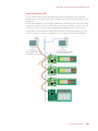
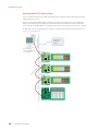
Chapter 3: Architecture and Communication . . . . . . . . . . . . . . . . . . . . . . . . . . . . . . . . . . . .25
Communication Options . . . . . . . . . . . . . . . . . . . . . . . . . . . . . . . . . . . . . . . . . . . . . . . . . . . . . . . . . . . . . . . . . . . . . . . . . . 25
Accessing E1 and E2 Brain Boards Over the internet . . . . . . . . . . . . . . . . . . . . . . . . . . . . . . . . . . . . . . . . . . . 26
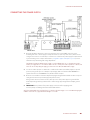
System Architecture . . . . . . . . . . . . . . . . . . . . . . . . . . . . . . . . . . . . . . . . . . . . . . . . . . . . . . . . . . . . . . . . . . . . . . . . . . . . . . 26
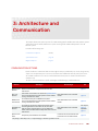
Typical Control System Using Optomux . . . . . . . . . . . . . . . . . . . . . . . . . . . . . . . . . . . . . . . . . . . . . . . . . . . . . . . 27
Optomux Over Ethernet . . . . . . . . . . . . . . . . . . . . . . . . . . . . . . . . . . . . . . . . . . . . . . . . . . . . . . . . . . . . . . . . . 27
Optomux Over Serial . . . . . . . . . . . . . . . . . . . . . . . . . . . . . . . . . . . . . . . . . . . . . . . . . . . . . . . . . . . . . . . . . . . . 27
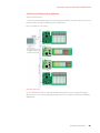
Control System Plus Data Acquisition via OPC . . . . . . . . . . . . . . . . . . . . . . . . . . . . . . . . . . . . . . . . . . . . . . . . . 28
Communicating with Modbus/TCP Clients . . . . . . . . . . . . . . . . . . . . . . . . . . . . . . . . . . . . . . . . . . . . . . . . . . . . 29
PAC Project Control System . . . . . . . . . . . . . . . . . . . . . . . . . . . . . . . . . . . . . . . . . . . . . . . . . . . . . . . . . . . . . . . . . . 29
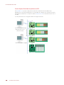
Building Custom Applications with the OptoMMP Protocol . . . . . . . . . . . . . . . . . . . . . . . . . . . . . . . . . . . . 31
Migration Options . . . . . . . . . . . . . . . . . . . . . . . . . . . . . . . . . . . . . . . . . . . . . . . . . . . . . . . . . . . . . . . . . . . . . . . . . . . . . . . . 32
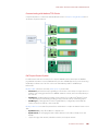
Acquiring Data Using OPC . . . . . . . . . . . . . . . . . . . . . . . . . . . . . . . . . . . . . . . . . . . . . . . . . . . . . . . . . . . . . . . . . . . 33
Adding Modbus/TCP Communication . . . . . . . . . . . . . . . . . . . . . . . . . . . . . . . . . . . . . . . . . . . . . . . . . . . . . . . . 34
Chapter 4: Maintaining the E1 and E2 . . . . . . . . . . . . . . . . . . . . . . . . . . . . . . . . . . . . . . . . . . .35
Assigning or Viewing the IP Address . . . . . . . . . . . . . . . . . . . . . . . . . . . . . . . . . . . . . . . . . . . . . . . . . . . . . . . . . . . . . . . 35
Resetting the Brain Board to Factory Defaults. . . . . . . . . . . . . . . . . . . . . . . . . . . . . . . . . . . . . . . . . . . . . . . . . . . . . . . 35
Loading New Firmware . . . . . . . . . . . . . . . . . . . . . . . . . . . . . . . . . . . . . . . . . . . . . . . . . . . . . . . . . . . . . . . . . . . . . . . . . . . 36
Chapter 5: Using Modbus/TCP . . . . . . . . . . . . . . . . . . . . . . . . . . . . . . . . . . . . . . . . . . . . . . . . . 41
Introduction . . . . . . . . . . . . . . . . . . . . . . . . . . . . . . . . . . . . . . . . . . . . . . . . . . . . . . . . . . . . . . . . . . . . . . . . . . . . . . . . . . . . . . 41
Overview of Modbus/TCP Communication . . . . . . . . . . . . . . . . . . . . . . . . . . . . . . . . . . . . . . . . . . . . . . . . . . . . . . . . . 41
Understanding Opto 22 and Modbus/TCP Differences . . . . . . . . . . . . . . . . . . . . . . . . . . . . . . . . . . . . . . . . . 41
Function Codes Supported . . . . . . . . . . . . . . . . . . . . . . . . . . . . . . . . . . . . . . . . . . . . . . . . . . . . . . . . . . . . . . . . . . . 42
Communication Packet . . . . . . . . . . . . . . . . . . . . . . . . . . . . . . . . . . . . . . . . . . . . . . . . . . . . . . . . . . . . . . . . . . . . . . 42
Exception Errors . . . . . . . . . . . . . . . . . . . . . . . . . . . . . . . . . . . . . . . . . . . . . . . . . . . . . . . . . . . . . . . . . . . . . . . . . . . . . 43
Referencing I/O Points for E1 and E2 Brain Boards . . . . . . . . . . . . . . . . . . . . . . . . . . . . . . . . . . . . . . . . . . . . . . . . . . 44
Configuring I/O Points . . . . . . . . . . . . . . . . . . . . . . . . . . . . . . . . . . . . . . . . . . . . . . . . . . . . . . . . . . . . . . . . . . . . . . . . . . . . 45
Using Digital Point Features . . . . . . . . . . . . . . . . . . . . . . . . . . . . . . . . . . . . . . . . . . . . . . . . . . . . . . . . . . . . . . . . . . 45
Latches . . . . . . . . . . . . . . . . . . . . . . . . . . . . . . . . . . . . . . . . . . . . . . . . . . . . . . . . . . . . . . . . . . . . . . . . . . . . . . . . 45
Counters . . . . . . . . . . . . . . . . . . . . . . . . . . . . . . . . . . . . . . . . . . . . . . . . . . . . . . . . . . . . . . . . . . . . . . . . . . . . . . . 45
Using Analog Point Features . . . . . . . . . . . . . . . . . . . . . . . . . . . . . . . . . . . . . . . . . . . . . . . . . . . . . . . . . . . . . . . . . 46
Scaling . . . . . . . . . . . . . . . . . . . . . . . . . . . . . . . . . . . . . . . . . . . . . . . . . . . . . . . . . . . . . . . . . . . . . . . . . . . . . . . . 46
Maximum and Minimum Values (Peaks and Valleys) . . . . . . . . . . . . . . . . . . . . . . . . . . . . . . . . . . . . . . 46
Offset and Gain . . . . . . . . . . . . . . . . . . . . . . . . . . . . . . . . . . . . . . . . . . . . . . . . . . . . . . . . . . . . . . . . . . . . . . . . . 46
Modbus/TCP Memory Map for E1 and E2 Brain Boards . . . . . . . . . . . . . . . . . . . . . . . . . . . . . . . . . . . . . . . . . . . . . . 46
Coils . . . . . . . . . . . . . . . . . . . . . . . . . . . . . . . . . . . . . . . . . . . . . . . . . . . . . . . . . . . . . . . . . . . . . . . . . . . . . . . . . . . . . . . . 46
Inputs . . . . . . . . . . . . . . . . . . . . . . . . . . . . . . . . . . . . . . . . . . . . . . . . . . . . . . . . . . . . . . . . . . . . . . . . . . . . . . . . . . . . . . . 47
Input Registers . . . . . . . . . . . . . . . . . . . . . . . . . . . . . . . . . . . . . . . . . . . . . . . . . . . . . . . . . . . . . . . . . . . . . . . . . . . . . . 47
Holding Registers . . . . . . . . . . . . . . . . . . . . . . . . . . . . . . . . . . . . . . . . . . . . . . . . . . . . . . . . . . . . . . . . . . . . . . . . . . . . 47
Using Input and Holding Registers . . . . . . . . . . . . . . . . . . . . . . . . . . . . . . . . . . . . . . . . . . . . . . . . . . . . . . . . . . . 48
Chapter 6: Troubleshooting . . . . . . . . . . . . . . . . . . . . . . . . . . . . . . . . . . . . . . . . . . . . . . . . . . .51
Troubleshooting Ethernet Communications. . . . . . . . . . . . . . . . . . . . . . . . . . . . . . . . . . . . . . . . . . . . . . . . . . . . . . . . 51
Pinging the Brain Board . . . . . . . . . . . . . . . . . . . . . . . . . . . . . . . . . . . . . . . . . . . . . . . . . . . . . . . . . . . . . . . . . . . . . . 52
Accessing the Brain Board with PAC Manager . . . . . . . . . . . . . . . . . . . . . . . . . . . . . . . . . . . . . . . . . . . . . . . . . 52

E1 and E2 User’s Guide v
Solving Network Problems . . . . . . . . . . . . . . . . . . . . . . . . . . . . . . . . . . . . . . . . . . . . . . . . . . . . . . . . . . . . . . . . . . . 53
Create a Network Diagram . . . . . . . . . . . . . . . . . . . . . . . . . . . . . . . . . . . . . . . . . . . . . . . . . . . . . . . . . . . . . . 53
Analyze Communication Packets . . . . . . . . . . . . . . . . . . . . . . . . . . . . . . . . . . . . . . . . . . . . . . . . . . . . . . . . 53
Have Your Network Certified . . . . . . . . . . . . . . . . . . . . . . . . . . . . . . . . . . . . . . . . . . . . . . . . . . . . . . . . . . . . 53
Troubleshooting Serial Communications . . . . . . . . . . . . . . . . . . . . . . . . . . . . . . . . . . . . . . . . . . . . . . . . . . . . . . . . . . . 54
Solving Common Communications Errors . . . . . . . . . . . . . . . . . . . . . . . . . . . . . . . . . . . . . . . . . . . . . . . . . . . . . 54
Power Tips . . . . . . . . . . . . . . . . . . . . . . . . . . . . . . . . . . . . . . . . . . . . . . . . . . . . . . . . . . . . . . . . . . . . . . . . . . . . . 54
Jumper Tips . . . . . . . . . . . . . . . . . . . . . . . . . . . . . . . . . . . . . . . . . . . . . . . . . . . . . . . . . . . . . . . . . . . . . . . . . . . . 54
Communication Wiring Tips . . . . . . . . . . . . . . . . . . . . . . . . . . . . . . . . . . . . . . . . . . . . . . . . . . . . . . . . . . . . . 55
Other Tips: . . . . . . . . . . . . . . . . . . . . . . . . . . . . . . . . . . . . . . . . . . . . . . . . . . . . . . . . . . . . . . . . . . . . . . . . . . . . . . 56
Error Codes When Using Opto 22 Optomux Driver . . . . . . . . . . . . . . . . . . . . . . . . . . . . . . . . . . . . . . . . . . . . . 56
Errors Returned by the Brain Board . . . . . . . . . . . . . . . . . . . . . . . . . . . . . . . . . . . . . . . . . . . . . . . . . . . . . . . 56
Driver Errors . . . . . . . . . . . . . . . . . . . . . . . . . . . . . . . . . . . . . . . . . . . . . . . . . . . . . . . . . . . . . . . . . . . . . . . . . . . . 57
Other Error Codes . . . . . . . . . . . . . . . . . . . . . . . . . . . . . . . . . . . . . . . . . . . . . . . . . . . . . . . . . . . . . . . . . . . . . . . . . . . . 57
General Troubleshooting . . . . . . . . . . . . . . . . . . . . . . . . . . . . . . . . . . . . . . . . . . . . . . . . . . . . . . . . . . . . . . . . . . . . . . . . . . 57
Serial Communications Questions and Answers . . . . . . . . . . . . . . . . . . . . . . . . . . . . . . . . . . . . . . . . . . 59
Appendix A: Serial-to-Ethernet Routing . . . . . . . . . . . . . . . . . . . . . . . . . . . . . . . . . . . . . . 61
Creating a Routing Table . . . . . . . . . . . . . . . . . . . . . . . . . . . . . . . . . . . . . . . . . . . . . . . . . . . . . . . . . . . . . . . . . . . . . . . . . . 63
Sample Routing Table . . . . . . . . . . . . . . . . . . . . . . . . . . . . . . . . . . . . . . . . . . . . . . . . . . . . . . . . . . . . . . . . . . . . . . . 64
Enabling Serial-to-Ethernet Routing. . . . . . . . . . . . . . . . . . . . . . . . . . . . . . . . . . . . . . . . . . . . . . . . . . . . . . . . . . . . . . . . 64
Disabling Serial-to-Ethernet Routing . . . . . . . . . . . . . . . . . . . . . . . . . . . . . . . . . . . . . . . . . . . . . . . . . . . . . . . . . . . . . . . 66
Appendix B: Using the OmuxSettings File . . . . . . . . . . . . . . . . . . . . . . . . . . . . . . . . . . . . . 67
About the OmuxSettings File . . . . . . . . . . . . . . . . . . . . . . . . . . . . . . . . . . . . . . . . . . . . . . . . . . . . . . . . . . . . . . . . . . . . . . 67
Changing the OmuxSettings File. . . . . . . . . . . . . . . . . . . . . . . . . . . . . . . . . . . . . . . . . . . . . . . . . . . . . . . . . . . . . . . . . . . 67
Appendix C: Licensing Information . . . . . . . . . . . . . . . . . . . . . . . . . . . . . . . . . . . . . . . . . . . .71
Software Licenses Used in E1 and E2 Brain Boards . . . . . . . . . . . . . . . . . . . . . . . . . . . . . . . . . . . . . . . . . . . . . . . . . . 71
Opto 22 License Agreement for Embedded Software . . . . . . . . . . . . . . . . . . . . . . . . . . . . . . . . . . . . . . . . . . 71
GNU General Public License . . . . . . . . . . . . . . . . . . . . . . . . . . . . . . . . . . . . . . . . . . . . . . . . . . . . . . . . . . . . . . . . . . 71
GNU Lesser General Public License . . . . . . . . . . . . . . . . . . . . . . . . . . . . . . . . . . . . . . . . . . . . . . . . . . . . . . . . . . . 72
Berkeley Software Distribution License . . . . . . . . . . . . . . . . . . . . . . . . . . . . . . . . . . . . . . . . . . . . . . . . . . . . . . . . 72
Opto 22 License Agreement for Embedded Software . . . . . . . . . . . . . . . . . . . . . . . . . . . . . . . . . . . . . . . . . . . . . . . 73
GNU General Public License . . . . . . . . . . . . . . . . . . . . . . . . . . . . . . . . . . . . . . . . . . . . . . . . . . . . . . . . . . . . . . . . . . . . . . . 74
GNU Lesser General Public License. . . . . . . . . . . . . . . . . . . . . . . . . . . . . . . . . . . . . . . . . . . . . . . . . . . . . . . . . . . . . . . . . 78
Index . . . . . . . . . . . . . . . . . . . . . . . . . . . . . . . . . . . . . . . . . . . . . . . . . . . . . . . . . . . . . . . . . . . . . . . 85

E1 and E2 User’s Guide
vi

E1 and E2 User’s Guide 1
1
Chapter 1\
1: Introduction
E1 digital and E2 analog brain boards are intelligent I/O (input/output) processors that communicate with a
host computer and also perform control functions at each point of I/O.
Designed as drop-in replacements for Opto 22’s B1 and B2 brain boards, the E1 and E2 have the same
Optomux and serial network capabilities, but they offer significant new features: Ethernet support, additional
protocol support, and migration and expansion opportunities. For example, you can use PAC Project™
software applications with E1 or E2 I/O systems to control, monitor, and acquire data.
E1 and E2 brain boards can communicate using Optomux over serial and Ethernet, and using Opto 22’s
OptoMMP™ protocol over Ethernet. OLE for Process Control (OPC) and Modbus/TCP clients can readily obtain
data from the system over Ethernet. For detailed information on protocols and system architecture, see
Chapter 3: Architecture and Communication.
E1 Brain Board
The E1 brain board is a digital-only processor
that can be used with a variety of
input/output (I/O) modules and mounting
racks. The E1 supports up to 16 I/O modules.
In addition to On/Off control, the E1 brain
board provides the following digital
functions:
•Read/write to point
•Input latches
•Counters
•Pulse duration measurement
•Pulse generation
•Time delays
•Watchdog timer
For detailed descriptions of E1 features, see
“E1 and E2 Features and Specifications” on
page 5.
E1 Brain Board

ABOUT THIS GUIDE
E1 and E2 User’s Guide
2
E2 Brain Board
The E2 brain board is an analog-only
processor used with G1 (Standard)
analog modules and G1-series mounting
racks.
In addition to simple input and output,
the E2 brain board provides the following
analog functions:
•Read/write to point in Engineering
units
•Read/write to point in counts
•Input averaging
•Minimum/maximum values
(peak/valley recording)
•High/low limit testing
•Offset and gain calculation
•Waveform generation
•Watchdog timer
For detailed descriptions of E2 features, see E1 and E2 Features and Specifications on page 5.
ABOUT THIS GUIDE
This guide shows you how to install and use E1 and E2 brain boards. This guide assumes that you have some
familiarity with TCP/IP, UDP/IP, and Ethernet networking. If you are not familiar with these subjects, we strongly
suggest you consult commercially available resources to learn about them before attempting to install or use
these products.
If you are using Modbus/TCP for communicating with E1 and E2 brain boards, this guide assumes that you are
already familiar with Modbus/TCP.
The following chapters are included in this user’s guide:
Chapter 1: Introduction—Provides a brief description of the E1 and E2 brain boards, the contents of this
guide, a list of other important documents, and how to reach Opto 22 Product Support.
Chapter 2: Installation—Details what you need to install E1 and E2 brain boards, how to mount the brain
board, and how to connect to a serial or Ethernet network.
Chapter 3: Architecture and Communication—Describes how E1 and E2 brain boards fit into your system
architecture and how to communicate with them.
Chapter 4: Maintaining the E1 and E2—Describes assigning and changing IP addresses, resetting the brain
board to factory defaults, and upgrading firmware.
Chapter 5: Using Modbus/TCP—Provides configuration information for those communicating with the E1
and E2 using Modbus/TCP.
Chapter 6: Troubleshooting—Provides tips for resolving difficulties you may encounter while working with
E1 and E2 brain boards.
Appendix A: Serial-to-Ethernet Routing—Presents how to set up the E1 and E2 to route data between
serial and Ethernet networks.
E2 Brain Board

CHAPTER 1: INTRODUCTION
E1 and E2 User’s Guide 3
Appendix B: Using the OmuxSettings File—Describes how to set Optomux network settings using the
OmuxSettings file.
Appendix C: Licensing Information—Presents licensing information for software components.
Other Documents You May Need
See the following additional guides for the information listed. All documents referenced in this document are
available on our website, www.opto22.com..
For this information See this guide Form #
Writing custom applications using the Optomux
protocol over Ethernet or serial. (Combines pre-
vious forms 92 and 203 into new form number.)
Optomux Protocol Guide 1572
Configuring E1s and E2s to use with PAC Proj-
ect software, Modbus/TCP applications, and
custom OptoMMP
For minimum E1/E2 firmware R1.2a, PAC firmware
9.5, and PAC Project 9.5:
•PAC Control User’s Guide, Legacy Edition
•PAC Manager User’s Guide, Legacy Edition
For older firmware or software:
I/O Configuration for E1 and E2 Brain Boards
1710
1714
1576
Writing custom applications using the OptoMMP
protocol over Ethernet OptoMMP Protocol Guide 1465
Providing reliable power to Opto 22 equipment Using Power Supplies with Opto 22 Systems 1271
Programming Opto 22 SNAP PAC controllers PAC Control User’s Guide, Legacy Edition
PAC Control Command Reference. Legacy Edition
1710
1711
B1/B2 system architecture, features, specifica-
tions, installation and wiring, and jumpers
Optomux 16-Channel Digital and Analog Brain
Board Data Sheet (B1/B2) 463
E1/E2 protocol support, comparison of B1/B2
and E1/E2, detailed description E1 and E2 Brain Board Data Sheet 1546

FOR HELP
E1 and E2 User’s Guide
4
FOR HELP
If you have problems installing or using E1 and E2 brain boards and cannot find the help you need in this
guide or on our website, contact Opto 22 Product Support.
Phone: 800-TEK-OPTO (800-835-6786 toll-free
in the U.S. and Canada)
951-695-3080
Monday through Friday,
7 a.m. to 5 p.m. Pacific Time
Email: suppor[email protected]
Opto 22 website: www.opto22.com
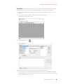
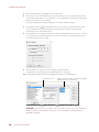
When calling for technical support, you can help us help you faster if you provide the following information to
the Product Support engineer:
•A screen capture of the Help > About dialog box showing software product and version (available by
clicking Help > About in the application’s menu bar).
•Opto 22 hardware part numbers or models that you’re working with.
•Firmware version:
– For SNAP controllers and brains: available in PAC Manager by clicking Tools > Inspect.
–For groov EPIC processors and groov RIO modules: available in groov Manage by clicking Info and
Help > About.
•Specific error messages you received.
•Version of your computer’s operating system.
•For PAC Control, PAC Display, OptoOPCServer, or PAC Manager, you may be requested to provide
additional information, such as log or dump files. You can find these files in a support files sub-folder:
a. On your Windows Desktop, double-click the PAC Project 10.4 folder.
b. Double-click Support Files.
c. Double-click on the appropriate shortcut to open the sub-folder containing the requested files.
Note: PAC Control, PAC Display, OptoOPCServer, and PAC Manager create appropriate sub-folders when they
create diagnostic log or dump files. If they have not created these files, the sub-folder may not exist; in this case,
the shortcut will not work.
NOTE: Email messages and phone calls
to Opto 22 Product Support are
grouped together and answered in the
order received.

CHAPTER 1: INTRODUCTION
E1 and E2 User’s Guide 5
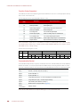
E1 AND E2 FEATURES AND SPECIFICATIONS
E1 Brain Board Features
The following table shows features available on an E1 digital I/O unit depending on the protocol used.
About E1 and E2 brain boards: You can configure E1s and E2s like any other I/O unit if you have E1/E2 firmware R1.2a
(and higher) and PAC Project 9.5000 (and higher). Also, if a SNAP PAC controller communicates with the E1 or E2, the
controller must have PAC firmware R9.5a (or higher) to use this simplified configuration method. If you are not using
these firmware and software versions (or if you prefer to use the previous method to reconfigure existing E1s or E2s),
see I/O Configuration for E1 an E2 Brain Boards (form 1576).
Each E1 feature is described below.
Read/Write to Point—The E1 can read the value of any input3 or output point and turn digital output points
on or off.
Input Latches—When the value of a digital input point changes from off to on, an on-latch can be set.
While the value of the point may return to off, the on-latch remains set until cleared, as a record of the change.
Similarly, an off-latch can be set when the value of a digital point changes from on to off, and it remains set
until cleared. See note 2 in the table above.
Latching is different on an E1 depending on the protocol used with the brain board. When the E1 is used with
the Optomux protocol, only one latch is available and you must configure it to be an off-to-on latch or
on-to-off latch. When you use an E1 with OptoMMP or Modbus/TCP, however, both types of latches are
automatically available for each point, and no configuration is required.
Counters—Digital input can be used as a counter, counting the number of times the input changes from off
to on.
Pulse Duration Measurement (using the Optomux protocol)—Any or all of the input points can function
as pulse duration timers. Either on or off pulses can be timed with a resolution of 10 milliseconds.
Pulse Generation (using the Optomux protocol)—The E1 can be instructed to output a specific number
of pulses (with programmable period) at any output point. Continuous square waves can also be generated.
Feature Optomux OptoMMP1Modbus/TCP
Read/write to point
Input latches 233
Counters4
Pulse duration measurement
Pulse generation
Time delays (10 ms resolution)
Watchdog timer
Networks
Serial (RS-422/485)
Ethernet
1 This protocol is also used with all PAC Project applications.
2 One latch per point is available; it can be configured as on-to-off or off-to-on.
3 Two latches per point are always available; no configuration is needed.
4 Maximum counter frequency is 400 Hz. Counters roll over at 65,535.

E1 AND E2 FEATURES AND SPECIFICATIONS
E1 and E2 User’s Guide
6
Time Delays (using the Optomux protocol)—Any or all output points can function in time delay mode.
Outputs can be set to operate with four types of delays:
•Delay before turning off
•Delay before turning on
•Pulse on
•Pulse off
Time delays are programmable with a resolution of 10 milliseconds.
Watchdog Timer—You can set a watchdog timer to monitor communication with the PC or other host
device. If the watchdog timer is set via the serial port, then any serial activity will trigger the watchdog
(including communications to other devices). If it is set via the Ethernet port, then only Ethernet activity
directed to the respective E1 or E2 will trigger the watchdog. If the watchdog isn’t triggered for the length of
time set, the brain board automatically sets designated I/O points to the values you have determined. This
action makes sure the process is brought to a safe state if communication fails.
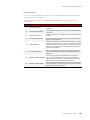
E2 Brain Board Features
The following table shows features available on an E2 I/O unit depending on the protocol used.
About E1 and E2 brain boards: You can configure E1s and E2s like any other I/O unit if you have E1/E2 firmware R1.2a
(and higher) and PAC Project 9.5000 (and higher). Also, if a SNAP PAC controller communicates with the E1 or E2, the
controller must have PAC firmware R9.5a (or higher) to use this simplified configuration method. If you are not using
these firmware and software versions (or if you prefer to use the previous method to reconfigure existing E1s or E2s),
see I/O Configuration for E1 an E2 Brain Boards (form 1576).
Each E2 feature is described below.
Read/Write to Point in Engineering Units (using OptoMMP)—The E2 can read the value of an input
point and send a value to an output point in engineering units, such as millivolts or milliamps.
Read/Write to Point in Counts—The E2 can read the value of an input point and send a value to an output
point in 12-bit counts.
This is especially useful when integrating with existing Optomux systems. The Optomux protocol will return
counts in a range of 0–4095.
Feature Optomux OptoMMP1Modbus/TCP
Read/write to point in Engineering units
Read/write to point in counts
Input averaging
Minimum/maximum values (peak/valley recording)2
High/low range testing
Offset and gain calculation
Waveform generation
Watchdog timer
Networks
Serial (RS-422/485)
Ethernet
1 This protocol is also used with all PAC Project applications.
2 If an ICTD or thermocouple module is used, minimum and maximum values are returned as counts.

CHAPTER 1: INTRODUCTION
E1 and E2 User’s Guide 7
The OptoMMP protocol returns counts based on how the E2 was configured:
•Modules configured directly as G1 modules (new method; requires E2 firmware R1.2a or higher and PAC
Project 9.5 or higher) will report counts as G1 counts (0–4095 nominal range).
•Modules configured as similar SNAP modules (old method using form 1576) will report counts as 0–
25000 or -25000 to +25000.
Input Averaging (using the Optomux protocol)—The E2 can be instructed to average the values of
successive readings.
Minimum/Maximum Values (peak/valley recording)—The E2 automatically keeps track of minimum and
maximum count values for each input. You can read these values at any time, and you can reset min/max
values.
NOTE: The values returned for temperature modules will be counts, not linearized temperature values. See Read/Write
to Point in Counts, above, for count values.
High/Low Range Testing—The E2 tests for the high and low limits (range) for the specified input points,
and sets a flag if values exceed the specified range
Offset and Gain Calculations—The brain board can calculate offset and gain for analog input points. If a
0 VDC to +5 VDC input receives signals that are slightly off (not exactly 0 VDC at the lowest point, for
example), the offset and gain can be calculated so that values will appear accurately.
NOTE: To calibrate analog points, use PAC Manager. See form #1714, the Legacy Edition PAC Manager User’s Guide.
Waveform Generation (using Optomux)—Square waves, triangle waves, and ramps can be generated at
any output point with programmable rates.
Watchdog Timer—You can set a watchdog timer to monitor communication with the PC or other host
device. If the watchdog timer is set via the serial port, then any serial activity will trigger the watchdog
(including communications to other devices). If it is set via the Ethernet port, then only Ethernet activity
directed to the respective E1 or E2 will trigger the watchdog. If the watchdog isn’t triggered for the length of
time set, the brain board automatically sets designated I/O points to the values you have determined. This
action makes sure the process is brought to a safe state if communication fails.

E1 AND E2 FEATURES AND SPECIFICATIONS
E1 and E2 User’s Guide
8
Specifications
Power Requirements 5.0–5.2 VDC @ 0.5 amps
(excludes digital and analog module power requirements) *
Ethernet Network Interface:
Type
Connector
Rate
Supported Protocols
Maximum Segment Length
IEEE 802.3 network, 10Base-T/100Base-TX
RJ-45: Supports Auto MDI-X (crossover cable not needed)
10/100 Mbps, half or full duplex
Optomux over Ethernet, Modbus/TCP, OptoMMP (Opto 22’s IEEE
1394-based memory-mapped protocol)
100 m (328 ft.) with Category 5 or superior UTP
Serial Network Interface:
Type
Connector
Data Rates
Supported Protocols
Network Range
RS-422/485 serial link
E1: Terminal block; E2: Terminal block (on mounting rack)
300, 600, 1200, 2400, 4800, 9600, 19200, and 38400 baud
Optomux
Up to 32 Optomux stations configured for multidrop can be used on a serial
network of up to 1524 m (5000 ft.) total length. Up to 256 Optomux stations
and longer line lengths can be used by installing network repeaters.
Up to 256 Optomux stations configured for repeat mode can exist
on a network.
Optomux I/O Functions
Digital I/O (E1): Read Point, Write Point, Latch Point (On/Off), Count,
Pulse Duration, Time Delay, Pulse Generation, Watchdog Timer
Analog I/O (E2): Read Point, Write Point, Input Averaging, Min/Max
Recording (peak and valley), High/Low Range Testing, Offset and Gain
Calculation, Waveform Generation, Watchdog Timer
Modbus/TCP, OptoMMP, and
OPC I/O Functions
With these protocols, the following brain-based features are not available:
• No pulsing or time delay (E1)
•
No pulse measurement
• No input averaging or waveform generation (E2)
LED Indicators Status, Link, Activity, Full duplex, Transmit (serial), Receive (serial)
Jumper-selectable Serial Options Group A: Multidrop or repeat mode, RS-485 termination and biasing
Group B: Serial address (0 to 255), baud rate, 2- or 4-pass protocol
Operating Temperature 0 °C to 70 °C
Storage Temperature –40 °C to 85 °C
Humidity 0–95% humidity, non-condensing
Agency Approvals DFARS
Warranty 30 months
* ±15 VDC ±0.25 V is required for the analog modules. Current depends on the number and types of modules
installed. A 24 VDC power supply is required for analog modules that need a current loop source.

CHAPTER 1: INTRODUCTION
E1 and E2 User’s Guide 9
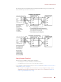
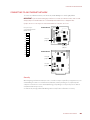
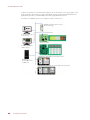
Dimensional Drawings
E1 Dimensions
E2 Dimensions

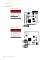
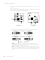
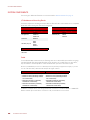
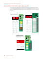
LED DESCRIPTIONS
E1 and E2 User’s Guide
10
LED DESCRIPTIONS
E1 LED Descriptions
E2 LED Descriptions
LED Description Link
Type
FD Full Duplex Mode Ethernet
ACT Network Activity Ethernet
LINK Link Ethernet
STAT Status n/a
REC Data Receive Serial
XMT Data Transmit Serial
LED Description Link
Type
LINK Network Link Ethernet
ACT Network Activity Ethernet
FDPX Full Duplex Mode Ethernet
STAT Status n/a
XMT Data Transmit Serial
RCV Data Receive Serial
ACT
LINK
STAT
REC
XMT
FD
FDPX
ACT
LINK
STAT
XMT
RCV

CHAPTER 1: INTRODUCTION
E1 and E2 User’s Guide 11
LED Blink Codes
The Status LED (STAT) on E1 and E2 brain boards provides both event and status information.
Code Type Meaning Comments
3 short blinks Event The brain board is
beginning to start up.
The LED starts to blink after the E1 or E2 is turned on or a
reboot command is sent to the device.
6 short blinks Event The brain board is
entering loader mode.
The LED starts to blink after the E1 or E2 is turned on or a
reboot command is sent to the device with the Loader
Mode Jumper installed.
LED on Status The brain board is run-
ning.
Once the brain board has started, the LED turns on and
stays on. This should occur shortly after a series of 3 short
blinks. Note that the color of the LED doesn't matter; as
long as the LED is On and not blinking, the brain board is
functioning normally.
LED flashing Status
The brain board is
restoring the factory
defaults or updating
the firmware.
CAUTION: DO NOT turn off power to the device while the
LED is flashing, even if it takes a very long time. Turning
off power might corrupt the firmware and the brain board
will not be able to start up. For more information, see
“Resetting the Brain Board to Factory Defaults” on
page 35 and “Loading New Firmware” on page 36.
Status
Status
LED
LED
E1 Brain Board E2 Brain Board

LED DESCRIPTIONS
E1 and E2 User’s Guide
12

E1 and E2 User’s Guide 13
13
Chapter 2
2: Installation
Use this chapter to install E1 and E2 brain boards. If you need more information on how to integrate E1s and
E2s with your system, see Chapter 3: Architecture and Communication.
WHAT YOU WILL NEED
To install an E1 or E2, you need the following items:
•PC running Microsoft® Windows® 2000 or higher, with a 10/100 MB Ethernet adapter card, the TCP/IP
protocol installed, and a valid IP address. The PC must be on the same subnet as the brain board.
•Serial cable for a serial network. For an Ethernet network, use Category 5 Ethernet cable. (For more
information on cables, see page 22.)
•E1 or E2 brain board
•I/O modules and mounting racks (See compatible I/O modules and mounting racks on page 22.)
•Power supply (See page 23.)
•Voltmeter
•Screwdriver
INSTALLING SOFTWARE
The software for E1 and E2 brain boards is available on the Opto 22 website.
•The E1 product page lists all E1 software in the Downloads tab.
•The E2 product page lists all E2 software in the Downloads tab.
MOUNTING THE BRAIN BOARD
Racks vary in shape and design. The combination of rack, modules, and brain board (called the I/O unit) can be
mounted in any attitude on any flat surface.
To ensure reliable and trouble-free communications, the following is recommended:
•Use twisted-pair wires for the serial communications wiring. See page 22.
•Keep communication and DC power wiring separate from any high-voltage field wiring.
Steps for mounting:
1. If you are replacing an existing B1 or B2 brain board, turn off the power to the rack and carefully remove
the B1 or B2 from the rack.
2. Carefully plug the E1 or E2 brain board into the mounting rack using the 50-pin connector.

MOUNTING THE BRAIN BOARD
E1 and E2 User’s Guide
14
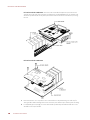
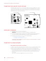
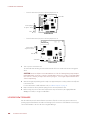
E1 brain board/rack combination. As shown in the G1/Standard example below, the brain board
extends out past the end of the rack when used with G4, G1, and Quad Pak I/O racks. For integral racks,
which have permanent I/O circuitry built in, the brain board is inserted in the other direction, covering
the rack.
E2 brain board/rack combination
3. Place the I/O unit as close as possible to the controlled device to minimize wiring costs and noise for
analog modules. When installing units next to each other, leave sufficient space between units for wiring.
4. For maximum physical strength, secure the brain board’s permanently attached standoffs. Also secure
standoffs on the rack, if available.
Page is loading ...
Page is loading ...
Page is loading ...
Page is loading ...
Page is loading ...
Page is loading ...
Page is loading ...
Page is loading ...
Page is loading ...
Page is loading ...
Page is loading ...
Page is loading ...
Page is loading ...
Page is loading ...
Page is loading ...
Page is loading ...
Page is loading ...
Page is loading ...
Page is loading ...
Page is loading ...
Page is loading ...
Page is loading ...
Page is loading ...
Page is loading ...
Page is loading ...
Page is loading ...
Page is loading ...
Page is loading ...
Page is loading ...
Page is loading ...
Page is loading ...
Page is loading ...
Page is loading ...
Page is loading ...
Page is loading ...
Page is loading ...
Page is loading ...
Page is loading ...
Page is loading ...
Page is loading ...
Page is loading ...
Page is loading ...
Page is loading ...
Page is loading ...
Page is loading ...
Page is loading ...
Page is loading ...
Page is loading ...
Page is loading ...
Page is loading ...
Page is loading ...
Page is loading ...
Page is loading ...
Page is loading ...
Page is loading ...
Page is loading ...
Page is loading ...
Page is loading ...
Page is loading ...
Page is loading ...
Page is loading ...
Page is loading ...
Page is loading ...
Page is loading ...
Page is loading ...
Page is loading ...
Page is loading ...
Page is loading ...
Page is loading ...
Page is loading ...
Page is loading ...
Page is loading ...
Page is loading ...
Page is loading ...
-
 1
1
-
 2
2
-
 3
3
-
 4
4
-
 5
5
-
 6
6
-
 7
7
-
 8
8
-
 9
9
-
 10
10
-
 11
11
-
 12
12
-
 13
13
-
 14
14
-
 15
15
-
 16
16
-
 17
17
-
 18
18
-
 19
19
-
 20
20
-
 21
21
-
 22
22
-
 23
23
-
 24
24
-
 25
25
-
 26
26
-
 27
27
-
 28
28
-
 29
29
-
 30
30
-
 31
31
-
 32
32
-
 33
33
-
 34
34
-
 35
35
-
 36
36
-
 37
37
-
 38
38
-
 39
39
-
 40
40
-
 41
41
-
 42
42
-
 43
43
-
 44
44
-
 45
45
-
 46
46
-
 47
47
-
 48
48
-
 49
49
-
 50
50
-
 51
51
-
 52
52
-
 53
53
-
 54
54
-
 55
55
-
 56
56
-
 57
57
-
 58
58
-
 59
59
-
 60
60
-
 61
61
-
 62
62
-
 63
63
-
 64
64
-
 65
65
-
 66
66
-
 67
67
-
 68
68
-
 69
69
-
 70
70
-
 71
71
-
 72
72
-
 73
73
-
 74
74
-
 75
75
-
 76
76
-
 77
77
-
 78
78
-
 79
79
-
 80
80
-
 81
81
-
 82
82
-
 83
83
-
 84
84
-
 85
85
-
 86
86
-
 87
87
-
 88
88
-
 89
89
-
 90
90
-
 91
91
-
 92
92
-
 93
93
-
 94
94


Ask a question and I''ll find the answer in the document
Finding information in a document is now easier with AI
Related papers
-
OPTO 22 B2 User guide
-
-
-
-
-
-
-
-
-
Other documents
-
Allen-Bradley DF1 User manual
-
-
PT PT200 Owner's manual
-
FieldServer FS-8700-17 User manual
-
Schneider Electric AP9635 Installation guide
-
Digi BL1000 User manual
-
National Instruments FP-1001 User manual
-
FW Murphy MX4 Series User manual
-
Mircom LT-6633 OpenBAS-HV-NXCORE Installation guide
-