Zip 2.8kW Single lever mixer tap instantaneous handwash pack User manual
- Type
- User manual
This manual is also suitable for
- 2.8kW Electronic instantaneous water heater
- 2.8kW Non-concussive tap instantaneous handwash pack
- 4.4kw Electronic instantaneous water heater
- 4.4kW Non-concussive tap instantaneous handwash pack
- 4.4kW Single lever mixer tap instantaneous handwash pack
- 5.5kW Electronic instantaneous water heater
- 5.5kW Non-concussive tap instantaneous handwash pack
- 5.5kW Single lever mixer tap instantaneous handwash pack

ES3, ES4 & ES6 Instructions. V1.09 Page 1 November / 2015
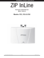
ZIP InLine
Electronic Instantaneous
Water Heaters
Models: ES3, ES4 & ES6
Installation & User Instructions

ES3, ES4 & ES6 Instructions. V1.09 Page 2 November / 2015
Please leave these instructions with the end user after installation.
To ensure you have the latest revision of this instruction manual, please visit www.zipheaters.co.uk
to download the latest copy.
In order to preserve our environment we ask that you dispose of this product correctly.
Please contact Zip Customer Service for advice on 0845 6 005 005 or 0345 6 005 005
Contents
Description 3
Approvals 3
Safety information 4
WARNING 4
CAUTION 5
Dimensions 5
Technical data 6
Spare Parts 7
Installation 8
Requirements 8
Installation site 8
Installing the appliance 9
Plumbing connection 10
Electrical connection / wiring diagram 12
Commissioning 12
Operation / Temperature & flow adjustment 13 - 14
Maintenance and cleaning 14 - 15
Fault finding 16
Warranty 17
WARNING: Situations that could cause injury to yourself or others.
CAUTION: Situations that could cause damage to your appliance or other equipment.
NOTE: Notes, usage tips or additional information.
IMPORTANT:
PLEASE READ THESE INSTRUCTIONS CAREFULLY.
NOTE THE SAFE OPERATIONAL REQUIREMENTS, WARNINGS AND CAUTIONS. USE THIS PRODUCT
CORRECTLY AND WITH CARE FOR THE PURPOSE FOR WHICH IT IS INTENDED. FAILURE TO DO
SO MAY CAUSE DAMAGE AND/OR PERSONAL INJURY, AND WILL INVALIDATE THE WARRANTY.
RETAIN THESE INSTRUCTIONS FOR FUTURE USE.
Index

ES3, ES4 & ES6 Instructions. V1.09 Page 3 November / 2015
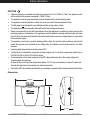
Description
Zip InLine ES3, ES4 and ES6 instantaneous water heaters are compact electronically controlled
instantaneous water heaters for hand washing.
This small instantaneous water heater is intended to provide economical heating of water for
a wash basin when installed together with a sanitary water fitting. When the hot-water tap
is opened, the heater switches itself on automatically when the minimum water flow rate is
exceeded and heats the water as it passes through the appliance.
The heater is pre-set in the factory to an outlet temperatu re of about 38°C, which is ideal for
hand washing. When this temperature is reached, the electronic regulator reduces the power
in order to ensure that the outlet temperature does not exceed this value. This automatic
temperature regulation means that it is only necessary to open the hot water tap to obtain
water at a constant, safe temperature for washing hands. If the set outlet temperature is not
reached, slightly reduce the flow of water from the tap. Cold water may be added if a lower
temperature is required.
If the flow rate is too low or if the hot water tap is closed, the appliance switches itself off
automatically. For an optimum flow of water, always fit the special jet regulator supplied with
the appliance. This regulator should be inserted into the threaded retainer on the tap outlet.
The maximum possible outlet temperature is determi ned by the temperature of the incoming
water, the flow rate and the heating power of the heater.
The temperature set point and flow rate can be preset inside the appli ance to achieve an
outlet temperature between about 30°C and 43°C.
Power consumption is also regulated based on outlet temperature to ensure the required
temperature is achieved exactly to the degree and irrespective of fluctuations in voltage and
water pressure.
The maximum inlet temperature of 70°C is suitable for use with preheated water e.g. from solar
heating systems.
Approvals
Zip InLine ES3, ES4 and ES6 are VDE approved to the LVD and EMC directives and CE endorsed.
Zip InLine ES3, ES4 and ES6 have been examined, tested and found when correctly fitted to
comply with the requirements of the United Kingdom Water Regulations / Byelaws (Scotland).
The products are listed under the WRAS (Water Regulations Advisory Scheme) Water Fittings
and Materials Directory.
Index General Product Description

ES3, ES4 & ES6 Instructions. V1.09 Page 4 November / 2015
WARNING
• Installation, commissioning and maintenance of this appliance must only be carried
out by a competent installer who will then be responsible for adhering to all relevant
standards and regulations.
• The front cover of the appliance must never be opened before disconnecting the
appliance from the mains power supply.
• To protect the appliance, a circuit breaker or fuse must be fitted with a rating suitable for the
nomi nal current of the appliance.
• The appliance must be permanently connected to the supply through an isolating switch with a
contact separation of at least 3mm in all poles and be protected by a suitably rated RCD.
• The cross sectional area of the connection cable must be appropriate for the power rating and
location of the appliance (See Technical Data Section on page 6).
• The connecting cable must be adequately secured.
• This appliance must be earthed at all times.
• Check that the power supply is switched off prior to electrical connection.
• The appliance, its wiring and piping must not be modified in any way.
• In case of malfunction isolate the power supply immediately. In case of leaks also isolate the
water supply. Repairs must only be carried out by Zip Heaters (UK) Ltd or an authorised Zip
service engineer.
• Temperatures in excess of approximately 43°C are perceived as hot, especially by children, and
may cause a feeling of burning.
• This appliance can be used by children aged from 8 years and above and persons with
reduced physical, sensory or mental capabilities or lack of experience and knowledge if they
have been given supervision or instruction concerning the use of the appliance in a safe way
and understand the hazards involved.
Children shall not play with the appliance.
Cleaning and user maintenance shall not be made by children without supervision.
• When the appliance has been in use for some time, the fittings may be very hot.
• If inlet temperature is up to 70°C (eg. fed from a solar supply) mixing with cold water will be
required to ensure a safe temperature at the outlet.
Safety Information
Safety Information

ES3, ES4 & ES6 Instructions. V1.09 Page 5 November / 2015
CAUTION
• Optimum operation is ensured at a water flow pressure of 0.2 to 0.4 MPa (2-4 bar). The appliance must
not be subjected to pressure exceeding 1.0 MPa (10 bar).
• The appliance must only be used when correctly installed and in perfect working order.
• The appliance must be installed in a frost-free room and must never be exposed to frost.
• The ES range is not intended for use with thermostatic mixing valves or taps.
• The appliance must be completely filled with water before being switched on.
• Before commissioning for the first time and each time the appliance is emptied (e.g. due to work on the
plumbing system or maintenance), the appliance must be vented by opening and closing the hot water
tap until all air has been eliminated from the water heater and no more air emerges before re-connecting
to the electrical supply.
• The appliance must only be used for heating potable water. The specific water resistance must not fall
below the required value indicated on the rating plate. The appliance must not be used for any other
purpose.
• Incoming water temperature must not exceed 70°C.
• The Zip InLine is intended for connection to mains supply only. In any other case please contact Zip on
0845 6 005 005 or 0345 6 005 005 for advice.
• The temperature of hot water produced by the ES is dependant upon flow rate, supply voltage and
incoming water temperature.
At times of low incoming water temperature (below 12°C) it may be necessary to reduce the flow rate
through the appliance to increase the hot water temperature.
• Zip Heaters (UK) Ltd cannot be held liable for any damages caused by failure to observe these instructions.
186mm
135mm
87mm
Dimensions
Safety Information

ES3, ES4 & ES6 Instructions. V1.09 Page 6 November / 2015
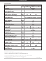
Zip InLine
Model ES3 ES4 ES6
Installation Underbasin
Declared load profile XXS
Energy efficiency class (1) A
Energy efficiency (ηwh)(1) [%] 39
Annual electricity consumption (1) [kWh] 478 475
Thermostat temperature setting [°C] 43
Specific precautions See installation and operating instructions
“Smart” value 0
Sound power level [dB(A)] 15
Rated volume [l] 0.2
Weight empty / full [kg] 1.3/1.5
Nominal supply voltage [V~] 230
Power rating [kW] 2.8 4.4 5.5
Rated current [A] 12 19 24
Protection class IP25
Element type Bare wire
Rated pressure [MPa] 1.0
Factory set temperature (2) [°C] 38
Temperature adjustment range [°C] 30-43
Maximum inlet temperature [°C] 70
Factory set flow rate @3 bar [l/min] 2.0 2.5 3.3
Switch on flow rate [l/min] 1.2 1.5
Switch off flow rate [l/min] 1.0 1.3
Flow rate @ 38°C(3) [l/min] 1.5 2.4 3.0
Minimum differential pressure @ 38°C [MPa] 0.020 0.045 0.065
Specific water resistance @ 15°C [Ω.cm] >1,100 >800
Packaging dimensions [mm] 225 x 190 x 130
Water connections 1/2” BSP
Technical data
(1) EU Regulation 812/2013, 814/2013
(2) Subject to incoming water temperature, flow rate and power available.
(3) Based on 12°C supply temperature, 3 bar dynamic pressure and nominal 230V supply voltage.
All data quoted at nominal supply voltage. Standard European voltage tolerances of -6% to +10% may be applied.
A minimum water pressure of 0.2 MPa (2 bar) is recommended for optimum performance.
Technical Data Spare Parts

ES3, ES4 & ES6 Instructions. V1.09 Page 7 November / 2015
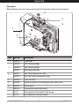
Item Part No. Description
1 IN80919 Front cover
2
IN80916 ES3 Heating cartridge
IN80904 ES4 Heating cartridge
IN80917 ES6 Heating cartridge
3IN80911 ES3 Safety Temperature limiter
IN80912 ES4, ES6 Safety Temperature limiter
4 IN80080 Filter (fine filter)
5 IN80909 Water connection set, including two water connections
6 IN80902 Wall bracket
IN80910 Temperature sensor (Not shown)
ZL011 Jet regulator for ES3 and ES4 (Not shown)
ZL010 Jet regulator for ES6 (Not shown)
Spare parts.
1
2
3
4
5
6
When ordering spare parts, please always specify the appliance model and serial number.
Spare Parts

ES3, ES4 & ES6 Instructions. V1.09 Page 8 November / 2015
Installation
Requirements
• These instructions must be read and fully understood before commencing the installation. If in
doubt, or in need of further guidance please ring Zip on 0845 6 005 005 or 0345 6 005 005.
• Zip InLine water heaters must be installed by a competent person familiar with electric
instantaneous water heaters.
• Installations must comply fully with UK Water Regulations and any Local Authority requirements.
• The electrical installation including earthing and cross bonding should comply with current IEE
regulations and any Local Authority requirements.
• Zip InLine water heaters must be installed according to the specification on the rating plate and
the technical specifications.
• To protect the appliance, a circuit breaker or fuse must be fitted with a rating suitable for
the nomi nal current of the appliance. (See Technical Data Section on page 6).
• The appliance must be permanently connected to the supply through an isolating switch
with a contact separation of at least 3mm in all poles and be protected by a suitably rated
RCD.
• The cross sectional area of the connection cable must be in accordance with the power
rating of the appliance and the specific requirements of the installation site.
• Take care to protect the wiring from damage during installation and ensure that any
uninsulated wiring is not directly accessible after installation.
• Check that the power supply is switched off prior to electrical connection.
Installation site
• The installation site must be free from frost at all times.
• For maintenance work a shut off valve should be installed in the water supply line to the
heater.
• The unit should be positioned as close as possible to the outlet to minimise heat loss. The
recommended maximum distance is 0.5 metres.
• When considering the location of the heater, consideration should be given to the safe and
visible disposal of any water resulting from leaks and seepage.
This is particularly relevant when the heater is located in a cupboard or any concealed
location.
• For guidance please call Zip Heaters (UK) Ltd on 0845 6 005 005 or 0345 6 005 005.
• Hot and cold water connecting pipes should be WRAS approved and of copper or steel
construction. Plastic pipes may only be used if conforming to DIN 16893 Series 2.
• The specific resistance of the supply water must be >1,100Ωcm at 15°C for ES3 and
>800Ωcm at 15°C for ES4 and ES6. The specific resistance can be checked with the local
water supply company.
Installation Installation

ES3, ES4 & ES6 Instructions. V1.09 Page 9 November / 2015
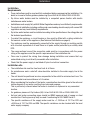
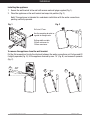
Fig. 2
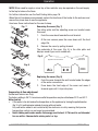
Installing the appliance
1. Secure the wall bracket to the wall with screws and wall plugs supplied (Fig. 1).
2. Place the appliance on the wall bracket and snap into position (Fig. 2).
Note! This appliance is intended for underbasin installation with the water connections
pointing vertically upwards.
Fig. 1
Drill size Ø 7mm.
Use the mounting bracket as
a guide for fixing marks.
Drilling width variable:
100mm minimum to
145mm maximum.
To remove the appliance from the wall bracket.
Put the flat screwdriver tip into the interlock between the water connections unil it stops and lift
it slightly upwards (Fig. A), tilt the appliance forward by max. 15° (Fig. B) and remove it upwards
(Fig. C).
A
BC
Installation

ES3, ES4 & ES6 Instructions. V1.09 Page 10 November / 2015
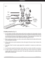
Seal
Seal
Hot Water
Connection
(outlet)
Filter
Cold Water
Connection
(inlet)
Fig. 3
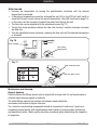
Plumbing connection (Fig. 3)
1. The cold water inlet (blue) and hot water outlet (red) are marked on the rating plate. Connect
the appropriate pipes from the tap to the water inlet and outlet accordingly. Avoid exerting
any mechanical pressure on the appliance by applying a 13mm spanner on the flats of the
inlet and outlet connections when tightening the pipe connectors (Fig.3).
2. When supplying mixer taps a non-return valve must be fitted to the hot water outlet and not
to the cold water inlet (fig. 5).
3. A flow control valve may be required on the cold supply to the mixer taps to balance the
flow (fig. 5).
4. Thoroughly flush the water supply pipes brfore connection to remove any water borne
debris.
5. Once the water connections have been made, check for any leaks and rectify as necessary.
6. In order to obtain an optimum water jet at low flow rates, always screw the jet regulator
supplied with the unit onto the tap outlet. This insert fits commercially available sleeves
with an M22 or M24 thread.
Installation Installation

ES3, ES4 & ES6 Instructions. V1.09 Page 11 November / 2015
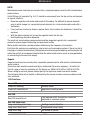
Typical installation
Fig. 4/5 show unvented installation
with closed outlet tap.
Fig. 4a shows open vented installation
Fig. 4
You may also use an open
vented installation.
Fig. 4a
Fig. 5
Service Valve
Flow Control Valve
Mains Supply
Fit Jet Regulator
Jet Regulator
Rear Cable Entry
Non-return
valve
Installation

ES3, ES4 & ES6 Instructions. V1.09 Page 12 November / 2015
Electrical connection
Do not switch on the electric power at this time.
Installation must be carried out by a competent electrician.
The electrical installation including earthing and cross bonding should comply with current IEE
regulations and any Local Authority requirements.
IMPORTANT: The appliance must be installed according to the specification on the rating plate
and the technical specifications. Ensure that the voltage marked on the appliance matches the
power supply.
WARNING: Check that the power supply is switched off prior to electrical connection!
Fig. 6
3
2
1
Wiring Diagram
1. Electronic regulator
2. Safety thermal cut-out
3. Heating element
PE
L L1
N L2
Commissioning
CAUTION
To prevent damage to the appliance, the instantaneous water heater must be purged of
air before using it for the first time.
PURGING
Before connecting the electrical supply, open and close the hot water tap until the water runs
smoothly and no more air emerges.
NOTE! Every time the appliance is drained (e.g. after work on the plumbing system, if
there is a risk of frost or following repair work), the heater must be purged in this way
before reconnecting the power supply.
WARNING! This appliance must be earthed.
1. Close the circuit breaker to connect the electrical supply. After a short power up delay the
water heats up.
2. Check everything is working as it should and the water temperature is achieving the desired
temperature. If not follow the guide on pages 13/14.
Electrical Installation
Commissioning

ES3, ES4 & ES6 Instructions. V1.09 Page 13 November / 2015
NOTE! When used to supply a mixer tap a flow restrictor may be required on the cold supply
to the tap to balance the flows.
For further information see the Fault Finding table, page 16.
When the unit has been commissioned, explain the functions of the heater to the end user and
ensure they know how to use the appliance.
Hand over these instructions for the user to keep.
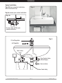
Removing the cover (Fig. 7)
The rating plate and the adjusting screw are located under
this cover.
1. Push the cover back towards the wall bracket.
2. At the rear corners press the cover down until the front
edge lifts.
3. Remove the cover by pulling forward.
The underside of the cover (Fig. 8) is the data plate and
displays model type, serial number etc.
Replacing the cover (Fig. 9)
1. Push the cover towards the wall bracket under the edges
of the water connections.
2. Press down the front edge of the cover and move it
forward again until it clips into place.
Fig. 8
Fig. 9
Fig. 7
Appliance must be earthed!
Zip Industries
ES3 1500-15001
012345-012345
MADE IN
GERMANY
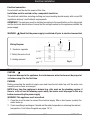
Temperature & flow adjustment
(Authorised Technicians Only)
The factory setting is 38°C. A maximum outlet temperature may be set between 30°C and 43°C.
Water too hot
• If the water is too hot reduce the temperature on the appliance by turning the potentiometer
(fig.10 p14) anticlockwise instead of mixing with cold water.
Any cold water added is not controlled by the electronic circuitry meaning that precise
temperature control can no longer be guaranteed.
• Note! Adding cold water wastes the energy used to heat it! This unit is not intended
for use with a ‘thermostatic mixing valve’ or tap.
Operation

ES3, ES4 & ES6 Instructions. V1.09 Page 14 November / 2015
Cover removed
Water too cold
• Increase the temperature by turning the potentiometer clockwise until the desired
temperature is achieved.
• If the desired temperature cannot be achieved the red LED on the PCB will light (solid) to
show that the unit cannot achieve the preset temperature. (See LED functions on page 15).
• In this case it will be necessary to adjust the water flow through the unit.
• The flow rate can be adjusted with the adjustment screw (Fig. 11).
• Turning this screw clockwise reduces the flow rate; turning it counter-clockwise increases
the flow rate.
• Turn the adjustment screw clockwise; reducing the flow rate until the desired temperature
is achieved.
Fig. 11
Fig. 10
Cover retaining screw
Flow rate adjust screw
Direction Flow
-
+
min. max.
Green LED
Heat setting
potentiometer
Maintenance and cleaning.
General cleaning
Plastic surfaces and fittings should only be wiped with a damp cloth. Do not use abrasive or
chlorine-based cleaning agents or solvents.
The outlet fittings (special tap aerators and shower heads) should be
unscrewed and cleaned at regular intervals.
The electrical and plumbing components should be inspected at least every 3 years by a
competent person familiar with instantaneous water heaters, to ensure proper functioning
and operational safety . Water quality should be considered when determining the frequency
of inspection.
Red LED
Maintenance
Operation

ES3, ES4 & ES6 Instructions. V1.09 Page 15 November / 2015
NOTE!
Maintenance work must only be carried out by a competent person familiar with instantaneous
water heaters.
Outlet fittings (jet regulator Fig. 5 p11) should be unscrewed from the tap nozzle and cleaned
at regular intervals.
• Rinse the regulator with water and brush off the debris. For difficult to remove deposits,
soak in white vinegar (or a proprietary scale cleaner) for a few minutes and scrub with a
toothbrush.
• If any parts are cracked or broken, replace them. If the washer has hardened, it should be
replaced.
• With the debris cleaned out, screw the regulator back into the tap.
Hand tightening should be adequate.
The electrical and plumbing components should be inspected regularly by a competent
person to ensure proper functioning and operational safety.
Water quality should be considered when determining the frequency of inspection.
Each time the appliance is emptied (e.g. due to work on the plumbing system, if there is a risk of
freezing or in case of maintenance), the appliance must be purged by opening and closing the hot
water tap until all air has been eliminated from the water heater and no more air emerges before
re-connecting to the electrical supply.
Repairs
Repairs should only be carried out by competent persons familiar with electric instantaneous
water heaters.
All service work should be performed by an authorized Zip service engineer – for details of
the full range of services available call Zip Service on: 0845 6 005 005 or 0345 6 005 005.
When calling for service, please always specify the appliance model and serial number.
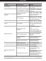
The following table will be helpful in determining the causes of some common problems and
their solutions
LED Functions
Green LED
Green LED flashing Standby mode
Green LED constantly on Appliance is heating water
Red LED
Red LED constantly on The required outlet temperature cannot be
achieved at maximum power
Red LED flash code:
Long- short-long-short-long Heating element defective
Long-short-short-short Temperature sensor faulty
Long-short-long Air bubble in system
MaintenanceOperation

ES3, ES4 & ES6 Instructions. V1.09 Page 16 November / 2015
Problem Possible cause Solution
No water flows Water supply is turned off Open the main water valve /
shut off valve
Water flows more slowly than
expected
The Jet Regulator is not fitted Fit the correct Jet Regulator
(see Fig. 5)
Water pressure is not
sufficient
Check the water flow
pressure, check the water flow
adjustment. See fig. 11
Dirt in the pipes
Remove any dirt from the
filter, valves and / or taps,
check the technical data
The heater switches itself on
and off
Water pressure is varying, flow
rate is too low
Remove any dirt, increase
the flow water pressure, close
other taps, open the shut off
valve further
Water remains cold
Water pressure is not
sufficient
Adjust the water flow see
fig. 11
Open the shut-off valve.
Fit the correct jet regulator (see
Fig. 5) check water pressure
Dirt in the inlet or outlet Remove dirt from the inlet
and outlet
Temperature sensor
defective
Replace temperature sensor
(authorised technician)
Heating element defective Replace heating element
(authorised technician)
Hot water temperature varies Supply voltage varies Check the supply voltage
Water connections reversed Check installation
Hot water temperature too
low
Flow rate is too high
Inlet temperature is too low
Adjust the flow rate
(see adjusting flow rate on
page 13 fig. 11)
Adjust temperature
potentiometer. (see adjusting
potentiometer page 13 fig. 10)
(Authorised technician)
Fault Finding Warranty
End of Life Disposal

ES3, ES4 & ES6 Instructions. V1.09 Page 17 November / 2015
The Zip appliance you have chosen is precision-built from the finest materials available and should
give many years of trouble free service.
Certain warranties may be implied by law into your contract with Zip.
The
warranty provided below is additional to these implied warranties and
nothing
set out below
shall limit your statutory rights or rights at law.
Zip Heaters (UK) Ltd warrants that, should any part fail within 12
calendar
months of installation,
that part will be repaired or replaced free of charge by
Zip
or
its Distributor or Service Provider,
except as set out below, provided
the
appliance is installed and used strictly in accordance with
the
instructions
supplied, and that failure is not due to accident, misuse, abuse,
unsuitable
water
conditions, or to any alteration, modification or repair by any party
not
expressly nominated by
Zip.
No costs are payable by the customer other than any mileage or
travelling-time
charges incurred
by a Zip Service Provider or the cost of removal, cartage
and
re-installation of any component of
the appliance if it needs to be returned
for
repair to Zip or its Distributor.
This warranty does not cover damage resulting from non-operation of
the
appliance or consequential
damage to any other goods, furnishings or property.
Zip does not exclude, restrict or modify any liability that cannot be
excluded,
restricted or modified
or which cannot, except to a limited extent, be
excluded,
restricted or modified as between the
owner or user and Zip under the
laws
applicable.
Furthermore, this warranty does not displace any statutory warranty, but, to
the
extent to which Zip
is entitled to do so, the liability of Zip under any
statutory
warranty will be limited at Zip’s option
to the replacement of the appliance
or
supply of equivalent appliance, the payment of the cost of
replacing
the
appliance or acquiring an equivalent appliance, or the payment of the cost of having
the appliance repaired or the repair of the
appliance.
Warranty
NOTE: It is our policy to continually improve products and as such we reserve the right to alter data,
specifications and component parts without prior notice.
To ensure you have the latest revision of this instruction manual, please visit www.zipheaters.co.uk to
download the latest copy.
IMPORTANT: No liability is accepted for incorrect use of this product.
The use of this crossed out wheeled bin logo indicates that this product needs to be
disposed of separately to any other household waste.
Within each of the European Union member countries, provisions have been made
for the collection and recycling of unwanted electrical and electronic equipment.
In order to preserve our environment we ask that you dispose of this product
correctly.
Please contact Zip Customer Service for advice on
0845 6 005 005 or 0345 6 005 005.
Warranty
End of Life Disposal

ES3, ES4 & ES6 Instructions. V1.09 Page 18 November / 2015
Notes

ES3, ES4 & ES6 Instructions. V1.09 Page 19 November / 2015
Notes

ES3, ES4 & ES6 Instructions. V1.09 Page 20 November / 2015
Zip Heaters (UK) Ltd
14 Bertie Ward Way
Dereham
Norfolk
NR19 1TE
Telephone: 0845 6 005 005
Mobile: 0345 6 005 005
Fax: 01362 692448
Web: www.zipheaters.co.uk
The terms ‘Zip’ and ‘InLine’
are registered trademarks
999120-14111
-
 1
1
-
 2
2
-
 3
3
-
 4
4
-
 5
5
-
 6
6
-
 7
7
-
 8
8
-
 9
9
-
 10
10
-
 11
11
-
 12
12
-
 13
13
-
 14
14
-
 15
15
-
 16
16
-
 17
17
-
 18
18
-
 19
19
-
 20
20


Zip 2.8kW Single lever mixer tap instantaneous handwash pack User manual
- Type
- User manual
- This manual is also suitable for
-
- 2.8kW Electronic instantaneous water heater
- 2.8kW Non-concussive tap instantaneous handwash pack
- 4.4kw Electronic instantaneous water heater
- 4.4kW Non-concussive tap instantaneous handwash pack
- 4.4kW Single lever mixer tap instantaneous handwash pack
- 5.5kW Electronic instantaneous water heater
- 5.5kW Non-concussive tap instantaneous handwash pack
- 5.5kW Single lever mixer tap instantaneous handwash pack
Ask a question and I''ll find the answer in the document
Finding information in a document is now easier with AI
Related papers
-
Zip InLine Instantaneous Hot Water heater 3kW User manual
-
-
Zip InLine Instantaneous Hot Water handwash kit 3kW User manual
-
-
-
-
Zip Aquapoint 4 Smart unvented 100 Litre wall mounted water heater User manual
Other documents
-
Banner ES-TA-3F1 Operating Instructions Manual
-
 Stern Underbasin Thermostatic Mixing Valve Installation guide
-
 Cajun Injector Electric Smoker Owner's manual
-
Alto FLOORTEC R 570 P User manual
-
Pego EASYSTEAM Use and Maintenance Manual
-
-
Hyco Ara User manual
-
Cobra DCX65 2003 Owner's And Service Manual
-
-
Curtis GEMXSIFT63A1000 User guide

