Page is loading ...

DKG-225 User Manual Firmware V-01
DKG-225
AUTOMATIC MAINS
FAILURE UNIT
WITH INTERNAL
CHARGER
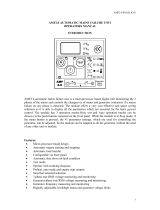
DKG-225, is a low cost AMF controller for 12V gensets,
featuring an internal battery charger. Internal fuel and
crank relays are rated at 40Amps@12V-DC and do not
require external relays.
Thus a typical transfer panel will simply consist on one
DKG-225 and two contactors, reducing material cost,
panel size and production time.
The unit supports also current transformer connections
allowing detailed power measurements from both mains
and genset sides. The standard unit supports 1A and
5A secondary CTs. A special version supports low cost
and small 0.1A secondary CTs allowing more compact
panel design.
Thanks to the DKG-225, automatization of small
gensets has become easy and cost effective.
In AUTO position, the unit monitors 3 phases of the
mains, runs and stops the genset automatically and
performs load transfer. When the engine is running, it
monitors internal protections and alarm inputs.
The 1Amp @12V-DC rated battery charger is sufficient
for the float charging of the engine start battery.
Timers, threshold levels, input and output configurations
are digitally programmable. Programs are modified
through front panel pushbuttons and do not require an
additional unit.
The fault conditions are considered in 2 categories as
Warnings and Alarms. Measured values have separate
programmable limits for warning and alarm conditions.
The unit is designed for front panel mounting.
Connections are made with 2 part plug and socket
connectors.
• Automatic mains monitoring
• Automatic load transfer
• Automatic starting and stopping
• Automatic stopping in fault condition
• Gas engine support
• Test mode available
• Emergency backup mode
• 3 phase mains voltage inputs
• 3 phase genset voltage inputs
• 3 phase mains/genset CT inputs
• 2 configurable analog sender inputs
• 3 configurable digital inputs
• Detailed AC measurements and protections
• Internal battery charging rectifier
• 40 Amp rated Fuel and Crank outputs
• Front panel adjustable parameters
• Stop, preheat and choke output capability
• Survives cranking voltage dropouts
• Compact dimensions, panel mounted
Mains Volts: L1-N, L2-N, L3-N, L1-L2, L2-L3, L3-L1
Genset Volts: L1-N, L2-N, L3-N, L1-L2, L2-L3, L3-L1
Load Currents: L1, L2, L3
Load total kW, kVA, kVAr, cosΦ
Genset Frequency
Battery Voltage
Oil pressure
Coolant temperature
Engine run Hours
Service Counters
MEASUREMENTS
FEATURES
DESCRIPTION

DKG-225 User Manual Firmware V-01
- 2 -
Any unauthorized use or copying of the contents or any part of this document is prohibited.
This document describes minimum requirements and necessary steps for the successful installation of
the DKG-225 family units.
Follow carefully advices given in the document. These are often good practices for the installation which
reduce future issues.
For all technical queries please contact Datakom at below e-mail address:
If additional information to this manual is required, please contact the manufacturer directly at below e-
mail address: [email protected].tr
Please provide following information in order to get answers to any question:
- Device model name (see the back panel of the unit),
- Complete serial number (see the back panel of the unit),
- Firmware version (read from the display screen),
- Measuring-circuit voltage and power supply voltage,
- Precise description of the query.
REVISION
DATE
WRITTEN
DESCRIPTION
01
08.11.2016
MH
First edition
CAUTION: Potential risk of injury or death.
WARNING: Potential risk of malfunction or material damage.
ATTENTION: Useful hints for the understanding of device operation.
TERMINOLOGY
QUERRIES
REVISION HISTORY
ABOUT THIS DOCUMENT
COPYRIGHT NOTICE

DKG-225 User Manual Firmware V-01
- 3 -
Screw Type Bracket
Stock Code=J10P01 (1 unit)
Spring Type Bracket
Stock Code=K16P01 (1 unit)
Watertight Gasket, Stock Code= K96P01
SPARE PARTS

DKG-225 User Manual Firmware V-01
- 4 -
Electrical equipment should be installed only by qualified specialist. No
responsibility is assured by the manufacturer or any of its subsidiaries for
any consequences resulting from the non-compliance to these instructions.
Check the unit for cracks and damages due to transportation. Do not install
damaged equipment.
Do not open the unit. There are no serviceable parts inside.
Fuses must be connected to phase voltage inputs, in close proximity of the
unit.
Fuses must be of fast type (FF) with a maximum rating of 6A.
Disconnect all power before working on equipment.
When the unit is connected to the network do not touch terminals.
Short circuit terminals of unused current transformers.
Any electrical parameter applied to the device must be in the range
specified in the user manual. Although the unit is designed with a wide
safety margin, over-range parameters may reduce lifetime, alter operational
precision or even damage the unit.
Do not try to clean the device with solvent or the like. Only clean with a
dump cloth.
Verify correct terminal connections before applying power.
Only for FRONT panel mounting.
Current Transformers must be used for current measurement.
No direct connection allowed.
WARNING: Use of fuses of higher rating than allowed may
result in serious hazards.
SAFETY NOTICE
Failure to follow below instructions will result in
death or serious injury

DKG-225 User Manual Firmware V-01
- 5 -
1. INSTALLATION INSTRUCTIONS
2. MOUNTING
2.1 DIMENSIONS
2.2 SEALING, GASKET
2.3 ELECTRICAL INSTALLATION
3. TERMINAL DESCRIPTIONS
3.1. BATTERY VOLTAGE INPUT / OUTPUT
3.2. AC VOLTAGE INPUTS
3.3. AC CURRENT INPUTS
3.4. DIGITAL INPUTS
3.5. ANALOG SENDER INPUTS
3.6. CHARGE INPUT TERMINAL
3.7. MAINS CONTACTOR OUTPUT
3.8. GENERATOR CONTACTOR OUTPUT
3.9. DIGITAL OUTPUTS
4. CONNECTION DIAGRAM
5. TERMINAL DESCRIPTION
6. TECHNICAL SPECIFICATIONS
7. DESCRIPTION OF CONTROLS
7.1. FRONT PANEL FUNCTIONALITY
7.2. PUSHBUTTON FUNCTIONS
7.3. DISPLAY SCREEN ORGANIZATION
7.4. MEASURED PARAMETERS
7.5. LED INDICATORS
8. OPERATION OF THE UNIT
8.1. QUICK START GUIDE
8.2. STOP MODE
8.3. MANUAL RUN MODE
8.4. AUTO MODE
9. PROTECTIONS AND ALARMS
9.1. SERVICE REQUEST ALARM
9.2. ALARMS
10. PROGRAMMING
11. CRANK CUTTING
TABLE OF CONTENTS

DKG-225 User Manual Firmware V-01
- 6 -
12. SOFTWARE FEATURES
12.1. REMOTE START OPERATION
12.2. MAINS SIMULATION
12.3. DELAYED MAINS SIMULATION, BATTERY CHARGING
12.4. SERVICE REQUEST DISPLAY
12.5. ENGINE HOUR METER
12.6. SOFTWARE VERSION DISPLAY
12.7. GAS ENGINE FUEL SOLENOID CONTROL
12.8. SINGLE PHASE OPERATION
13. DECLARATION OF CONFORMITY
14. MAINTENANCE
15. DISPOSAL OF THE UNIT
16. ROHS COMPLIANCE
17. TROUBLESHOOTING
TABLE OF CONTENTS (continued)

DKG-225 User Manual Firmware V-01
- 7 -
Before installation:
Read the user manual carefully, determine the correct connection diagram.
Remove all connectors and mounting brackets from the unit, then pass the unit through the
mounting opening.
Put mounting brackets and tighten. Do not tighten too much, this can brake the enclosure.
Make electrical connections with plugs removed from sockets, then place plugs to their sockets.
Be sure that adequate cooling is provided.
Be sure that the temperature of the environment will not exceed the maximum operating
temperature in any case.
Below conditions may damage the device:
Incorrect connections.
Incorrect battery voltage.
Reverse battery voltage
Voltage at measuring terminals beyond specified range.
Voltage applied to digital inputs over specified range.
Current at measuring terminals beyond specified range.
Overload or short circuit at relay outputs
Excessive vibration, direct installation on vibrating parts.
Below conditions may cause abnormal operation:
Battery voltage below minimum acceptable level.
Frequency out of specified limits
Missing earthing
Current Transformers must be used for current measurement.
No direct connection allowed.
1. INSTALLATION INSTRUCTIONS

DKG-225 User Manual Firmware V-01
- 8 -
Dimensions: 133x107x46mm (5.25”x4.2”x1.9”)
Panel cutout: 117x87mm minimum (4.6”x3.43”)
Weight: 200g (0.45 lb)
87mm
117mm
WALL
40mmmin 60mm
Mount the unit on a flat, vertical surface. Before mounting, remove the mounting brackets and connectors
from the unit, then pass the unit through the mounting opening.
Place and tighten mounting brackets.
The unit is designed for panel mounting. The user should not
be able to access parts of the unit other than the front panel.
2.1. DIMENSIONS
2. MOUNTING

DKG-225 User Manual Firmware V-01
- 9 -
The module will come with one of below bracket types:
Screw type bracket
Spring type bracket
Screw type bracket installation
Spring type bracket installation
Do not tighten too much, this may break the unit.

DKG-225 User Manual Firmware V-01
- 10 -
The rubber gasket provides a watertight means of mounting the module to the genset panel. Together
with the gasket, IEC 60529-IP65 protection can be reached from the front panel. A short definition of IP
protection levels is given below.
1st Digit Description of Protection Level
0 Not protected
1 Protected against solid foreign objects of 50 mm diameter and greater
2 Protected against solid foreign objects of 12,5 mm diameter and greater
3 Protected against solid foreign objects of 2,5 mm diameter and greater
4 Protected against solid foreign objects of 1,0 mm diameter and greater
5 Protected from the amount of dust that would interfere with normal operation
6 Dust tight
2nd Digit Description of Protection Level
0 Not protected
1 Protected against vertically falling water drops
2 Protected against vertically falling water drops when enclosure is tilted up to 15 °
3 Protected against water sprayed at an angle up to 60 ° on either side of the vertical
4 Protected against water splashed against the component from any direction
5 Protected against water projected in jets from any direction
6 Protected against water projected in powerful jets from any direction
7 Protected against temporary immersion in water
8 Protected against continuous immersion in water, or as specified by the user
2.2. SEALING, GASKET
Module
Gasket
Panel

DKG-225 User Manual Firmware V-01
- 11 -
Although the unit is protected against electromagnetic disturbance, excessive
disturbance can affect the operation, measurement precision and data communication
quality.
ALWAYS remove plug connectors when inserting wires with a screwdriver.
Fuses must be connected to phase voltage inputs, in close proximity of the
unit.
Fuses must be of fast type (FF) with a maximum rating of 6A.
Use cables of appropriate temperature range.
Use adequate cable section, at least 0.75mm2 (AWG18).
Follow national rules for electrical installation.
Current transformers must have 5A output.
The current transformer cable length should not exceed 1.5 meters. If
longer cable is used, increase the cable section proportionally.
Current Transformers must be used for current measurement.
No direct connection allowed.
For the correct operation, engine body must be grounded.
Otherwise faulty voltage and frequency measurements may
occur.
Do not install the unit close to high electromagnetic noise
emitting devices like contactors, high current busbars,
switchmode power supplies and the like.
2.3. ELECTRICAL INSTALLATION

DKG-225 User Manual Firmware V-01
- 12 -
Battery terminals are both internal battery charger outputs and battery supply inputs.
When AC mains supply is available, the unit charges the battery. When mains voltages fail, the unit
continues operation through the engine battery.
Charger output voltage:
13.7VDC
Charger output current
1.0 ADC
Operating voltage range:
8 - 16VDC
Cranking dropouts:
Survives 0VDC during 100ms. The voltage before surge should be
9VDC minimum
Max. Operating current:
200mA @ 12VDC. (All features active, outputs open)
Typical operating current:
100mA @ 12VDC. (All features passive, digital outputs open)
Measurement range:
0 - 36VDC
Display resolution:
0.1VDC
Accuracy:
1.0% + 1 digit @ 12VDC
Measurement method:
True RMS
Input voltage range:
14 to 300 VAC (phase-neutral)
Min voltage for frequency
detect:
14 VAC (Ph-N)
Measurement range:
0 to 330VAC ph-N (0 to 570VAC ph-ph)
Common mode offset:
Max 100V between neutral and battery negative
Input impedance:
4.5M-ohms
Display resolution:
1VDC
Accuracy:
1.0% + 1 digit @ 230VAC ph-N (±3VAC ph-N)
1.0% + 1 digit @ 400VAC ph-ph (±5VAC ph-ph)
Frequency range:
DC to 100 Hz
Frequency display
resolution:
0.1 Hz
Frequency accuracy:
0.2% + 1 digit (±0.2 Hz @ 50Hz)
Be sure that battery connection is not reversed. Reverse
connection will damage the unit.
3.1. BATTERY VOLTAGE INPUT / OUTPUT
3. TERMINAL DESCRIPTIONS
3.2. AC VOLTAGE INPUTS

DKG-225 User Manual Firmware V-01
- 13 -
Measurement method:
True RMS
CT secondary rating:
5A
Measurement range:
5/5 to 500/5A minimum
Input impedance:
15 mili-ohms
Burden:
0.375W
Maximum continuous
current:
6A
Measurement range:
0.1 to 7.5A
Common mode offset:
Max 5VAC between BAT- and any CT terminal.
Display resolution:
1A, 0.1A (3 digits)
Accuracy:
1.0% + 1 digit @ 5A (± 0.6A @ 5/50A)
SELECTING THE CT RATING AND CABLE SECTION:
The load on a CT should be kept
minimum in order to minimize phase shift
effect of the current transformer. Phase
shift in a CT will cause erroneous power
and power factor readings, although amp
readings are correct.
Datakom advises CT rating to be selected
following this table for the best
measurement accuracy.
SELECTING THE CT ACCURACY CLASS:
The CT accuracy class should be selected in accordance with the required measurement precision. The
accuracy class of the Datakom controller is 1.0%. Thus 1.0% class CTs are advised for the best result.
Current Transformers must be used for current
measurement. No direct connection allowed.
No common terminals or grounding allowed.
3.3. AC CURRENT INPUTS

DKG-225 User Manual Firmware V-01
- 14 -
CONNECTING CTs:
Be sure of connecting each CT to the related phase input with the correct polarity. Mixing CTs between
phases will cause faulty power and pf readings.
Many combinations of incorrect CTs connections are possible, so check both order of CTs and their
polarity. Reactive power measurement is affected by incorrect CTs connection in similar way as active
power measurement.
CORRECT CT CONNECTIONS
Let’s suppose that the genset is loaded with 10 kW on each phase. The load Power Factor (PF) is 1.
Measured values are as follows:
kW
kVAr
kVA
pf
Phase L1
10.0
0.0
10
1.00
Phase L2
10.0
0.0
10
1.00
Phase L3
10.0
0.0
10
1.00
Total
30.0
0.0
30
1.00

DKG-225 User Manual Firmware V-01
- 15 -
EFFECT OF POLARITY REVERSAL
The generator is still loaded with 10 kW On each phase. The load Power Factor (PF) is 1.
PF in phase L2 will show -1,00 due to reverse CT polarity. The result is that total generator power
displayed by the controller is 10 kW.
Measured values are as follows:
kW
kVAr
kVA
pf
Phase L1
10.0
0.0
10
1.00
Phase L2
-10.0
0.0
10
-1.00
Phase L3
10.0
0.0
10
1.00
Total
10.0
0.0
30
0.33
EFFECT OF PHASE SWAPPING
The generator is still loaded with 10 kW on each phase. The load Power Factor (PF) is 1.
PF in phases L2 and L3 will show -0,50 due to phase shift between voltages and currents which is
caused by CT swapping. The result is that total generator power displayed by controller is 0 kW.
Measured values are as follows:
kW
kVAr
kVA
pf
Phase L1
10.0
0.0
10
1.00
Phase L2
-5.0
8.6
10
-0.50
Phase L3
-5.0
-8.6
10
-0.50
Total
0.0
0.0
30
0.0

DKG-225 User Manual Firmware V-01
- 16 -
Contact type:
Normally open or normally closed (programmable)
Switching:
Battery negative or battery positive (programmable)
Structure:
47 k-ohms resistor to battery positive, 110k-ohms to battery negative.
Measurement:
Analog voltage measurement.
Open circuit voltage:
70% of battery voltage
Low level threshold:
35% of battery voltage
High level threshold:
85% of battery voltage
Maximum input voltage:
+100VDC with respect to battery negative
Minimum input voltage:
-70VDC with respect to battery negative
Noise filtering:
yes
Structure:
667 ohms resistor polarizing to 3.3VDC
Measurement:
Analog resistor measurement.
Open circuit voltage:
+3.3VDC
Short circuit current:
5mA
Measurement range:
0 to 5000 ohms.
Open circuit threshold:
5000 ohms.
Resolution:
1 ohms @ 300 ohms or lower
Accuracy:
2 %+1 ohm (±7 ohms @300 ohms)
Noise filtering:
yes
3.5. ANALOG SENDER INPUTS
3.4. DIGITAL INPUTS

DKG-225 User Manual Firmware V-01
- 17 -
The Charge terminal is both an input and output.
When the engine is ready to run, this terminal supplies the excitation current to the charge alternator.
The excitation circuit is equivalent to a 2W lamp.
Structure:
battery voltage output through 82 ohm resistor
voltage measurement input
Output current:
130mA @12VDC
Charge Fail Warning
Threshold:
6VDC
Open circuit voltage:
battery positive
Overvoltage protection:
> 500VDC continuous, with respect to battery negative
Reverse voltage
protection:
-30VDC with respect to battery negative
Structure:
Relay output, normally closed contact. One terminal is internally
connected to mains phase L1 input.
Max switching current:
16A @250VAC
Max switching voltage:
440VAC
Max switching power:
3000VA
Structure:
Relay output, normally open contact. One terminal is internally
connected to genset phase L1 input.
Max switching current:
16A @250VAC
Max switching voltage:
440VAC
Max switching power:
4000VA
The unit has 3 digital outputs. One of them may be selected as FUEL or STOP. The auxiliary output
function may be selected from list.
Structure:
Positive switching relay outputs
Max. Continuous current:
Fuel & crank:40A, Auxiliary:10A
Max. Switching voltage:
16 VDC
3.8. GENERATOR CONTACTOR OUTPUT
3.7. MAINS CONTACTOR OUTPUT
3.9. DIGITAL OUTPUTS
3.6. CHARGE INPUT TERMINAL

DKG-225 User Manual Firmware V-01
- 18 -
4. CONNECTION DIAGRAM

DKG-225 User Manual Firmware V-01
- 19 -
Term
Function
Technical data
Description
1
CRANK
Relay Output
40A/12V-DC
CRANK output, capable of driving the
starter motor directly.
2
BATTERY POSITIVE
+12 V-DC
The positive terminal of the DC Supply.
3
FUEL
Relay Output
40A/12V-DC
FUEL output, capable of driving the FUEL
solenoid directly.
Term
Function
Technical data
Description
4
BATTERY NEGATIVE
O VDC
Power supply negative connection.
5
ALARM RELAY OUTPUT
10A-DC/12V-DC
This relay has programmable function,
selectable from a list. Factory set as
ALARM output.
6
CHARGE
Input and output
Connect the charge alternator’s D+/WL
terminal to this terminal. This terminal will
supply the excitation current and measure
the voltage of the charge alternator.
7
SPARE ALARM INPUT
Digital Inputs,
0-30Vdc
The priority level of this input is adjustable.
8
HIGH TEMP SWITCH
Connect to the high temperature switch to
this terminal.
9
LOW OIL PRESSURE
SWITCH
Connect to the low oil pressure switch to
this terminal.
10
COOLANT TEMP. SENDER
Resistor measuring
inputs,
0-5000 ohms
Connect to the coolant temperature
sender. Do not connect the sender to
other devices. The input is programmable
in order to use to any sender type.
11
OIL PRESSURE SENDER
Connect to the oil pressure sender.
Do not connect the sender to other
devices. The input is programmable in
order to use to any sender type.
Term
Function
Technical data
Description
51
GENERATOR CONTACTOR
Relay output, 16A-AC
This output provides energy to the
generator contactor. If the generator
phases do not have acceptable voltage or
frequency values, the generator contactor
will be de-energized. In order to provide
extra security, the normally closed contact
of the mains contactor should be serially
connected to this output.
52
GEN-L1
Generator phase
inputs, 0-300V-AC
Connect the generator phases to these
inputs. The generator phase voltages
upper and lower limits are programmable.
54
GEN-L2
56
GEN-L3
58
GENERATOR NEUTRAL
Input, 0-300V-AC
Neutral terminal for the generator phases.
5. TERMINAL DESCRIPTION

DKG-225 User Manual Firmware V-01
- 20 -
Term
Function
Technical data
Description
59
CURR_1+
Current transformer
inputs, 5A-AC
Connect the generator current transformer
terminals to these inputs.
Do not connect the same current
transformer to other instruments otherwise
a unit fault will occur.
Connect each terminal of the transformer
to the unit’s related terminal.
Do not use common terminals. Do not use
grounding.
Correct polarity of connection is vital.
The rating of the transformers should be
identical for each of the 3 phases.
The secondary winding rating shall be 5
Amperes. (ex: 200/5 Amps).
60
CURR_1-
61
CURR_2+
62
CURR_2-
63
CURR_3+
64
CURR_3-
Term
Function
Technical data
Description
65
MAINS NEUTRAL
Input, 0-300V-AC
Neutral terminal for the mains phases.
67
MAINS-L3
Mains phase inputs,
0-300V-AC
Connect the mains phases to these inputs.
The mains voltages upper and lower limits
are programmable.
69
MAINS-L2
71
MAINS-L1
72
MAINS CONTACTOR
Relay output, 16A-AC
This output provides energy to the mains
contactor. If the mains phases do not have
acceptable voltages, the mains contactor
will be de-energized. In order to provide
extra security, the normally closed contact
of the generator contactor should be
serially connected to this output.
/