Page is loading ...

HGM7100N SERIES
(HGM7110N/7120N)
GENSET CONTROLLER
USER MANUAL
SMARTGEN (ZHENGZHOU) TECHNOLOGY CO., LTD.

Chinese trademark
English trademark
SmartGen — make your generator smart
SmartGen Technology Co., Ltd.
No.28 Jinsuo Road, Zhengzhou, Henan Province, China
Tel: +86-371-67988888/67981888/67992951
+86-371-67981000(overseas)
Fax: +86-371-67992952
Email: sales@smartgen.cn
Web: www.smartgen.com.cn
www.smartgen.cn
All rights reserved. No part of this publication may be reproduced in any material form (including
photocopying or storing in any medium by electronic means or other) without the written permission of
the copyright holder.
Applications for the copyright holder’s written permission to reproduce any part of this publication
should be addressed to SmartGen Technology at the address above.
Any reference to trademarked product names used within this publication is owned by their respective
companies.
SmartGen Technology reserves the right to change the contents of this document without prior notice.
Table 1 - Software Version
Date
Version
Note
2017-08-26
1.0
Original release.
2020-05-06
1.1
Add communication port selection for cycle start;
2020-09-10
1.2
Modify server URL as www.monitoryun.com;
Modify incorrect server port as 91.

HGM7100N GENSET CONTROLLER USER MANUAL
HGM7100N Genset Controller 2020-09-10 Version1.2 Page 3 of 47
CONTENTS
1 OVERVIEW .............................................................................................................................................. 4
2 PERFORMANCE AND CHARACTERISTICS ......................................................................................... 4
3 SPECIFICATION OPERATION ............................................................................................................... 6
4 OPERATION ............................................................................................................................................ 7
4.1 KEY FUNCTION ............................................................................................................................ 7
4.2 CONTROLLER PANEL .................................................................................................................. 8
4.3 AUTO START/STOP OPERATION ................................................................................................ 9
4.3.1 ILLUSTRATION .................................................................................................................... 9
4.3.2 AUTO START SEQUENCE .................................................................................................. 9
4.3.3 AUTO STOP SEQUENCE .................................................................................................... 9
4.4 MANUAL START/STOP OPERATION ......................................................................................... 10
4.5 EMERGENCY START ................................................................................................................. 10
5 BREAKER CONTROL PROCESS OF GENSET CONTROLLER ......................................................... 11
6 PROTECTION ....................................................................................................................................... 13
7 WIRINGS CONNECTION ...................................................................................................................... 18
8 SCOPES AND DEFINITIONS OF PROGRAMMABLE PARAMETERS ............................................... 21
8.1 CONTENTS AND SCOPES OF PARAMETERS ......................................................................... 21
8.2 DEFINITION CONTENT OF PROGRAMMABLE OUTPUT PORTS 1~6 ................................... 30
8.3 DEFINED CONTENTS OF CONFIGURABLE INPUT PORTS 1~7 ............................................ 35
8.4 SELECTION OF SENSORS ........................................................................................................ 37
8.5 CONDITIONS OF CRANK DISCONNECT SELECTION ............................................................ 38
9 PARAMETERS SETTING ...................................................................................................................... 39
10 GENSETS CYCLE START .................................................................................................................... 40
11 SENSOR SETTING ............................................................................................................................... 41
12 COMMISSIONING ................................................................................................................................. 42
13 TYPICAL APPLICATION ........................................................................................................................ 43
14 INSTALLATION ...................................................................................................................................... 45
15 TROUBLESHOOTING ........................................................................................................................... 47

HGM7100N GENSET CONTROLLER USER MANUAL
HGM7100N Genset Controller 2020-09-10 Version1.2 Page 4 of 47
1 OVERVIEW
HGM7110N/HGM7120N series power station automation controllers integrating digitization,
intelligentization and network technology, are used for genset automation and monitoring control
system of single diesel unit to achieve automatic start/stop of genset, data measurement, alarm
protection functions etc. It fits with LCD graphic display, which can display Chinese, English and other
languages. It is easy to operate and reliable to use.
HGM7110N/HGM7120N series power station automation controllers adopt 32-bit micro-processor
technology, achieving precise measuring of many parameters, fixed value adjustment, time setting and
limits adjusting and etc. A majority of parameters can be configured from front panel of controller, and
all parameters can be adjusted through PC via USB port and monitored through PC software via
RS485. It can be widely used in all types of genset automation system with compact structure, simple
connections and high reliability.
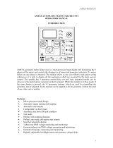
2 PERFORMANCE AND CHARACTERISTICS
HGM7110N:used for stand-alone automation, and it controls generator to start/stop by remote start
signal;
HGM7120N: Added Mains monitoring and Mains/Gens Automatic Transfer (AMF) function based
on HGM7110N, especially suitable for single unit automation system composed by one way
generator and one way Mains.
Main features are as below:
32-bit ARM SCM, high integration hardware, performance getting higher improved.
132x64 LCD with backlight, interface operation of optional languages (Chinese, English and other
languages), and languages can be selected in the field, which provides convenience for debugging
personnel commissioning.
Screen protection applies hard-screen acrylic material, with better wear-resisting and
scratch-resisting features.
Silicone panel and pushbuttons, strong adaptability in extreme high/low temperature environments.
RS485 communication port, can realize “three remote functions” (remote control, remote measuring
and remote communication) by MODBUS protocol.
Suitable for 3-phase 4-wire, 3-phase 3-wire, single phase 2-wire, and 2-phase 3-wire systems with
voltage 120/240V and frequency 50/60Hz;
Collects and shows 3-phase voltage and current, power parameter and frequency of generator or
mains.
Mains Generator
Line voltage (Uab, Ubc, and Uca) Line voltage (Uab, Ubc, and Uca)
Phase voltage (Ua, Ub, and Uc) Phase voltage (Ua, Ub, and Uc)
Frequency Hz Frequency Hz
Phase sequence Phase sequence
Load
Current Ia, Ib, Ic A (unit)
Each phase and total active power P kW (unit)
Reactive power Q kvar (unit)
Apparent power S kVA (unit)

HGM7100N GENSET CONTROLLER USER MANUAL
HGM7100N Genset Controller 2020-09-10 Version1.2 Page 5 of 47
Power factor PF
Accumulate total generator power W kWh, kVarh, kVAh (unit)
Output percentage with load %
For Mains, controller has over and under voltage, over and under frequency, loss of phase, and
phase sequence wrong functions; for generator, controller has over and under voltage, over and
under frequency, over current and over power, reverse power, loss of phase, phase sequence
wrong functions.
Precisely collect parameters about Engine.
Temp. (WT) °C/°F
Oil Pressure (OP) kPa/psi/Bar
Fuel Level (FL) %(unit)
Speed r/min (RPM)
Voltage of Battery V (unit)
Voltage of Charger V (unit)
Total running accumulation maximum 65535 hours can be recorded.
Start times accumulation maximum 65535 times can be recorded
Control protection function: realize automatic start/stop of the diesel gen-set, breaker close/open
(Auto Transfer Switch) control and perfect fault indication and protection functions etc.
With ETS (energize to stop), idle control, pre-heat control and rise/drop speed control functions,
which are all relay outputs.
Parameter setting function: allow users to modify and set parameters and at the same time
parameters can be stored in internal FLASH memory and won't get lost even in case of power
outage; most of them can be adjusted from front panel of the controller and all parameters ca be
adjusted via USB by PC, or via RS485 or ETHERNET port;
Multiple temperature, pressure, fuel level sensor curves can be used and custom sensor curves are
available.
Multiple crank disconnect conditions (speed, oil pressure, generator frequency) are optional.
Wide power supply range DC(8~35)V, suitabel for different starting battery voltage environments.
Event log, real-time clock, scheduled start & stop generator (can be set as start genset once a
day/week/month whether with load or not). Two gensets cycle start function.
Controller can record data up to 5 pieces include mains voltage, mains frequency, generator
voltage, generator frequency, current, temperature, oil pressure, fuel level, speed and etc. one
minute before shutdown fault.
It can be used for pumping unit, moreover, can be indicating instrument as well (only indicate and
no action for alarm and relay).
Maintenance function, maintenance time or maintenance time due can be user-defined (only
warning/trip shutdown/alarm shutdown).
Cycle start two gensets via RS485 or Internet access (running time of both main unit and standby
unit can be user defined)
Waterproof security level IP65 due to rubber seal installed between the controller enclosure and
panel foil.
Controller uses metal fixing clips.
Modular design, pluggable connection terminals and embedded installation way, and compact
structure with easy mounting.

HGM7100N GENSET CONTROLLER USER MANUAL
HGM7100N Genset Controller 2020-09-10 Version1.2 Page 6 of 47
3 SPECIFICATION OPERATION
Table 2 - Technical Parameters
Items
Contents
Operating Voltage
DC8.0V to DC35.0V, Continuous Power Supply.
Power Consumption
<4W (standby ≤2W)
Alternator Volt Input Range
3Phase 4Wire
3Phase 3Wire
Single Phase 2Wire
2Phase 3Wire
15V AC - 360 V AC (ph-N)
30V AC - 620 V AC (ph-ph)
15V AC - 360 V AC (ph-N)
15V AC - 360 V AC (ph-N)
Alternator Frequency
50 Hz/60Hz
Speed sensor voltage
1.0V to 24.0V (RMS)
Speed sensor Frequency
10,000 Hz (max.)
Starter Relay Output
16 A 28V DC at supply output
Fuel Relay Output
16 A 28VDC at supply output
Programmable Relay Output 1
7A 28V DC power supply output
Programmable Relay Output 2
8A 250V AC volt free output
Programmable Relay Output 3
16A 250V AC volt free output
Programmable Relay Output 4
16A 250V AC volt free output
Programmable Relay Output 5
7A 28V DC power supply output
Programmable Relay Output 6
7A 28V DC power supply output
Case Dimension
209mm x 166mm x 45mm
Panel Cutout
186mm x 141mm
CT Secondary Current
5A rated
Working Conditions
Temperature: (-25~+70)°C; Humidity: (20~93)%
Storage Condition
Temperature: (-25~+70)°C
Protection Level
IP65 Front panel
Insulating Intensity
Apply AC2.2kV voltage between high voltage terminal and low
voltage terminal and the leakage current is not more than 3mA
within 1min.
Weight
0.6kg

HGM7100N GENSET CONTROLLER USER MANUAL
HGM7100N Genset Controller 2020-09-10 Version1.2 Page 7 of 47
4 OPERATION
4.1 KEY FUNCTION
Table 3 - Key Function Descriptions
Icon
Function
Description
Stop/ Reset
Stop running generator in Auto/Manual mode;
In stop mode, reset alarms;
Pressing and holding the button for 3 seconds will test indicator
lights (lamp test);
During stopping process, press this button again to stop generator
immediately.
Start
Under manual mode, press this button and genset can be started;
Manual
Pressing this key will set the module into manual mode.
Auto
Pressing this key will set the module into auto mode.
C/O
Press this key to control breaker close or open under manual mode.
(only suit for HGM7120N)
Close
Press this key to control breaker close under manual mode.
(only suit for HGM7110N)
Open
Press this key to control breaker open under manual mode.
(only suit for HGM7110N)
Set/Confirm
Pressing this key will enter into Main Menu;
In setting parameter status, press this key to shift cursor or confirm
setting value.
Up/Increase
Scrolls the screen up; Shift the cursor up or increase the set value
in parameter setting menu.
Down/Decrease
Scrolls the screen down; Shift the cursor down or decrease the set
value in parameter setting menu.
Homepage/Return
Return to homepage in main interface; return to previous interface
in parameter setting screen; press for over 3s to reset trip alarms.
NOTE: press any key to mute alarms in main screen.

HGM7100N GENSET CONTROLLER USER MANUAL
HGM7100N Genset Controller 2020-09-10 Version1.2 Page 8 of 47
4.2 CONTROLLER PANEL
Fig. 1 - HGM7110N Front Panel Indication
Fig. 2 - HGM7120N Front Panel Indication
NOTE: Part of indicator lights illustration:
Table 4 - Alarm Indicator Description
Alarm Type
Alarm Indicators
Warning alarm
slowly flash (once per second)
Trip alarm
slowly flash (once per second)
Shutdown alarm
fast flash (5 times per second)

HGM7100N GENSET CONTROLLER USER MANUAL
HGM7100N Genset Controller 2020-09-10 Version1.2 Page 9 of 47
Trip and stop alarm
fast flash (5 times per second)
NOTE:
a) Status Indicators: after crank disconnect, light is always on before ETS; light is off for other periods.
b) Gen Normal Indicator: always on when generator is normal; flash when generating is abnormal; light is off when
there is no generating.
c) Mains Normal Indicator: always on when mains is normal; flash when mains is abnormal; light is off when there is
no Mains.
4.3 AUTO START/STOP OPERATION
4.3.1 ILLUSTRATION
Press , and its indicator is illuminated, which means genset enters Auto Start mode.
4.3.2 AUTO START SEQUENCE
a) HGM7120N: When Mains is abnormal (over and under voltage, over and under frequency, loss of
phase and phase sequence wrong), it enters into "mains abnormal delay” and status page of LCD
displays countdown time. When mains abnormal delay is over, it enters into “start delay”. Or when
remote start (onload) input is active, it enters into "start delay";
b) HGM7110N: It enters into “start delay” as soon as “Remote Start on Load” input is active.
c) Start Delay countdown is shown on status page of LCD.
d) When start delay is over, preheat relay outputs (if configured), “preheat start
delay XX s” is shown on status page of LCD.
e) When preheat delay is over, fuel relay outputs for1s and then start relay outputs; if engine crank fails
during “cranking time”, the fuel relay and start relay are deactivated and enter into “crank rest time” to
wait for next crank.
f) If engine crank fails within setting times, controller will initiate fail to start shutdown signals and fail to
start message appears on LCD display at the same time.
g) In case of successful crank attempt, “safety on timer” starts. During this period, low oil pressure, high
water temperature, under speed, and charge failure alarms are disabled. As soon as this delay is
over, “start idle delay” is initiated (if configured).
h) During “start idle delay”, under speed, under frequency, under voltage alarms are inhibited. When
this delay is over, “warming up delay” starts (if configured).
i) When “warming up delay” is over, if generating state is normal, its indicator will be illuminated. If
voltage and frequency has reached on-load requirements, then the closing relay will be energized,
generator will accept load, generator power indicator will turn on, and generator will enter Normal
Running state; if voltage and frequency are abnormal, the controller will initiate shutdown alarm
(shutdown alarm will be displayed on LCD alarm page).
NOTE: when remote start (off-load) signal input is active, the auto start sequence is the same as above. Only in
item i), generator closing relay will not output, and genset is off-load.
4.3.3 AUTO STOP SEQUENCE
a) HGM7120N: when Mains return to normal during gen-set running, controller enters into Mains
voltage “Normal delay”. After Mains normal status confirmed, Mains status indicator is illuminated
and “stop delay” initiated. Or when remote start input is inactive, "stop delay" starts;
b) HGM7110N: generator enters into “stop delay” as soon as “Remote Start” input is inactive.

HGM7100N GENSET CONTROLLER USER MANUAL
HGM7100N Genset Controller 2020-09-10 Version1.2 Page 10 of 47
c) When stop delay is over, close generator relay is un-energized; generator enters into “cooling down
time”. After “switch transfer delay”, Mains close relay is energized. Mains is on load and generator
indicator extinguished while mains indicator lights on.
d) Idle relay is energized as soon as entering “stop idle delay” (if configured).
e) If enters “ETS hold delay”, ETS relay is energized. Fuel relay is deactivated and whether stop or not
is auto judged.
f) Then enters gen-set “wait for stop time”, and whether stop or not is auto judged.
g) Enters “after stop time” after gen-set stopped completely. If genset failed to stop, controller will
initiate fail to stop warning (if gen-set stopped after the alarms, it will enter into “after stop time” and
fail to stop alarms will be eliminated automatically).
h) Enters standby status as soon as “after stop time” is over.
4.4 MANUAL START/STOP OPERATION
a) HGM7120N: Manual mode is selected by pressing the button, and manual mode indicator is
illuminated; In this mode, press button to start the genset, it can automatically judge crank
disconnect and accelerate to high speed running automatically. If high temperature, low oil pressure,
over speed and abnormal voltage occur during diesel genset running, controller can effectively protect
genset to stop (for detailed procedures please refer to No. d~i of 4.3.2 Auto start sequence). Under
Manual Mode, load breaker won’t transfer automatically and C/O key should be pushed
manually to enter into the C/O interface.
b) HGM7110N: Manual mode is selected by pressing the button and manual mode indicator is
illuminated; Then press button to start the generator, it can automatically judge crank
disconnect and accelerate to high speed running. If high temperature, low oil pressure, over speed
and abnormal voltage occur during genset running, controller can effectively protect genset to stop
(for detailed procedures please refer to No. d~i of 4.3.2 Auto start sequence). After genset high speed
normal running, press the key manually to close generator and generator is on-load.
c) Manual stop: pressing key can stop the running genset. (For detailed procedures please
refer to No. c~h of 4.3.3 Auto stop sequence.)
4.5 EMERGENCY START
Simultaneously pressing and in manual mode will force generator to crank. Successful
start will not be judged according to crank disconnect conditions, operator will have to crank the starter
motor manually; when operator decides that the engine has started, he/she should release the button
and start output will be deactivated, safety on delay will be initiated.

HGM7100N GENSET CONTROLLER USER MANUAL
HGM7100N Genset Controller 2020-09-10 Version1.2 Page 11 of 47
5 BREAKER CONTROL PROCESS OF GENSET CONTROLLER
5.1 HGM7120N BREAKER CONTROL PROCESS
5.1.1 MANUAL SWITCHING PROCESS
When controller is in manual mode, switch control process executes manual transfer process.
Operators control ATS load transfer by close/open key.
If open detection is disabled, press Gen close/open key ; if Gen takes the load, breaker open
outputs; if load is disconnected, then Gen closes; If Mains takes the load, then Mains breaker openes;
when open delay is over, Gen closes; Press Mains close/open , if Mains takes the load, then
breaker open outputs; if load is disconnected, then Mains closes; If Gen takes, when open delay is
over, Mains closes.
If open detection is enabled, for Mains onload transferring to Gen onload, first press Mains open
key , after open delay, press Gen close key , Gen close (press Gen close key directly, no
action). For Gen onload transferring to Mains onload, same procedure as above.
5.1.2 AUTO SWITCHING PROCESS
When controller is in auto or stop mode, switch control procedure executes auto transfer process.
a) If input port configured as close status auxiliary input
• If breaker open detection is enabled, for Mains onload transferring to Gen onload, after
open delay, and transfer interval delay, at the time when breaker open outputs, transfer
failure starts to detect; when detection time is due, if open fails, then Gen doesn't close,
otherwise Gen closes, at the time of Gen closes, transfer fail starts to detect; when
detection time is due, if close fails, then it waits for Gen close. If transfer failure warning is
enabled, close/open failure will issue warning signal. For Gen onload transferring Mains
onload, the same procedure as above.
• If breaker open detection is disabled, for Mains onload transferring to Gen oload, after
open delay and transfer interval delay, Gen breaker closes, at the time of Gen closes,
transfer failure starts to detect; when detection time is due, if close fails, then wait for Gen
closes. If transfer failure warning is enabled, warning signal is issued.
b) If input port not configured as close status auxiliary input
For Mains onload transferring to Gen onload, after open delay and transfer interval delay, Gen
closes; For Gen onload transferring to Mains onload, the same procedure is as above.
5.2 HGM7110N BREAKER CONTROL PROCESS
5.2.1 MANUAL SWITCHING PROCESS
When controller is in manual mode, switch control process executes manual control process.
Operators control switch's close/open by close/open key.
Press Gen close key , if Gen is not onload, then Gen close outputs; Press Gen open key ,
if Gen is onload, then Gen open outputs.

HGM7100N GENSET CONTROLLER USER MANUAL
HGM7100N Genset Controller 2020-09-10 Version1.2 Page 12 of 47
5.2.2 AUTO SWITCHING PROCESS
When controller is in auto mode, switch control process executes auto control process.
a) If input port configured as close status auxiliary input
• If breaker open detection is enabled, for Gen onload transferring to Gen offload, after open
delay, at the time of open output, transfer failure starts to detect; when detection time is due, if
open fails, then it waits for open, otherwise, open is completed. For Gen offload transferring
to Gen onload, after close delay, at the time of close output, transfer failure starts to detect;
when detection time is due, if close fails, then it waits for close, otherwise, close is completed.
• If transfer failure warning is enabled, then it will issue warning signals both for close/open.
• If open detection is not enabled, for Gen onload transferring to Gen offload, after open delay,
open is completed. For Gen offload transferring to Gen onload, after close delay, at the time
of close output, transfer failure starts to detect; when detection time is up, if close fails, then it
waits for close, otherwise, close is completed. If transfer failure warning is enabled, it will
issue warning signal for close failure.
b) If input port not configured as close status auxiliary input
For Gen offload transferring to Gen onload, Gen close outputs. For Gen onload transferring to
Gen offload, Gen open outputs.
NOTES:
1) If ATS without neutral position is used, breakers open detection should be disabled.
2) If ATS with neutral position is used, breakers open detection can be enabled or disabled (please configured the
breaker open output if enabled).
3) If AC contactors are used, breakers open detection enable will be recommended.

HGM7100N GENSET CONTROLLER USER MANUAL
HGM7100N Genset Controller 2020-09-10 Version1.2 Page 13 of 47
6 PROTECTION
6.1 WARNINGS
When controllers detect the warning signals, it only issues warnings, not stops the genset.
Table 5 - Warning Alarms Types
No.
Type
Description
1
Gen. Over Speed
When the controller detects that the speed of genset exceeds the
pre-set value, it will initiate a warning alarm.
2
Gen. Under Speed
When the controller detects that the speed of genset falls below the
pre-set value, it will initiate a warning alarm.
3
Loss of Speed Signal
When the controller detects that the speed of genset is zero and action
select “Warning”, it will initiate a warning alarm.
4
Gen. Over Frequency
When the controller detects that the frequency of genset exceeds the
pre-set value, it will initiate a warning alarm.
5
Gen. Under Frequency
When the controller detects that the frequency of genset falls below
the pre-set value, it will initiate a warning alarm.
6
Gen. Over Voltage
When the controller detects that the voltage of genset exceeds the
pre-set value, it will initiate a warning alarm.
7
Gen. Under Voltage
When the controller detects that the voltage of genset falls below the
pre-set value, it will initiate a warning alarm.
8
Gen. Over Current
When the controller detects that the current of genset exceeds the
pre-set value, it will initiate a warning alarm.
9
Failed to Stop
If engine does not stop completely when fail to stop delay expired, it
will initiate a warning alarm.
10
Charge Alt Fail
When the controller detects that the voltage of charger falls below the
pre-set value, it will initiate a warning alarm.
11
Battery High Voltage
When the controller detects that the battery voltage of genset exceeds
the pre-set value, it will initiate a warning alarm.
12
Battery Low Voltage
When the controller detects that the battery voltage of genset falls
below the pre-set value, it will initiate a warning alarm.
13
Maintenance Time Due
When maintenance countdown is zero and action select “Warning”, it
will initiate a warning alarm.
14
Reverse Power
When controller detects that the reverse power value (power is
negative) of genset exceeds the pre-set value, and action type select
“Warning”, it will initiate a warning alarm.
15
Over Power
When controller detects that the power value (power is positive) of
genset exceeds the pre-set value, and action type select “Warning”, it
will initiate a warning alarm.
16
Gen. Loss of Phase
When controller detects that the phase of generator is loss, it will
initiate a warning alarm.
17
Gen. Reverse Phase
When controller detects that the phase sequence of generator is
wrong, it will initiate a warning alarm.

HGM7100N GENSET CONTROLLER USER MANUAL
HGM7100N Genset Controller 2020-09-10 Version1.2 Page 14 of 47
No.
Type
Description
18
Breaker Switch Fail
When controller detects that the breaker is fail to close/open (when the
warning is enabled), it will initiate a warning alarm.
19
Temp. Sensor Open
Circuit
When controller detects that the temperature sensor is open circuit and
action select “Warning”, it will initiate a warning alarm.
20
High Temp. Warning
When controller detects that the temperature is higher than the pre-set
value, it will initiate a warning alarm.
21
Low Temp. Warning
When controller detects that the temperature is lower than the pre-set
value, it will initiate a warning alarm.
22
Oil Pressure Sensor
Open Circuit
When controller detects that sensor is open circuit, and action type
select “Warning”, it will initiate a warning alarm.
23
Low Oil Pressure
Warning
When controller detects that the oil pressure value falls below the
pre-set value, it will initiate a warning alarm.
24
Level Sensor Open
Circuit
When controller detects that sensor is open circuit, and action type
select “Warning”, it will initiate a warning alarm.
25
Low Level Warning
When controller detects that the liquid level value falls below the
pre-set value, it will initiate a warning alarm.
26
Config. Sensor 1 Open
Circuit
When controller detects that sensor is open circuit, and action type is
select “Warning”, it will initiate a warning alarm.
27
Config. Sensor 1 High
When controller detects that the sensor value exceeds the pre-set
upper limit warning value, it will initiate a warning alarm.
28
Config. Sensor 1 Low
When controller detects that the sensor value falls below the pre-set
lower limit warning value, it will initiate a warning alarm.
29
Config. Sensor 2 Open
Circuit
When controller detects that sensor is open circuit, and action type is
select “Warning”, it will initiate a warning alarm.
30
Config. Sensor 2 High
When controller detects that the sensor value exceeds the pre-set
upper limit warning value, it will initiate a warning alarm.
31
Config. Sensor 2 Low
When controller detects that the sensor value falls below the pre-set
lower limit warning value, it will initiate a warning alarm.
32
Input Warning
When digital input port configured as “Warning”, and it is active,
controller will initiate a warning alarm.
33
Cycle Start
Communication Fail
Warning
When two gensets, which during in cycle start status, fail to
communicate, controller will initiate a warning alarm.

HGM7100N GENSET CONTROLLER USER MANUAL
HGM7100N Genset Controller 2020-09-10 Version1.2 Page 15 of 47
6.2 SHUTDOWN ALARM
When controller detects shutdown alarms, it immediately opens the breaker and stop the genset, at the
same time it displays alarm type.
Table 6 - Shutdown Alarms
No.
Type
Description
1
Emergency Stop
When controller detects emergency stop signals, it will send stop
signals.
2
Over Speed
When controller detects the speed value is higher than the set value,
it will send stop signals.
3
Under Speed
When controller detects the speed value is lower than the set value, it
will send stop signals.
4
Loss of Speed Signal
When controller detects speed value equals to 0, and action select
“Shutdown”, it will send stop signals.
5
Gen Over Frequency
When controller detects the frequency value is higher than the set
value, it will send stop signals.
6
Gen Under Frequency
When controller detects the frequency value is lower than the set
value, it will send stop signals.
7
Gen. Over Voltage
When controller detects the voltage value of genset is higher than the
set value, it will send stop signals.
8
Gen. Under Voltage
When controller detects the voltage value of genset is lower than the
set value, it will send stop signals.
9
Failed to Start
If genset start failure within setting of start times, controller will send
stop signals.
10
Gen. Over Current
When controller detects the current value is higher than the set value
and action select “Shutdown”, it will send stop signals.
11
Maintenance Time Due
When maintenance time countdown equals to 0, and action select
“Shutdown”, it will send stop signals.
12
Reverse Power
Shutdown
When controller detects that the reverse power value (power is
negative) of genset exceeds the pre-set value, and action type select
“Shutdown”, it will send stop signals.
13
Over Power Shutdown
When controller detects that the power value (power is positive) of
generator-set exceeds the pre-set value, and action type select
“Shutdown”, it will send stop signals.
14
Temp. Sensor Open
Circuit
When controller detects sensor is open circuit, and the action select
“shutdown”, it will send stop signals.
15
High Temp. Shutdown
When controller detects temperature of water/cylinder is higher than
the set value, it will send stop signals.
16
Oil Pressure Sensor
Open Circuit
When controller detects sensor is open circuit, and the action select
“shutdown”, it will send stop signals.

HGM7100N GENSET CONTROLLER USER MANUAL
HGM7100N Genset Controller 2020-09-10 Version1.2 Page 16 of 47
No.
Type
Description
17
Low Oil Pressure
Shutdown
When controller detects oil pressure is lower than the set value, it will
send stop signals.
18
Level Sensor Open
Circuit
When controller detects sensor is open circuit, and the action select
“shutdown”, it will send stop signals.
19
Low Level Shutdown
When controller detects liquid level is lower than the set value, it will
send stop signals.
20
Config. Sensor 1 Open
Circuit
When controller detects that sensor is open circuit, and action type is
select “Shutdown”, it will send stop signals.
21
Config. Sensor 1 High
When controller detects that the sensor value exceeds the pre-set
upper limit shutdown value, it will send stop signals.
22
Config. Sensor 1 Low
When controller detects that the sensor value falls below the pre-set
lower limit shutdown value, it will send stop signals.
23
Config. Sensor 2 Open
Circuit
When controller detects that sensor is open circuit, and action type is
select “Shutdown”, it will send stop signals.
24
Config. Sensor 2 High
When controller detects that the sensor value exceeds the pre-set
upper limit shutdown value, it will send stop signals.
25
Config. Sensor 2 Low
When controller detects that the sensor value falls below the pre-set
lower limit shutdown value, it will send stop signals.
26
Input Alarm Shutdown
When digital input port configured as “Shutdown”, and it is active,
controller will send stop signals.

HGM7100N GENSET CONTROLLER USER MANUAL
HGM7100N Genset Controller 2020-09-10 Version1.2 Page 17 of 47
6.3 TRIP AND STOP ALARM
When controller detects trip and stop alarms, it will immediately disconnect the generator closing
signals and engine will shut down after high-speed cooling.
Table 7 - Trip and Stop Alarms
No.
Type
Description
1
Over Current
When controller detects the current value of genset is higher than the
set value and action select “Trip and Stop”, it will send trip and stop
signals.
2
Maintenance Time
Due
When maintenance time countdown equals to 0, and action select
“Trip and Stop”, it will send trip stop signals.
3
Reverse Power
When controller detects that the reverse power value (power is
negative) of genset exceeds the pre-set value, and action type select
“Trip and Stop”, it will send trip and stop signals.
4
Over Power
When controller detects that the power value (power is positive) of
genset exceeds the pre-set value, and action type select “Trip and
Stop”, it will send trip and stop signals.
5
Input Trip and Stop
When input port configured as “Trip and Stop”, and it is active,
controller will send trip and stop signals.
6.4 TRIP ALARM
When controller detects trip alarms, it will immediately disconnects the generator closing signals and
genset does not shut down.
Table 8 - Trip Alarms
No.
Type
Description
1
Over Current
When controller detects the current value of genset is higher than the set
value and action select “Trip”, it will send trip signals.
2
Reverse Power
When controller detects that the reverse power value (power is negative)
of genset exceeds the pre-set value, and action type select “Trip”, it will
send trip signals.
3
Over Power
When controller detects that the power value (power is positive) of genset
exceeds the pre-set value, and action type select “Trip”, it will send trip
signals.
4
Input Trip
When input port configured as “Trip”, and it is active, controller will send
trip signals.

HGM7100N GENSET CONTROLLER USER MANUAL
HGM7100N Genset Controller 2020-09-10 Version1.2 Page 18 of 47
7 WIRINGS CONNECTION
Compared with HGM7120N, HGM7110N is missing one mains voltage three-phase input terminal.
HGM7120N controller back panel is as follows:
Fig. 3 - HGM7120N Back Panel
Table 9 - Terminal Wiring Connection
No.
Function
Cable Size
Remarks
1
B-
2.5mm2
Connected with negative of starter battery
2
B+
2.5mm2
Connected with positive of starter battery. If wire length
is over 30m, better to double wires in parallel. Max. 20A
fuse is recommended.
3
Emergency Stop
2.5mm2
Connect emergency stop button with B+.
4
Fuel (16A)
1.5mm2
B+ is supplied by No.3 terminal, rated 16A.
5
Crank (16A)
1.5mm2
B+ is supplied by No.3 terminal, rated 16A.
Connect with starting coil of starter.
6
Aux. Output 1(7A)
1.5mm2
B+ is supplied by No.2 terminal, rated 7A.
7
Aux. Output 2(8A 250VAC)
1.5 mm2
Normally close output,
rated 8A.
Details see Table 11
8
Relay common port

HGM7100N GENSET CONTROLLER USER MANUAL
HGM7100N Genset Controller 2020-09-10 Version1.2 Page 19 of 47
No.
Function
Cable Size
Remarks
9
Normally open output,
rated 8A.
10
Aux. Output 3(16A 250VAC)
2.5 mm2
Relay normally open volt
free contact, rated 16A,
volt free contact output.
11
12
Aux. Output 4(16A 250VAC)
2.5 mm2
13
14
Charger(D+)
1.0mm2
Connected with charger starter’s D+ (WL) terminals.
Being hang up If there is no this terminal.
15
Aux. Output 5(7A)
1.5 mm2
B+ is supplied by No.2
terminal, rated 7A
Details see Table 11
16
Aux. Output 6(7A)
1.5 mm2
17
Speed Sensor Input
Connect with speed sensor, shielded wire is recommended.
18
Speed sensor input, battery
negative electrode has been
connected to the inside of
controller.
19
Engine Temp.
Connected with temperature sensor
Details to see table 13
20
Oil Pressure
Connected with pressure sensor
21
Fuel Level
Connected with fuel level sensor
22
Aux. Input 1
1.0mm2
Ground connected is active (B-)
Details to see table 12
23
Aux. Input 2
1.0mm2
Ground connected is active (B-)
24
Aux. Input 3
1.0mm2
Ground connected is active (B-)
25
Aux. Input 4
1.0mm2
Ground connected is active (B-)
26
Aux. Input 5
1.0mm2
Ground connected is active (B-)
27
Sensor Common Port
Sensor common port, battery negative electrode has been
connected to the inside of controller.
28
Aux. Input 6
1.0mm2
Ground connected is active (B-)
Details to see table 12
29
Aux. Input 7
1.0mm2
Ground connected is active (B-)
30
Configurable Sensor 1
Connected with temp/pressure/fuel level
sensor.
Details to see table 13
31
Configurable Sensor 2
32
CT A-phase Monitoring Input
1.5mm2
Outside connected to secondary coil of CT (5A rated).
33
CT B-phase Monitoring Input
1.5mm2
Outside connected to secondary coil of CT (5A rated).
34
CT C-phase Monitoring
Input
1.5mm2
Outside connected to secondary coil of CT (5A rated).
35
CT Common Port
1.5mm2
Details to see the following installation description.
36
Gen U-phase Voltage
Monitoring Input
1.5mm2
Connected to U-phase output of genset (2A fuse
recommended).
37
Gen V-phase Voltage
Monitoring Input
1.0mm2
Connected to V-phase output of genset (2A fuse
recommended).

HGM7100N GENSET CONTROLLER USER MANUAL
HGM7100N Genset Controller 2020-09-10 Version1.2 Page 20 of 47
No.
Function
Cable Size
Remarks
38
Gen W-phase Voltage
Monitoring Input
1.0mm2
Connected to W-phase output of genset (2A fuse
recommended).
39
Gen N2-line Input
1.0mm2
Connected to N-line output of genset.
40
Mains R-phase Voltage
Monitoring Input
1.0mm2
Connected to R-phase of mains (2A fuse recommended).
(HGM7110N without)
41
Mains S-phase voltage
monitoring input
1.0mm2
Connected to S-phase of mains (2A fuse recommended).
(HGM7110N without)
42
Mains T-phase voltage
monitoring input
1.0mm2
Connected to T-phase of mains (2A fuse recommended).
(HGM7110N without)
43
Mains line N1 Input
1.0mm2
Connected to N-line of mains. (HGM7110N without)
44
RS485 Common Ground
0.5mm2
120Ω shielded wire is recommended with single end
ground.
45
RS485-
0.5mm2
46
RS485+
0.5mm2
47
VOUT(+5V)
0.5mm2
Output DC +5V.
NOTE: USB ports in controller rear panel are programmable parameter ports, user can directly configure the
controller via PC.
NOTE: ETHERNET port in controller rear panel is network monitoring port, user can directly monitor the controller
via PC.
/