Page is loading ...

HC Switch FM
(MT:02759)
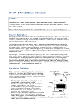
This Z-Wave module is used for switching on or off the
electrical device (e.g. light or fan). The module operates on
868,4 MHz. The module can be controlled either through
Z-wave network or through the wall switch. The module is
designed to be mounted inside a “flush mounting box”,
hidden behind a traditional wall switch. Module measures
power consumption of electrical device and supports
connection of digital temperature sensor. It is designed to
act as repeater in order to improve range and stability of
Z-wave network.
Supported switches
Module supports mono-stable switches (push button)
and bi-stable switches. The module is factory set to
operate with bi-stable switches.
Installation
To prevent electrical shock and/or equipment damage,
disconnect electrical power at the main fuse or circuit
breaker before installation or any servicing.
Make sure, that no voltage is present in the
installation.
Prevent the disconnecting device from being switched
on accidentally.
Connect the module according to electrical diagram.
Locate the antenna far from metal elements (as far as
possible).
Do not shorten the antenna.
Danger of electrocution!
Module installation requires a great degree of skill and
may be performed only by a qualified and licensed
electrician.
Even when the module is turned off, voltage may be
present on its terminals.
Note!
Do not connect the module to loads exceeding
recommended values. Connect the module only in
accordance to the below diagrams. Improper connections
may be dangerous.
Electrical installation must be protected by directly
associated over current protection fuse 10A, gG or
Time lag T, rated breaking capacity 1500A (ESKA
522.727) must be used according to wiring diagram to
achieve appropriate overload protection of the module.
The fuse must be installed in fuse holder: e.g Adels
contact 503 Si/ 1DS.
Electrical diagram 230VAC
Notes for the diagram:
N
Neutral lead
L
Live lead
Q
Output for electrical device
I3
Input for switch /push button or sensor
I2
Input for switch /push button or sensor
I1
Input for switch /push button
TS
Terminal for digital temperature sensor (only for HC
Switch relay module compatible digital temperature
sensor, which must be ordered separately).
Wago 221-413 splicing connectors for L and N connection
must be used.
Electrical diagram 24VDC
Notes for the diagram:
N
+ VDC
L
- VDC
Q
Output for electrical device
I3
Input for switch /push button or sensor
I2
Input for switch /push button or sensor
I1
Input for switch /push button
TS
Terminal for digital temperature sensor (only for
Flush 1 relay module compatible digital temperature
sensor, which must be ordered separately).
WARNING: Service button S must NOT be used when
module is connected to 110-230V power supply.
Durability of the module depends on applied load. For
resistive load (light bulbs,..) and 10A current consumption
of each individual electrical device, the durability exceeds
100.000 switches of each individual electrical device.
Package contents
Devolo HC switch relay module
Module Inclusion (Adding to Z-wave network)
Connect module to power supply (with
temperature sensor connected - if purchased*),
enable add/remove mode on main controller
auto-inclusion (works for about 2 minutes after
connected to power supply) or
press push button I1 three times within 5s (3 times
change switch state within 5 seconds) or
press service button S (only applicable for 24 V SELV
supply voltage) for more than 2 second.
NOTE 1: For auto-inclusion procedure, first set main
controller into inclusion mode and then connect module to
power supply.
NOTE 2: When connecting temperature sensor to module
that has already been included, you have to exclude
module first. Switch off power supply, connect the sensor
and re-include the module.
Module Exclusion/Reset (Removing from
Z-Wave network)
Connect module to power supply
bring module within maximum 1 meter (3 feet) of the
main controller,
enable add/remove mode on main controller
press push button I1 five times within 5s (5 times
change switch state within 5 seconds) in the first 60
seconds after the module is connected to the power
supply or
press service button S (only applicable for 24 V SELV
supply voltage) for more than 6 second.
By this function all parameters of the module are set to
default values and own ID is deleted.
Please use this procedure only when the network primary
controller is missing or otherwise inoperable.
If push button I1 is pressed three times within 5s (or service
button S is pressed more than 2 and less than 6 seconds)
module is excluded, but configuration parameters are not
set to default values.
NOTE: If the module is included with parameters 100 or
101 with values different to default and module reset is
done, wait at least 30s before next inclusion.
Associations
Association enable the HC Switch relay module to transfer
commands inside Z-Wave network directly (without main
controller) to other Z-Wave modules.
Associated Groups:
Root device: S Service button (used to add or
remove module from the Z-Wave
network in case of 24 V SELV power
supply).
Group 1: Lifeline group (reserved for communication with
the main controller), 1 node allowed.
Group 2: basic on/off (triggered at change of the output Q
state and reflecting its state) up to 16 nodes.
Group 3: basic on/off (triggered at change of the input I2
state and reflecting its state) up to 16 nodes.
Group 4: Notification report (triggered at change of the
input I2 state and reflecting its state) up to 16 nodes.
Group 5: Binary sensor (triggered at change of the input I2
state and reflecting its state) up to 16 nodes.
Group 6: basic on/off (triggered at change of the input I3
state and reflecting its state) up to 16 nodes.
Group 7: notification report (triggered at change of the input
I3 state and reflecting its state) up to 16 nodes.
Group 8: binary sensor report (triggered at change of the
input I3 state and reflecting its state) up to 16 nodes.
Group 9: multilevel sensor report (triggered at change of
temperature sensor) up to 16 nodes.
Endpoint 1:
Group 1: Lifeline group, 0 nodes allowed.
Group 2: basic on/off (triggered at change of the output
state and reflecting its state) up to 16 nodes.
Endpoint 2:
Group 1: Lifeline group, 0 nodes allowed.
Group 2: basic on/off (triggered at change of the input I2
state and reflecting its state) up to 16 nodes.
Group 3: Notification Report (triggered at change of the
input I2 state and reflecting its state) up to 16 nodes.
Group 4: Binary Sensor Report (triggered at change of the
input I2 state and reflecting its state) up to 16 nodes.
Endpoint 3:
Group 1: Lifeline group, 0 nodes allowed.
Group 2: basic on/off (triggered at change of the input I3,
state and reflecting its state) up to 16 nodes.
Group 3: Notification Report (triggered at change of the
input I3 state and reflecting its state) up to 16 nodes.
Group 4: Binary Sensor Report (triggered at change of the
input I3 state and reflecting its state) up to 16 nodes.
End point 4:
Group 1: Lifeline group, 0 nodes allowed.
Group 2: multilevel sensor report (triggered at change of
temperature sensor) up to 16 nodes.
Configuration parameters
Parameter no. 1 – Input 1 switch type
Available config. parameters (data type is 1 Byte DEC):
default value 1
0 - mono-stable switch type (push button)
1 - bi-stable switch type
Parameter no. 2 – Input 2 contact type
Available config.parameters (data type is 1 Byte DEC):
default value 0
0 - NO (normally open) input type
1 - NC (normally close) input type
Parameter no. 3 – Input 3 contact type
Available config.parameters (data type is 1 Byte DEC):
default value 0
0 - NO (normally open) input type
1 - NC (normally close) input type
Parameter no. 10 - Activate / deactivate functions ALL
ON/ALL OFF
Available config.parameters (data type is 2 Byte DEC):
default value 255
255 - ALL ON active, ALL OFF active
0 - ALL ON is not active ALL OFF is not active
1 - ALL ON is not active ALL OFF active
2 - ALL ON active ALL OFF is not active
HC Switch relay module responds to commands ALL ON /
ALL OFF that may be sent by the main controller or by
other controller belonging to the system.
Parameter no. 11 - Automatic turning off output after
set time
When relay is ON it goes automatically OFF after time
defined by this parameter. Timer is reset to zero each time
the module receive ON command regardless from where it
comes (push button, associated module, controller,..).
Available configuration parameters (data type is 2 Byte
DEC):
default value 0
0 - Auto OFF disabled
1 - 32535 = 1second (0,01s) - 32535 seconds
(325,35s) Auto OFF enabled with define time, step is
1s or 10ms according to parameter nr.15.
Parameter no. 12 - Automatic turning on output after
set time
When relay is OFF it goes automatically ON after time
defined by this parameter. Timer is reset to zero each time
the module receive OFF command regardless from where
it comes (push button, associated module, controller,..).
Available configuration parameters (data type is 2 Byte
DEC):
default value 0
0 - Auto ON disabled
1 - 32535 = 1second (0,01s) - 32536 seconds
(325,35s) Auto ON enabled with define time, step is
1s or 10ms according to parameter nr.15.
Parameter no. 15 - Automatic turning off / on seconds
or milliseconds selection
Available config.parameters (data type is 1 Byte DEC):
default value 0
0 - seconds selected
1 - milliseconds selected
NOTE: Parameter is the same for turning OFF or ON.
Parameter no. 30 - Saving the state of the relay after a
power failure
Available config.parameters (data type is 1 Byte DEC):
default value 0
0 – HC Switch relay module saves its state before
power failure (it returns to the last position saved
before a power failure)
1 – HC Switch relay module does not save the
state after a power failure, it returns to "off" position.

Parameter no. 40 – Power reporting in Watts on power
change
Set value means percentage, set value from 0 – 100 = 0% -
100%. Available configuration parameters (data type is 1
Byte DEC):
default value 10 = 10%
0 - reporting disabled
1 - 100 = 1% - 100% reporting enabled
Power report is send (push) only when actual power
in Watts in real time changes for more than set
percentage comparing to previous actual power in
Watts, step is 1%. When using low power loads, It is
recommended to set parameter no. 40 to a higher
value (e.g. 50%).
NOTE: if power changed is less than 1W, the report is not
send (pushed), independent of percentage set.
Parameter no. 42 – Power reporting in Watts by time
interval
Set value means time interval (0 – 32535) in seconds,
when power report is send. Available configuration
parameters (data type is 2 Byte DEC):
default value 0 = 0s
0 - reporting disabled
30 - 32535 = 30second - 32535 seconds.
Reporting enabled. Power report is send with time
interval set by entered value.
Parameter no. 63 – Output Switch selection
Set value means the type of the device that is connected to
the output. The device type can be normally open (NO) or
normally close (NC). Available configuration parameters
(data type is 1 Byte DEC):
default value 0
0 - When system is turned off the output is 0V (NC).
1 - When system is turned off the output is 230V or
24V (NO).
Parameter no. 100 – Enable / Disable Endpoints I2 or
select Notification Type and Event
Enabling I2 means that Endpoint (I2) will be present on UI.
Disabling it will result in hiding the endpoint according to
the parameter set value. Additionally, a Notification Type
and Event can be selected for the endpoint. Available
configuration parameters (data type is 1 Byte DEC):
Endpoint device type selection:
- notification sensor (1 - 6):
GENERIC_TYPE_SENSOR_NOTIFICATION,
SPECIFIC_TYPE_NOTIFICATION_SENSOR
default value 1
1 - Home Security; Motion Detection, unknown loc.
2 - Carbon Monoxide; Carbon Monoxide detected,
unknown location.
3 – Carbon Dioxide; Carbon Dioxide detected,
unknown location.
4 - Water Alarm; Water Leak detected, unknown lo.
5 - Heat Alarm; Overheat detected, unknown loc.
6 - Smoke Alarm; Smoke detected, unknown loc.
0 - Endpoint, I2 disabled
NOTE1: After parameter change, first exclude module
(without setting parameters to default value) then wait at
least 30s and then re include the module!
Parameter no. 101 – Enable / Disable Endpoints I3 or
select Notification Type and Event
Enabling I3 means that Endpoint (I3) will be present on UI.
Disabling it will result in hiding the endpoint according to
the parameter set value. Additionally, a Notification Type
and Event can be selected for the endpoint. Available
configuration parameters (data type is 1 Byte DEC):
Endpoint device type selection:
- notification sensor (1 - 6):
GENERIC_TYPE_SENSOR_NOTIFICATION,
SPECIFIC_TYPE_NOTIFICATION_SENSOR
default value 1
1 - Home Security; Motion Detection, unknown loc.
2 - Carbon Monoxide; Carbon Monoxide detected,
unknown location.
3 - Carbon Dioxide; Carbon Dioxide detected,
unknown location.
4 - Water Alarm; Water Leak detected, unknown lo.
5 - Heat Alarm; Overheat detected, unknown loc.
6 - Smoke Alarm; Smoke detected, unknown loc.
0 - Endpoint, I3 disabled
NOTE1: After parameter change, first exclude module
(without setting parameters to default value) then wait at
least 30s and then re include the module!
Parameter no. 110 – Temperature sensor offset
settings
Set value is added or subtracted to actual measured value
by sensor. Available configuration parameters (data type is
2 Byte DEC):
default value 32536
32536 - offset is 0.0C
From 1 to 100 - value from 0.1°C to 10.0°C is added
to actual measured temperature.
From 1001 to 1100 - value from -0.1 °C to -10.0 °C is
subtracted to actual measured temperature.
Parameter no. 120 –Temperature sensor reporting
If digital temperature sensor is connected, module reports
measured temperature on temperature change defined by
this parameter. Available configuration parameters (data
type is 1 Byte DEC):
default value 5 = 0,5°C
0 - Reporting disabled
1- 127 = 0,1°C – 12,7°C, step is 0,1°C
Technical Specifications
Power supply
110 - 230 VAC ±10%
50/60Hz, (24-30VDC)
Rated load current of AC
output (resistive load)*
1 X 10A / 230VAC
Rated load current of DC
output (resistive load)
1 X 10A / 30VDC
Output circuit power of AC
output (resistive load)
2300W (230VAC)
Output circuit power of DC
output (resistive load)
240W (24VDC)
Power measurement
accuracy
P=5-50W, +/-3W
P>50W, +/-3%
Digital temp. sensor range
(must be ordered separately)
-50 ~ +125°C
Operation temperature
-10 ~ +40°C
Distance
up to 30 m indoors
Dimensions (WxHxD)
(package)
41,8x36,8x15,4mm
(79x52x22mm)
Weight (Brutto with package)
28g (34g)
Electricity consumption
0,4W
For installation in boxes
Ø ≥ 60mm or 2M,
depth≥ 60mm
Switching
Relay
* In case of load other than resistive, pay attention to the
value of cos φ and if necessary apply load lower than the
rated load. Max current for cos φ=0,4 is 3A at 250VAC, 3A
at 24VDC L/R=7ms.
Max Power Limit is automatically set by a software. If max
power is exceeded for more than 5 seconds, the output is
turned off up to next restart of the module. When overload
occurred, Event “Over-load detected” is sent to the
gateway (from Root or EndPoint1).
HC Switch relay module supports both, the secure and
unsecure inclusion, which is automatically selected during
the inclusion process.
Consumption in kWh is reported on every change for
0.1kWh.
Supported loads:
Electric motor
Conventional incandescent and halogen lights
LED bulb, compact fluorescent bulb (CFL), low
voltage halogen bulbs with electronic transformer
Low voltage halogen bulbs with conventional
transformer
Z-Wave Device Classes:
ZWAVEPLUS_INFO_REPORT_ROLE_TYPE_SLAVE_ALWAYS_0N
GENERIC_TYPE_SWITCH_BINARY
SPECIFIC_TYPE_POWER_SWITCH_BINARY
Supported Z-Wave Command Classes:
COMMAND_CLASS_ZWAVEPLUS_INFO_V2
COMMAND_CLASS_DEVICE_RESET_LOCALLY_1
COMMAND_CLASS_POWERLEVEL_V1
COMMAND_CLASS_SECURITY_V1
COMMAND_CLASS_MANUFACTURER_SPECIFIC_2 [S0]
COMMAND_CLASS_VERSION_V2 [S0]
COMMAND_CLASS_SWITCH_ALL_V1 [S0]
COMMAND_CLASS_SWITCH_BINARY_V1 [S0]
COMMAND_CLASS_SENSOR_BINARY_V1 [S0]
COMMAND_CLASS_METER_V4 [S0]
COMMAND_CLASS_SENSOR_MULTILEVEL_V7 [S0]
COMMAND_CLASS_MULTI_CHANNEL_V4 [S0]
COMMAND_CLASS_NOTIFICATION_V5 [S0]
COMMAND_CLASS_ASSOCIATION_V2 [S0]
COMMAND_CLASS_MULTI_CHANNEL_ASSOCIATION_V3 [S0]
COMMAND_CLASS_ASSOCIATION_GRP_INFO_V2 [S0]
COMMAND_CLASS_CONFIGURATION_V1 [S0]
Endpoint 1
Z-Wave Device Classes:
ZWAVEPLUS_INFO_REPORT_ROLE_TYPE_SLAVE_ALWAYS_0N
GENERIC_TYPE_SWITCH_BINARY
SPECIFIC_TYPE_POWER_SWITCH_BINARY
Supported Z-Wave Command Classes:
COMMAND_CLASS_ZWAVEPLUS_INFO_V2
COMMAND_CLASS_SECURITY_V1
COMMAND_CLASS_SWITCH_ALL_V1 [S0]
COMMAND_CLASS_SWITCH_BINARY_V1 [S0]
COMMAND_CLASS_METER_V4 [S0]
COMMAND_CLASS_ASSOCIATION_V2 [S0]
COMMAND_CLASS_MULTI_CHANNEL_ASSOCIATION_V3 [S0]
COMMAND_CLASS_ASSOCIATION_GRP_INFO_V2 [S0]
COMMAND_CLASS_NOTIFICATION [S0]
Endpoint 2 (I2):
Z-Wave Device Classes:
ZWAVEPLUS_INFO_REPORT_ROLE_TYPE_SLAVE_ALWAYS_0N
GENERIC_TYPE_SENSOR_NOTIFICATION
SPECIFIC_TYPE_NOTIFICATION_SENSOR
Supported Z-Wave Command Classes:
COMMAND_CLASS_ZWAVEPLUS_INFO
COMMAND_CLASS_SECURITY_V1
COMMAND_CLASS_SENSOR_BINARY [S0]
COMMAND_CLASS_NOTIFICATION_V5 [S0]
COMMAND_CLASS_ASSOCIATION_V2 [S0]
COMMAND_CLASS_MULTI_CHANNEL_ASSOCIATION_V3 [S0]
COMMAND_CLASS_ASSOCIATION_GRP_INFO_V2 [S0]
Endpoint 3 (I3):
Z-Wave Device Classes:
ZWAVEPLUS_INFO_REPORT_ROLE_TYPE_SLAVE_ALWAYS_0N
GENERIC_TYPE_SENSOR_NOTIFICATION
SPECIFIC_TYPE_NOTIFICATION_SENSOR
Supported Z-Wave Command Classes:
COMMAND_CLASS_ZWAVEPLUS_INFO_V2
COMMAND_CLASS_SECURITY_V1
COMMAND_CLASS_SENSOR_BINARY_V1 [S0]
COMMAND_CLASS_NOTIFICATION_V5 [S0]
COMMAND_CLASS_ASSOCIATION_V2 [S0]
COMMAND_CLASS_MULTI_CHANNEL_ASSOCIATION_V3 [S0]
COMMAND_CLASS_ASSOCIATION_GRP_INFO_V2 [S0]
Endpoint 4:
Z-Wave Device Classes:
ZWAVEPLUS_INFO_REPORT_ROLE_TYPE_SLAVE_ALWAYS_0N
GENERIC_TYPE_SENSOR_MULTILEVEL
SPECIFIC_TYPE_ROUTING_SENSOR_MULTILEVEL
Supported Z-Wave Command Classes:
COMMAND_CLASS_ZWAVEPLUS_INFO_V2
COMMAND_CLASS_SECURITY_V1
COMMAND_CLASS_ASSOCIATION_V2 [S0]
COMMAND_CLASS_MULTI_CHANNEL_ASSOCIATION_V3 [S0]
COMMAND_CLASS_ASSOCIATION_GRP_INFO_V2 [S0]
COMMAND_CLASS_SENSOR_MULTILEVEL_V7 [S0]
NOTE: In order to fully utilize the product and its Security feature, a
Security Enabled Z-Wave Controller must be used.
On endpoint 1 is basic HC Switch functionality.
The above list is valid for the product with a temperature sensor
connected to TS terminal. In case the sensor is not connected then
following command class and endpoint 4 are not supported:
COMMAND_CLASS_SENSOR_MULTILEVEL_V7
NOTE: The product supports the following
COMMAND_CLASS_NOTIFICATION_V5 events:
- Smoke Alarm v2 – Smoke detected, unknown location (0x02)
- CO Alarm v2 – Carbon Monoxide detected, unknown location
(0x02)
- CO2 Alarm – Carbon Dioxide detected, unknown location (0x02)
- Heat Alarm v2 – Overheat detected, unknown location (0x02)
- Water Alarm v2 – Water Leak detected, unknown location (0x02)
- Home Security – Motion Detection, unknown location (0x08)
- Over-load detected
COMMAND_CLASS_BASIC:
- The module will be turned ON or OFF after receiving the
BASIC_SET command.
- To be turned ON: [Command Class Basic , Basic Set, Basic Value =
0x01~0x63 in percentage; FF set to last value]
- To be turned OFF:[Command Class Basic , Basic Set, Basic Value =
0x00]
COMMAND_CLASS_METER_V1
-Default values:
-Rate Type = 0 (Not used)
-Scale = 0 (kWh)
COMMAND_CLASS_METER_V2, V3, V4
-Default values:
-Rate Type = 1 (Import)
-Scale = 0 (kWh)
This Security Enabled Z-Wave Plus product can be included and
operated in any Z-Wave network with other Z-Wave certified devices
from any other manufacturers.
All constantly powered nodes in the same network will act as repeaters
regardless of the vendor in order to increase reliability of the network. *
Command classes, which can communicate securely (S0) are marked
with the [S0] label next to their name.
Important disclaimer
Z-Wave wireless communication is inherently not always 100% reliable,
and as such, this product should not be used in situations in which life
and/or valuables are solely dependent on its function.
Warning!
Do not dispose of electrical appliances as unsorted municipal waste,
use separate collection facilities.
Contact your local government for information regarding the collection
systems available. If electrical appliances are disposed of in landfills or
dumps, hazardous substances can leak into the groundwater and get
into the food chain, damaging your health and well-being. When
replacing old appliances with new once, the retailer is legally obligated
to take back your old appliance for disposal at least for free of charge.
This user manual is subject to change and improvement without notice,
NOTE: User manual is valid for module with SW version S6 (SW version
is part of P/N)!
Charlottenburger Allee 60
D-52068 Aachen
Fax: +49 (0)24118279-999
E-Mail: info@devolo.de
Web: www.devolo.de
Date: 14.3.2018
Document: Manual Devolo HC Switch
FM 18012018
/