Page is loading ...

i
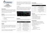
VERSITRON SF71060M & SF71060MP
Revision A3
SF71060M & SF71060MP
Industrial 10-Port 10/100/1000Base
Managed PoE/PoE+ Switch
with 100/1000Base SFP Slots
I
I
n
n
s
s
t
t
a
a
l
l
l
l
a
a
t
t
i
i
o
o
n
n
G
G
u
u
i
i
d
d
e
e
v
v
1
1
.
.
0
0
0
0
© November 2017
VERSITRON, Inc.
83 Albe Drive / Suite C
Newark, DE 19702
www.versitron.com

ii
VERSITRON SF71060M & SF71060MP
Revision A3
Copyright VERSITRON, Inc. All rights reserved. All brand and product names are trademarks or
registered trademarks of their respective companies.
PROPRIETARY DATA
All data in this manual is proprietary and may not be disclosed,
used or duplicated, for procurement or manufacturing purposes,
without prior written permission by VERSITRON.
VERSITRON LIFETIME WARRANTY
All VERSITRON products are covered by a Lifetime Warranty against defects in materials and
workmanship. This coverage is applicable to the original purchaser and is not transferable.
We repair, or at our option, replace parts/products that, during normal usage and operation, are proven
to be defective during the time you own the products, provided that said products and parts are still
manufactured and/or available. Such repair/replacement is subsequent to receipt of your product at
our facility and our diagnostic evaluation and review of the unit. Advance replacements are not
provided as part of the warranty coverage.
This warranty does not cover damage to products caused by misuse, mishandling, power surges,
accident, improper installation, neglect, alteration, improper maintenance, or other causes which are
not normal and customary applications of the products and for which they were not intended. No
other warranty is expressed or implied, and VERSITRON is not liable for direct, indirect, incidental or
consequential damages or losses.
In the unlikely event a warranty issue should arise, simply contact us at 302-894-0699 or
(RMA) number, along with instructions for returning your product.

iii
VERSITRON SF71060M & SF71060MP
Revision A3
About This Manual
Copyright
Copyright © 2017 VERSITRON, Inc. All rights reserved.
The products and programs described in this manual are licensed products of
VERSITRON, Inc. This manual contains proprietary information protected by copyright,
and this manual and all accompanying hardware, software and documentation are
copyrighted. No parts of this manual may be copied, photocopied, reproduced,
translated or reduced to any electronic medium or machine-readable from by any
means by electronic or mechanical. Including photocopying, recording, or information
storage and retrieval systems, for any purpose other than the purchaser’s personal use,
and without the prior express written permission of VERSITRON, Inc.
Purpose
This manual gives specific information on how to operate and use the management
functions of the SF71060M & SF71060MP.
Audience
The Manual is intended for use by network administrators who are responsible for
operating and maintaining network equipment; consequently, it assumes a basic
working knowledge of general switch functions, the Internet Protocol (IP), and Simple
Network Management Protocol (SNMP).
Conventions
The following conventions are used throughout this manual to show information.
NOTE: Emphasizes important information or calls your
attention to related features or instructions.
W
ARNING
:
Alerts you to potential hazard that could cause
personal injury.
C
AUTION
:
Alerts you to a potential hazard that could cause
loss of data, or damage the system or equipment.
Warranty
See the VERSITRON, Inc. warranty statement.
Disclaimer
VERSITRON, Inc. does not warrant that the hardware will work properly in all
environments and applications, and marks no warranty and representation, either
implied or expressed, with respect to the quality, performance, merchantability, or
fitness for a particular purpose. VERSITRON, Inc. disclaims liability for any inaccuracies
or omissions that may have occurred. Information in this User’s Manual is subject to
change without notice and does not represent a commitment on the part of
VERSITRON, Inc.. VERSITRON, Inc. assumes no responsibility for any inaccuracies that
may be contained in this User’s Manual. VERSITRON, Inc. makes no commitment to
update or keep current the information in this User’s Manual, and reserves the righter
to make improvements to this User’s Manual and /or to the products described in this
User’s Manual, at any time without notice.

-2-
VERSITRON SF71060M & SF71060MP
Revision A3
TRADEMARKS
Ethernet is a registered trademark of Xerox Corp.
FCC NOTICE
This device complies with Part 15 of the FCC Rules. Operation is subject to the following two conditions: (1) This device may
not cause harmful interference, and (2) This device must accept any interference received, including the interference that
may cause undesired operation.
CE NOTICE
Marking by the symbol indicates compliance of this equipment to the EMC directive of the European Community. Such
marking is indicative that this equipment meets or exceeds the following technical standards:
EMC Class A
EN 61000-6-4:2007/A1:2011
EN 61000-3-2:2006/A1:2009/A2:2009
EN 61000-3-3:2008
EN 61000-6-2:2005
IEC 61000-4-2:2008
IEC 61000-4-3:2010
IEC 61000-4-4:2012
IEC 61000-4-5:2005
IEC 61000-4-6:2008
IEC 61000-4-8:2009
IEC 61000-4-11:2004

-3-
VERSITRON SF71060M & SF71060MP
Revision A3
Table of Contents
0B1. Introduction ...................................................................................................................................................... 4
1.1 Features ............................................................................................................................... 5
1.2 Product Panels ..................................................................................................................... 6
1.3 LED Indicators ...................................................................................................................... 7
1.4 Specifications ....................................................................................................................... 7
1B2. Installation ...................................................................................................................................................... 10
10B2.1 Unpacking .......................................................................................................................... 10
2.2 Safety Cautions .................................................................................................................. 10
12B2.3 DIN-Rail Mounting .............................................................................................................. 11
13B2.4 Panel Mounting .................................................................................................................. 13
14B2.5 Applying Power .................................................................................................................. 15
15B2.6 Alarm Relay Output ............................................................................................................ 17
2.7 Powered via PoE over Cat.5 (Standard Model) .................................................................. 18
2.8 Reset Button ...................................................................................................................... 18
2.9 Making UTP Connections ................................................................................................... 19
2.10 Making Fiber Connection .................................................................................................. 20
2.11 Making PoE PSE Connections (PoE Model) ..................................................................... 22
1306B2.12 LED Indication .................................................................................................................. 23
2.13 Making Console Connection ............................................................................................. 24
3. Manage the Switch ........................................................................................................................................ 25
3.1 IP Address & Password ...................................................................................................... 25
3.2 Configuring IP Address & Password via console and telnet ................................................ 25
3.3 Configuring IP Address via Web Interface .......................................................................... 26
3.4 Reference Manuals for Web, Console, Telnet Management ............................................... 28
3.5 Configuration for SNMP Management ................................................................................ 29
3.6 SNMP MIBs........................................................................................................................ 30

-4-
VERSITRON SF71060M & SF71060MP
Revision A3
0B1. Introduction
The SF71060M & SF71060MP switches are Industrial 10/100/1000Base managed switches featuring:
Eight 10/100/1000Mbps copper ports
Two dual-speed SFP slots for 100Base-FX or 1000Base-X
Model Definitions
Model
Copper
ports
SFP slots
PoE PSE
function
Power via
DC input
Powered via
PoE capable
Software
managed
SF71060M
8
2 dual-speed
-
SF71060MP
8
2 dual-speed
4 PSE ports
-

-5-
VERSITRON SF71060M & SF71060MP
Revision A3
1.1 Features
Eight 10/100/1000Mbps RJ-45 and two dual-speed SFP slots
All copper ports support auto-negotiation and auto-MDI/MDI-X detection.
Two SFP slots support dual speed for 100BASE-FX and 1000BASE-X SFP modules.
Full wire speed forwarding
Supports 802.3x flow control for full-duplex and backpressure for half-duplex
Port link aggregation function with LACP support
Supports SFP with Digital Diagnostic Monitoring (DDM)
Alternatively powered via PoE if direct DC power not available
Optional four 802.3at-compliant PoE+ PSE ports
SNMP private MIB for DDM status, reboot, TFTP firmware update (MIB file Rev1.05 or up)
Optical Power Alarm (OPA) function
Auto Laser Shutdown (ALS) function (supported in H/W Ver.E up)
Management:
- HTTP/HTTPS/SSHv2/CLI telnet/CLI console/SNMP v1/v2c/v3/RMON
- DHCP/DHCPv6 client, DHCP relay, DNS client, NTPv4
- IPv6 support, System Syslog, Configuration down/upload, Software upload
Security:
- NAS, 802.1X, MAC-based/Web/CLI authentication
- IP MAC binding, TACACS+, IP source guard
Layer 2:
- QoS, 802.1Q/MAC-based/Protocol-based/Private/IP subnet VLAN, Port Isolation
- Storm control for UC/MC/BC packets, Static MAC configuration
- IGMP v2/v3 snooping, MLD v1/v2 snooping, DHCP snooping
- Multiple Spanning Tree - MSTP. RSTP, STP
Auto Multi-Ring (KAMR) Technology:
- Fast failover response time, Auto recovery when failure is repaired
- Supports up to five redundant rings, Works with RSTP network

-6-
VERSITRON SF71060M & SF71060MP
Revision A3
1.2 Product Panels
The following figure illustrates the front panel and rear panel of the switch:
SF71060M Front panel
SF71060MP Front panel

-7-
VERSITRON SF71060M & SF71060MP
Revision A3
154BUpper panel
1.3 LED Indicators
LED Function
PWR Power status
Mgt. Management status
Port 1~ 8 SPEED LEDs Speed & PoE status
Port 1~ 8 LINK LEDs Link & activity status
SFP 9, 10 LED Speed & link & activity status of SFP port
1.4 Specifications
10/100/1000 Copper Ports (Port 1 ~ Port 8)
Compliance IEEE 802.3 10Base-T, IEEE 802.3u 100Base-TX, IEEE 802.3u 1000Base-T
Connectors Shielded RJ-45 jacks
Pin assignments Auto MDI/MDI-X detection
Configuration Auto-negotiation or software control
Transmission rate 10Mbps, 100Mbps, 1000Mbps
Duplex support Full/Half duplex
Network cable Cat.5 UTP
Dual-speed SFP Slots (Port 9, Port 10)
Compliance IEEE 802.3u 100Base-FX
IEEE 802.3z 1000Base-SX/LX (mini-GBIC)
Connectors SFP slots for optional SFP fiber modules

-8-
VERSITRON SF71060M & SF71060MP
Revision A3
Configuration Auto 1000Mbps, Full duplex
Forced 100Mbps, Full duplex
Transmission rate 100Mbps and 1000Mbps
Network cables MMF 50/125 60/125, SMF 9/125
Eye safety IEC 825 compliant
Console Port
Interface RS-232, DTE type
Connector Shielded RJ-45
Switch Functions
MAC Addresses Table 8K entries
Forwarding & filtering Non-blocking, full wire speed
Switching technology Store and forward
Maximum packet length 9.6K bytes
IP Multicast groups 8192 supported
Flow control IEEE 802.3x pause frame base for full duplex operation
Back pressure for half duplex operation
Power over Ethernet PSE Function (SF71060MP)
PSE Ports Port 1 ~ Port 4
Power output pins Positive of power voltage: pin 1,2
Negative of power voltage: pin 3,6
Standard IEEE 802.3at
Classification PD Class 0 ~ 4 detection
Power Delivery 30W max. (per port) at port output for Cat.5 distance up to 100 meters
Protection Under voltage protection
Over voltage protection
Over current detection
Powered via Power over Ethernet (SF71060M)
PD Port Port 2
PoE Standard IEEE 802.3af PoE PD (Powered Device)
PSE Support IEEE 802.3af & 802.3at PSE
Power Classification Class 3
Input Voltage (V
poe
) 36 ~ 57VDC via Cat.5

-9-
VERSITRON SF71060M & SF71060MP
Revision A3
Power reception pins Positive of PoE power voltage: pin 1,2,4,5
Negative of power voltage: pin 3,6,7,8
Terminal Block Connector
DC power input Screwed euro terminal block: 2 pairs of +/- contacts
Operating Input Voltages +7 ~ +60VDC (General applications)
+45 ~ +57VDC (PoE applications)
Power consumption 9W max. (Full load with no PoE support)
130W max. (Full load with 4 PoE max. output)
Alarm relay output 2 terminal contacts AR+/AR- (30VDC/1A max. or 120VAC/0.5A max.)
Alarm events Power failure, Specific port link fault (software configured), OPA
* Warning: The -48VDC power supply is not supported.
856BUMechanical
Dimensions 5.51 x 4.17 x 1.65 inches (H x D x W)
Housing Enclosed metal with no fan
Mounting Optional Din-rail mounting or Panel mounting
860BUEnvironmental
Operating Temperature Typical -30℃ ~ +70℃*
Storage Temperature -40℃ ~ +85℃
Relative Humidity 5% ~ 90% non-condensing
* +60
℃
~ +70
℃
with 1m/s air flow
864BUElectrical Approvals
FCC Part 15 rule Class A
CE EMC, CISPR11 Class A
Safety / LVD IEC 60950-1

-10-
VERSITRON SF71060M & SF71060MP
Revision A3
1B2. Installation
10B2.1 Unpacking
The product package contains:
One SF71060M or SF71060MP Switch
One console cable
2.2 Safety Cautions
To reduce the risk of bodily injury, electrical shock, fire, and damage to the product, observe the
following precautions.
Do not service any product except as explained in your system documentation.
Opening or removing covers may expose you to electrical shock.
Only a trained service technician should service components inside these compartments.
If any of the following conditions occur, unplug the product from the electrical outlet and replace
the part or contact VERSITRON:
The power cable, extension cable, or plug is damaged.
An object has fallen into the product.
The product has been exposed to water.
The product has been dropped or damaged.
The product does not operate correctly when you follow the operating instructions.
Do not push any objects into the openings of your system. Doing so can cause fire or electric
shock by shorting out interior components.
Operate the product only from the type of external power source indicated on the electrical ratings
label. If you are not sure of the type of power source required, consult VERSITRON or local
power company.

-11-
VERSITRON SF71060M & SF71060MP
Revision A3
12B2.3 DIN-Rail Mounting
An optional DIN-rail mounting bracket can be purchased for mounting the switch in an industrial DIN-rail
enclosure.
The steps to mount the switch onto a DIN rail are:
1. Install the mounting bracket onto the switch as shown below:
2. 1288BAttach the bracket to the lower edge of the DIN rail and push the unit upward until the bracket
can clamp on the upper edge of the DIN rail.
3. Clamp the unit to the DIN rail and make sure it is mounted securely.

-12-
VERSITRON SF71060M & SF71060MP
Revision A3
Dimensions (in mm):

-13-
VERSITRON SF71060M & SF71060MP
Revision A3
13B2.4 Panel Mounting
An optional panel mounting bracket is available for mounting the switch on a flat surface. The mounting steps
are:
1. Install the mounting bracket onto the switch as shown below:
2. 1291BScrew the bracket onto the switch.
3. Screw the switch onto a panel. Three screw locations are shown below:

-14-
VERSITRON SF71060M & SF71060MP
Revision A3
Dimensions (in mm):

-15-
VERSITRON SF71060M & SF71060MP
Revision A3
14B2.5 Applying Power
Pin Assignments of the terminal block connector
Vdc Positive () input terminal
Vdc Negative () input terminal
Vdc Positive () input terminal
Vdc Negative () input terminal
AR+ Alarm relay output positive () terminal
AR Alarm relay output negative () terminal
Any of the Vdc+/Vdc- pairs can be used to receive DC power from an external power system. Or, one can be
used to deliver the power received to another switch in a daisy-chain application.
Vdc Input specifications
Applications
Power per PSE port
DC working voltage
General
-
+7V ~ +60VDC
PoE
15.4W max.
+45V ~ +57VDC (Typical 48V)
High power PoE (PoE+)
30W max.
+45V ~ +57VDC (+52V up for 30W)
WARNING: The -48VDC power supply is not supported.
Caution:
Do not apply direct DC IN power and PoE power at the same time.
Unplug DC IN when PoE power is connected.
Disconnect PoE power when DC IN is used.

-16-
VERSITRON SF71060M & SF71060MP
Revision A3
Three 2P terminal plugs are provided with the switch. Two of the three plugs are used for Vdc interfaces
respectively. The plug is shown below:
184BPower wires : 24 ~ 12AWG (IEC 0.5~2.5mm
2
)
Install the power source wires into the plug properly, and then install the terminal plug into the switch. If
daisy-chaining power to another switch device is required, install the power wires and then install the terminal
plug into each switch. Then, use the other Vdc contacts.
Note:
1. Only up to four device units can be daisy-chained to receive power from one main power input source.
2. The maximal length of the power wire is 1 meter.

-17-
VERSITRON SF71060M & SF71060MP
Revision A3
15B2.6 Alarm Relay Output
An alarm relay output is provided for reporting failure events to a remote alarm relay monitoring system. The
replay output is provided with two contacts in the terminal block connector next to the Vdc interfaces.
Pin Assignments of the Alarm Relay output
AR+ Alarm relay output positive () terminal
AR Alarm relay output negative () terminal
Use the provided 2P terminal plug for signal wiring and plug into the AR+/- contacts.
Alarm Events
Input power failure
Specific port link down (The specific ports can be configured by software.)
OPA alarm if optical power is higher than a upper limit setting or lower than a lower limit setting
Relay Logic
Normal: AR+ and AR- shorted
Alarm: AR+ and AR- open
Note: Be sure the voltage applied on AR+/- contacts is within the specification of 30VDC/1A max. or
120VAC/0.5A max.

-18-
VERSITRON SF71060M & SF71060MP
Revision A3
2.7 Powered via PoE over Cat.5 (SF71060M)
Port 2 is equipped with the function of receiving power from a connected PoE PSE device over Cat.5 cable.
The remote PoE PSE devices can be a mid-span PoE injector or end-span PoE switch.
The switches can support the following PSE:
802.3af compliant PSE (Typical, Type 1 PSE)
Possible voltages received: +36 ~ +57VDC
802.3at compliant PSE (High power PoE, Type 2 PSE)
Possible voltages received: +42.5 ~ +57VDC
2.8 Reset Button
The reset button is used to perform a reset of the switch. It is not used in normal cases and can be used for
diagnostic purposes. If any network problem is suspected, it is useful to push the button to reset the switch
without turning off the power. Check whether the network has recovered.
The button can also be used to restore the software configuration settings to factory default values.
The operations are:
Operation Function
Press the button and release during switch operation Reset & boot up the switch. The behavior is
same as power boot procedure.
Press the button until MNGT-LED is steady ON Boot & restore all factory default settings
/