Supermicro X9SRW-F User manual
- Category
- Server/workstation motherboards
- Type
- User manual

USER’S MANUAL
Revision 1.0b
X9SRW-F

Manual Revision 1.0b
Release Date: February 21, 2013
Unless you request and receive written permission from Super Micro Computer, Inc., you may not
copy any part of this document. Information in this document is subject to change without notice.
Other products and companies referred to herein are trademarks or registered trademarks of their
respective companies or mark holders.
Copyright © 2013 by Super Micro Computer, Inc. All rights reserved.
Printed in the United States of America
The information in this User’s Manual has been carefully reviewed and is believed to be accurate.
The vendor assumes no responsibility for any inaccuracies that may be contained in this document,
makes no commitment to update or to keep current the information in this manual, or to notify any
person or organization of the updates. Please Note: For the most up-to-date version of this
manual, please see our web site at www.supermicro.com.
Super Micro Computer, Inc. ("Supermicro") reserves the right to make changes to the product
described in this manual at any time and without notice. This product, including software and docu-
mentation, is the property of Supermicro and/or its licensors, and is supplied only under a license.
Any use or reproduction of this product is not allowed, except as expressly permitted by the terms
of said license.
IN NO EVENT WILL SUPER MICRO COMPUTER, INC. BE LIABLE FOR DIRECT, INDIRECT,
SPECIAL, INCIDENTAL, SPECULATIVE OR CONSEQUENTIAL DAMAGES ARISING FROM THE
USE OR INABILITY TO USE THIS PRODUCT OR DOCUMENTATION, EVEN IF ADVISED OF
THE POSSIBILITY OF SUCH DAMAGES. IN PARTICULAR, SUPER MICRO COMPUTER, INC.
SHALL NOT HAVE LIABILITY FOR ANY HARDWARE, SOFTWARE, OR DATA STORED OR USED
WITH THE PRODUCT, INCLUDING THE COSTS OF REPAIRING, REPLACING, INTEGRATING,
INSTALLING OR RECOVERING SUCH HARDWARE, SOFTWARE, OR DATA.
Any disputes arising between manufacturer and customer shall be governed by the laws of Santa
Clara County in the State of California, USA. The State of California, County of Santa Clara shall
be the exclusive venue for the resolution of any such disputes. Supermicro's total liability for all
claims will not exceed the price paid for the hardware product.
FCC Statement: This equipment has been tested and found to comply with the limits for a Class B
digital device pursuant to Part 15 of the FCC Rules. These limits are designed to provide reason-
able protection against harmful interference in a residential installation. This equipment generates,
uses, and can radiate radio frequency energy and, if not installed and used in accordance with the
manufacturer’s instruction manual, may cause interference with radio communications. However,
there is no guarantee that interference will not occur in a particular installation. If this equipment
does cause harmful interference to radio or television reception, which can be determined by turn-
ing the equipment off and on, you are encouraged to try to correct the interference by one or more
of the following measures:
•Reorient or relocate the receiving antenna.
•Increase the separation between the equipment and the receiver.
•Connect the equipment into an outlet on a circuit different from that to which the
receiver is connected.
•Consult the dealer or an experienced radio/television technician for help.
California Best Management Practices Regulations for Perchlorate Materials: This Perchlorate warn-
ing applies only to products containing CR (Manganese Dioxide) Lithium coin cells. “Perchlorate
Material-special handling may apply. See www.dtsc.ca.gov/hazardouswaste/perchlorate”.
WARNING: Handling of lead solder materials used in this prod-
uct may expose you to lead, a chemical known to the State of
California to cause birth defects and other reproductive harm.

iii
Preface
Preface
This manual is written for system integrators, PC technicians and
knowledgeable PC users. It provides information for the installation and use of the
X9SRW motherboard series.
About This Motherboard
The X9SRW motherboard series supports a single Intel® E5-1600/E5-
2600 series processor (2011-pin, Socket R). With the Intel® C600 series chipset
built in, the X9SRW Motherboard series offers top-of-the-line system performance
and storage capability. Features such as support for up to 256GB of memory, dual
1Gb LAN, eight (8) USB ports, and an IPMI port make the X9SRW series ideal for
high end rack-mounted single-processor platforms.
Please refer to our website (http://www.supermicro.com/products/) for processor
and memory support updates.
*This product is intended to be installed and serviced by professional technicians.
Manual Organization
Chapter 1describesthefeatures,specicationsandperformanceofthemother-
board, and provides detailed information on the Intel Patsburg chipset.
Chapter 2 provides hardware installation instructions. Read this chapter when in-
stalling the processor, memory modules and other hardware components into the
system. If you encounter any problems, see Chapter 3, which describes trouble-
shooting procedures for video, memory and system setup stored in the CMOS.
Chapter 4 includes an introduction to the BIOS, and provides detailed information
on running the CMOS Setup utility.
Appendix A provides BIOS Error Beep Codes.
Appendix B lists software program installation instructions.
Appendix C contains the UEFI BIOS Recovery instructions.

iv
X9SRW Motherboard Series User’s Manual
Conventions Used in the Manual:
Special attention should be given to the following symbols for proper installation and
to prevent damage done to the components or injury to yourself:
Danger/Caution: Instructions to be strictly followed to prevent catastrophic
system failure or to avoid bodily injury
Warning: Critical information to prevent damage to the components or
data loss.
Important: Important information given to ensure proper system installa-
tion or to relay safety precautions.
Note: Additional Information given to differentiate various models or pro-
vides information for correct system setup.

v
Contacting Supermicro
1-4 Contacting Supermicro
Headquarters
Address: Super Micro Computer, Inc.
980 Rock Ave.
San Jose, CA 95131 U.S.A.
Tel: +1 (408) 503-8000
Fax: +1 (408) 503-8008
Email: [email protected] (General Information)
[email protected] (Technical Support)
Web Site: www.supermicro.com
Europe
Address: Super Micro Computer B.V.
Het Sterrenbeeld 28, 5215 ML
's-Hertogenbosch, The Netherlands
Tel: +31 (0) 73-6400390
Fax: +31 (0) 73-6416525
Email: [email protected] (General Information)
[email protected] (Technical Support)
[email protected] (Customer Support)
Asia-Pacic
Address: Super Micro Computer, Inc.
4F, No. 232-1, Liancheng Rd
Chung-Ho Dist., New Taipei City 235
Taiwan
Tel: +886-(2) 8226-3990
Fax: +886-(2) 8226-3991
Web Site: www.supermicro.com.tw
Technical Support:
Email: [email protected]
Tel: +886-(2)-8226-3990

vi
X9SRW Motherboard Series User’s Manual
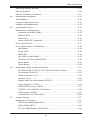
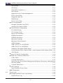
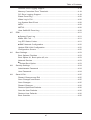
Table of Contents
Preface
About This Motherboard ................................................................................................ iii
Manual Organization .....................................................................................................iii
Conventions Used in the Manual: .................................................................................iv
Contacting Supermicro ...................................................................................................v
Chapter 1
Introduction
1-1 Overview ......................................................................................................... 1-1
Checklist .......................................................................................................... 1-1
Motherboard Features ..................................................................................... 1-7
1-2 Chipset Overview ......................................................................................... 1-10
Intel C600 Chipset Features ......................................................................... 1-10
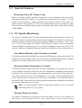
1-3 Special Features ............................................................................................1-11
Recovery from AC Power Loss ......................................................................1-11
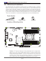
1-4 PC Health Monitoring .....................................................................................1-11
Fan Status Monitor with Firmware Control ...................................................1-11
Environmental Temperature Control ..............................................................1-11
System Resource Alert ..................................................................................1-11
1-5 ACPI Features ............................................................................................... 1-12
Slow Blinking LED for Suspend-State Indicator ........................................... 1-12
1-6 Power Supply ................................................................................................ 1-12
1-7 Super I/O ....................................................................................................... 1-13
Chapter 2
Installation
2-1 Static-Sensitive Devices .................................................................................. 2-1
Precautions ..................................................................................................... 2-1
Unpacking ....................................................................................................... 2-1
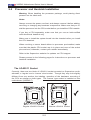
2-2 Processor and Heatsink Installation................................................................ 2-2
The LGA2011 Socket ..................................................................................... 2-2
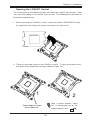
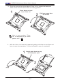
Opening the LGA2011 Socket ....................................................................... 2-3
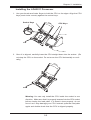
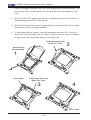
Installing the LGA2011 Processor ................................................................. 2-5
Installing a Passive CPU Heatsink ................................................................. 2-7
Removing the Heatsink ................................................................................... 2-8
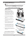
2-3 Installing DDR3 Memory ................................................................................. 2-9
DIMM Installation ............................................................................................ 2-9

vii
Table of Contents
Removing Memory Modules ........................................................................... 2-9
Memory Support ............................................................................................ 2-10
Memory Population Guidelines ......................................................................2-11
2-4 Motherboard Installation ................................................................................ 2-12
Tools Needed ................................................................................................ 2-12
Location of Mounting Holes .......................................................................... 2-12
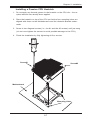
Installing the Motherboard ............................................................................ 2-13
2-5 Connectors/IO Ports ...................................................................................... 2-14
Motherboard I/O Backpanel .......................................................................... 2-14
Universal Serial Bus (USB) ...................................................................... 2-15
Ethernet Ports .......................................................................................... 2-16
Serial Port ................................................................................................. 2-16
Video (VGA/CRT) Connector ................................................................... 2-16
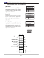
Front Control Panel ....................................................................................... 2-17
FrontControlPanelPinDenitions............................................................... 2-18
NMI Button ............................................................................................... 2-18
Power LED .............................................................................................. 2-18
HDD LED .................................................................................................. 2-18
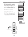
NIC1/NIC2 (LAN1/LAN2) .......................................................................... 2-19
Overheat (OH)/Fan Fail/UID LED ............................................................ 2-19
Reset Button ........................................................................................... 2-20
Power Button ........................................................................................... 2-20
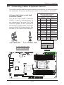
2-6 Connecting Cables & Optional Devices ........................................................ 2-21
ATX Main PWR (JPW1) & CPU PWR Connectors (JPW2) ..................... 2-21
Fan Headers (FAN1~6) ............................................................................ 2-22
Chassis Intrusion (JL1) ............................................................................ 2-22
Speaker (JD1) .......................................................................................... 2-23
Legacy Wake-On-LAN Header (JSTBY) .................................................. 2-23
Power Supply I
2
C (JPI2C) ........................................................................ 2-24
DOM PWR Connector (JSD1) .................................................................. 2-24
T-SGPIO 1/2 & 3-SGPIO 1/2 Headers ..................................................... 2-25
TPM Header (JTPM1) .............................................................................. 2-25
Overheat/Fan Fail LED (JOH1) ........................................................ 2-26
2-7 Jumper Settings ............................................................................................ 2-27
Explanation of Jumpers ................................................................................ 2-27
LAN Port Enable/Disable (JPL1) .............................................................. 2-27
Clear CMOS (JBT1) ................................................................................. 2-28
PCI Slot SMB Enable (JI2C2/JI2C3) ........................................................ 2-28

viii
X9SRW Motherboard Series User’s Manual
Watch Dog Reset (JWD) .......................................................................... 2-29
BMC Enable/Disable (JPB1) .................................................................... 2-29
Onboard VGA Enable (JPG1) .................................................................. 2-30
UnitIdentierSwitch(UID) ....................................................................... 2-30
BIOS Recovery (JP3) ............................................................................... 2-31
ME Recovery (JPME1) ............................................................................. 2-31
VRM SMB Clock/Data (J29/J30) .............................................................. 2-31
2-8 Onboard Indicators ........................................................................................ 2-32
LAN Port LEDs ......................................................................................... 2-32
Onboard Power LED (LE1) ...................................................................... 2-32
Rear Unit ID LED (LE2) ........................................................................... 2-33
IPMI Heartbeat LED (BD1) ...................................................................... 2-33
Onboard Standby Power LED (LED2) ..................................................... 2-33
2-9 SATA Connections ......................................................................................... 2-34
SATA/SAS Connections .......................................................................... 2-34
Chapter 3
Troubleshooting
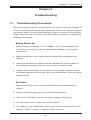
3-1 Troubleshooting Procedures ........................................................................... 3-1
Before Power On ............................................................................................ 3-1
No Power ........................................................................................................ 3-1
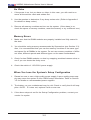
No Video ......................................................................................................... 3-2
Memory Errors ............................................................................................... 3-2
WhenYouLosetheSystem’sSetupConguration ........................................ 3-2
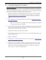
3-2 Technical Support Procedures ........................................................................ 3-3
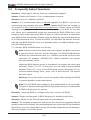
3-3 Frequently Asked Questions ........................................................................... 3-4
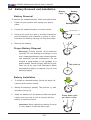
3-4 Battery Removal and Installation .................................................................... 3-6
Battery Removal .............................................................................................. 3-6
Proper Battery Disposal .................................................................................. 3-6
Battery Installation ........................................................................................... 3-6
3-5 Returning Merchandise for Service................................................................. 3-7
Chapter 4
BIOS
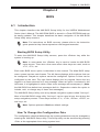
4-1 Introduction ...................................................................................................... 4-1
Starting BIOS Setup Utility .............................................................................. 4-1
HowToChangetheCongurationData ......................................................... 4-1
How to Start the Setup Utility ......................................................................... 4-2
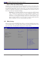
4-2 Main Setup ...................................................................................................... 4-2

ix
Table of Contents
System Overview: The following BIOS information will be displayed: ....... 4-3
System Time/System Date ........................................................................ 4-3
Supermicro X9SRW-F ................................................................................ 4-3
Memory Information ................................................................................... 4-3
Total Memory .............................................................................................. 4-3
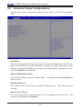
4-3 AdvancedSetupCongurations...................................................................... 4-4
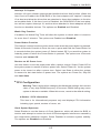
Quiet Boot .................................................................................................. 4-4
AddOn ROM Display Mode ........................................................................ 4-4
Bootup Num-Lock ....................................................................................... 4-4
Wait For 'F1' If Error ................................................................................... 4-4
Interrupt 19 Capture ................................................................................... 4-5
Watch Dog Function ................................................................................... 4-5
Power Button Function ............................................................................... 4-5
Restore on AC Power Loss ........................................................................ 4-5
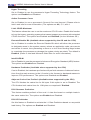
CPUConguration ....................................................................................... 4-5
Socket 1 CPU Information ....................................................................... 4-5
Clock Spread Spectrum ............................................................................. 4-5
Hyper Threading ......................................................................................... 4-6
Active Processor Cores .............................................................................. 4-6
Limit CPUID Maximum ............................................................................... 4-6
Execute-Disable Bit (Available when supported by the OS and the CPU) 4-6
Intel® AES-NI ............................................................................................. 4-6
Hardware Prefetcher (Available when supported by the CPU) ................. 4-6
Adjacent Cache Line Prefetch (Available when supported by the CPU) ... 4-6
DCU Streamer Prefetcher .......................................................................... 4-6
DCU IP Prefetcher...................................................................................... 4-6
Intel® Virtualization Technology (Available when supported by the CPU) 4-7
CPUPowerManagementConguration ................................................. 4-7
Power Technology ...................................................................................... 4-7
EIST ............................................................................................................ 4-7
Turbo Mode ................................................................................................ 4-7
C1E Support ............................................................................................... 4-7
CPU C3 Report, CPU C6, CPU C7 Report ............................................... 4-7
Package C State Limit ............................................................................... 4-7
ChipsetConguration ................................................................................... 4-8
SATAConguration .....................................................................................4-11
SATA Port0~Port5 .....................................................................................4-11

x
X9SRW Motherboard Series User’s Manual
SATA Mode ................................................................................................4-11
IDE Mode ..................................................................................................4-11
Serial-ATA Controller 0~1 ..........................................................................4-11
AHCI Mode ............................................................................................... 4-12
Aggressive Link Power Management ....................................................... 4-12
Port 0~5 Hot Plug..................................................................................... 4-12
Staggered Spin Up ................................................................................... 4-12
RAID Mode ............................................................................................... 4-12
Port 0~5 Hot Plug..................................................................................... 4-12
SCUConguration ..................................................................................... 4-12
Storage Controller Unit (SCU) ................................................................. 4-12
OnChip SCU Option ROM ....................................................................... 4-12
PCIe/PCI/PnPConguration ..................................................................... 4-12
PCI ROM Priority ...................................................................................... 4-12
PCI Latency Timer .................................................................................... 4-13
Above 4G Decoding ................................................................................. 4-13
PERR# Generation ................................................................................... 4-13
SERR# Generation ................................................................................... 4-13
Maximum Payload .................................................................................... 4-13
Maximum Read Request .......................................................................... 4-13
ASPM Support .......................................................................................... 4-13
SXB1 PCI-E 3.0 x16 OPROM ................................................................. 4-13
SXB2 PCI-E 3.0 x8 OPROM ................................................................... 4-13
Onboard LAN Option ROM Select ........................................................... 4-13
Load Onboard LAN1 Option ROM / Load Onboard LAN2 Option ROM . 4-14
VGA Priority .............................................................................................. 4-14
SuperIODeviceConguration ................................................................. 4-14
Serial Port Console Redirection ................................................................. 4-15
COM 1/SOL .............................................................................................. 4-15
Console Redirection ................................................................................. 4-15
Serial Port for Out-of-Band Management/Windows Emergency Management
Services (EMS) ........................................................................................ 4-17
Console Redirection ................................................................................. 4-17
ACPI Settings ............................................................................................. 4-18
High Precision Event Timer ...................................................................... 4-18
ME Subsystem ........................................................................................... 4-18
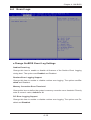
4-4 Event Logs .................................................................................................... 4-19
Change SmBIOS Event Log Settings ........................................................ 4-19
Smbios Event Log .................................................................................... 4-19

xi
Runtime Error Logging Support ............................................................... 4-19
Memory Correction Error Threshold ......................................................... 4-19
PCI Error Logging Support ....................................................................... 4-19
Erase Event Log ....................................................................................... 4-20
When Log is Full ...................................................................................... 4-20
Log System Boot Event ........................................................................... 4-20
MECI ......................................................................................................... 4-20
METW ....................................................................................................... 4-20
View SmBIOS Event Log ......................................................................... 4-20
4-5 IPMI .............................................................................................................. 4-21
System Event Log ................................................................................. 4-21
When SEL Full ......................................................................................... 4-21
Log EFI Status Codes .............................................................................. 4-21
BMCNetworkConguration .................................................................. 4-22
UpdateIPMILANConguration ............................................................... 4-22
CongurationSource ................................................................................ 4-22
4-6 Boot Settings ................................................................................................. 4-23
Boot Options Priorities ............................................................................. 4-23
Boot Option #1, Boot option #2, etc......................................................... 4-23
Network Devices ...................................................................................... 4-23
Delete Boot Option ................................................................................ 4-23
4-8 Security Settings ........................................................................................... 4-24
Administrator Password .......................................................................... 4-24
User Password: ........................................................................................ 4-24
4-8 Save & Exit ................................................................................................... 4-25
Discard Changes and Exit ...................................................................... 4-25
Save Changes and Reset ........................................................................ 4-25
Save Changes .......................................................................................... 4-25
Discard Changes ...................................................................................... 4-26
Restore Optimized Defaults ..................................................................... 4-26
Save As User Defaults ............................................................................. 4-26
Restore User Defaults .............................................................................. 4-26
Boot Override ........................................................................................... 4-26
Table of Contents

xii
X9SRW Motherboard Series User’s Manual
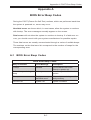
Appendix A
BIOS Error Beep Codes
A-1 BIOS Error Beep Codes .................................................................................A-1
Appendix B
Software Installation Instructions
B-1 Installing Drivers ..............................................................................................B-1
B-2 ConguringSuperDoctor
®
III .......................................................................... B-2
Appendix C
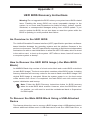
UEFI BIOS Recovery Instructions
An Overview to the UEFI BIOS ..................................................................................C-1
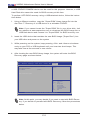
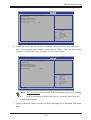
How to Recover the UEFI BIOS Image (-the Main BIOS Block) ...............................C-1
To Recover the Main BIOS Block Using a USB-Attached Device .............................C-1

Chapter 1: Introduction
1-1
Chapter 1
Introduction
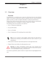
1-1 Overview
Checklist
Congratulations on purchasing your computer motherboard from an acknowledged
leader in the industry. Supermicro boards are designed with the utmost attention to
detail to provide you with the highest standards in quality and performance.
Please check that the following items have all been included with your motherboard.
If anything listed here is damaged or missing, contact your retailer.
The following items are included in the retail box.
•One (1) Supermicro Mainboard
•Six (6) SATA cables
•One (1) I/O shield
•One (1) Supermicro CD containing drivers and utilities
Note: For your system to work properly, please follow the links below to
download all necessary drivers/utilities and the user's manual for your
motherboard.
•SMCI product manuals: http://www.supermicro.com/support/manuals/
•Product Drivers and utilities: ftp://ftp.supermicro.com/
Warning: For safety considerations, please refer to the complete list of
safety warnings posted on the Supermicro website at http://www.supermi-
cro.com/about/policies/safety_information.cfm.
If you have any questions, please contact our support team at support@supermicro.
com.

1-2
X9SRW Motherboard Series User’s Manual
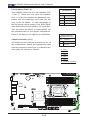
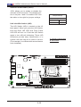
Note: All graphics shown in this manual were based upon the latest PCB
Revision available at the time of publishing of the manual. The motherboard
you've received may or may not look exactly the same as the graphics
shown in this manual.
Motherboard Image

Chapter 1: Introduction
1-3
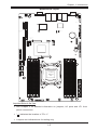
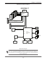
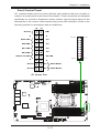
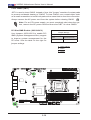
Motherboard Layout
Important Notes to the User
•See Chapter 2 for detailed information on jumpers, I/O ports and JF1 front
panel connections.
•" " indicates the location of "Pin 1".
•Jumpers not indicated are for testing only.
JLAN1JLAN2
14
JUIDB1
JSTBY1
1
3
JIPMB1
JI2C1
1
5
Socket R
LGA 2011
CPU
DESIGNED IN USA
SXB2
SXB1B
1
JD1
JPWR1
1
T-SGPIO4
7
1
T-SGPIO3
7
1
T-SGPIO1
8
7
2
1
T-SGPIO2
87
1
JF1
1
2
19
20
JUSBKM
24
SXB1A
SAS2
SAS1
SAS3
SAS4
J17
H-HS2_2
SP1
JBT1
BD1
A
C
LED2
LE2
LE1
BT1
+
JOH1
JL1
1
R136
JVGA1
JTPM1
J26
J23
1
JCOM1
FAN5
FAN4
4
FAN3
FAN2
FAN1
JWF1
1
J4
J2
J3
J1
C241
JWP1
3
JI2C3
JI2C2
1
3
JPG1
JPB1
JP3
JPME1
JWD
JPL1
1
3
SXB1B: LEFT_WIO_MIDDLE
SXB2: RIGHT_WIO
SXB1A: LEFT_WIO_UP
WRITE PROTECT
JWP1:
USB
USB
1-2:RST
2-3:NIMI
JWD:
JI2C2/JI2C3
1-2:Enable
2-3:Disable
JPMB
OFF:NORMAL
ON:ME RECOVERY
JPME1:
VGA
UID
JTPM1: TPM/PORT80
DIMM4A
DIMM4B
DIMM3B
DIMM3A
KB/MOUSEUSB/2/3
JTPM1:TPM/PORT80
JSTBY1:STAND BY POWER FOR DOM
2-3:NMI
1-2:RST(DEFAULT)
JWD:WATCH DOG TIMER
JD1:
4-7:SPEAKER
1-2:PWR_LED
IPMI LAN
USB/0/1
1-2:ENABLE
2-3:DISABLE
JPL2:LAN2
JPL1:LAN1
2-3:DISABLE
1-2:ENABLE
JPB1: BMC
COM1
JBT1:CMOS CLEAR
LAN2
JL1
LAN1
DIMM2B
DIMM2A
JI2C1
2-3:Disable
1-2:Enable
JOH1:OVER HEAT LED
CPU
OFF:Disable
ON:Enable
2-3:DISABLE
1-2:ENABLE
:CHASSIS INTRUSION
I-SATA3
I-SATA4
I-SATA2
I-SATA1
I-SATA0
I-SATA5
DIMM1B
DIMM1A
JPG1: VGA
J29
1
3
J30
1
3
CPU1
CLOSE 1st
OPEN 1st

1-4
X9SRW Motherboard Series User’s Manual
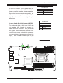
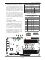
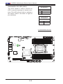
Motherboard Quick Reference
JLAN1JLAN2
14
JUIDB1
JSTBY1
1
3
JIPMB1
JI2C1
1
5
Socket R
LGA 2011
CPU
DESIGNED IN USA
SXB2
SXB1B
1
JD1
JPWR1
1
T-SGPIO4
7
1
T-SGPIO3
7
1
T-SGPIO1
8
7
2
1
T-SGPIO2
87
1
JF1
1
2
19
20
JUSBKM
24
SXB1A
SAS2
SAS1
SAS3
SAS4
J17
H-HS2_2
SP1
JBT1
BD1
A
C
LED2
LE2
LE1
BT1
+
JOH1
JL1
1
R136
JVGA1
JTPM1
J26
J23
1
JCOM1
FAN5
FAN4
4
FAN3
FAN2
FAN1
JWF1
1
J4
J2
J3
J1
C241
JWP1
3
JI2C3
JI2C2
1
3
JPG1
JPB1
JP3
JPME1
JWD
JPL1
1
3
SXB1B: LEFT_WIO_MIDDLE
SXB2: RIGHT_WIO
SXB1A: LEFT_WIO_UP
WRITE PROTECT
JWP1:
USB
USB
1-2:RST
2-3:NIMI
JWD:
JI2C2/JI2C3
1-2:Enable
2-3:Disable
JPMB
OFF:NORMAL
ON:ME RECOVERY
JPME1:
VGA
UID
JTPM1: TPM/PORT80
DIMM4A
DIMM4B
DIMM3B
DIMM3A
KB/MOUSEUSB/2/3
JTPM1:TPM/PORT80
JSTBY1:STAND BY POWER FOR DOM
2-3:NMI
1-2:RST(DEFAULT)
JWD:WATCH DOG TIMER
JD1:
4-7:SPEAKER
1-2:PWR_LED
IPMI LAN
USB/0/1
1-2:ENABLE
2-3:DISABLE
JPL2:LAN2
JPL1:LAN1
2-3:DISABLE
1-2:ENABLE
JPB1: BMC
COM1
JBT1:CMOS CLEAR
LAN2
JL1
LAN1
DIMM2B
DIMM2A
JI2C1
2-3:Disable
1-2:Enable
JOH1:OVER HEAT LED
CPU
OFF:Disable
ON:Enable
2-3:DISABLE
1-2:ENABLE
:CHASSIS INTRUSION
I-SATA3
I-SATA4
I-SATA2
I-SATA1
I-SATA0
I-SATA5
DIMM1B
DIMM1A
JPG1: VGA
J29
1
3
J30
1
3
CPU1
CLOSE 1st
OPEN 1st
JI2C3
JI2C2
JPG1
LED2
SXB1A
I-SAS0
I-SAS1
I-SAS2 I-SAS3
I-SATA0
I-SATA2
I-SATA4
I-SATA1
I-SATA3
I-SATA5
JSD1
JL1
FAN5
FAN4
JF1
FAN3
FAN2 FAN1
JPW1
JPW2
JPI2C1
T-SGPIO1
T-SGPIO2
T-SGPIO3
T-SGPIO4
JSTBY1
JWP1
JPL1
USB4/5
USB8/9
JIPMB1
JTPM1
JBT1
JD1
SP1
BT1
JPME1
JPB1
JWD
JOH1
BD1
SXB2
SXB1B
UID
LE2
JVGA1
JLAN2
JLAN1
USB2/3
USB0/1
IPMI
JCOM1
LE1
JP3
J30
J29

Chapter 1: Introduction
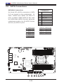
1-5
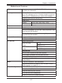
Motherboard Headers/Connectors
Connector Description
I-SAS0~I-SAS3 (SATA 3.0) I-SATA 3.0 ports (supports up to 6Gb/s)
I-SATA0, I-SATA1 (SATA 3.0)
I-SATA2~I-SATA5 (SATA 2.0)
Internal SATA ports (I-SATA0 and I-SATA1 supports up to
6Gb/s), I-SATA2~I-SATA5 supports upo to 3Gb/s)
FAN1~FAN5 Headers for system cooling fans
JSD1 SATA DOM (Disk On Module) Power Connector
JL1 Chassis Intrusion Header
JF1 Front Panel Control Header
JPW1 24-pin Main ATX Power Connector
JPW2 8-pin Secondary Power Connector
JD1 Power LED / Speaker Header (Pins 4~7: External Speaker)
JPI2C1 Power Supply SMBus I2C Header
T-SGPIO1~4 Serial Link General Purpose I/O Headers (5V Gen1/Gen 2)
JTPM1 Trusted Platform Module (TPM) Header
JSTBY1 Legacy Wake On LAN Header
USB0/1, USB2/3 Back panel USB 2.0 ports
USB4/5, USB4/5 Internal USB 2.0 headers
JIPMB System Management Bus Header for the IPMI Slot
JCOM1 Back panel Serial Port Connector
IPMI Back panel IPMI LAN Port
JLAN1/JLAN2 Back panel LAN1 / LAN2 Ethernet Ports
JVGA1 Back panel VGA Port
JOH1 Overheat LED/Fan Fail
BT1 System Battery
SP1 Internal Speaker / Buzzer
SXB1A, SXB1B Slot for Supemicro riser card P/N RSC-R1UW-2E16
SXB2 Slot for Supemicro riser card P/N RSC-R1UW-E8R

1-6
X9SRW Motherboard Series User’s Manual
Motherboard Jumpers
Jumper Description Default
JI2C2/JI2C3 SMB to PCI Slots On (Enabled)
JPG1 Onboard VGA Enable Pins 1-2 (On)
JPL1 LAN1 Enable Pins 1-2 (Enabled)
JPME1 Intel ME Mode Select Pins 1-2 (Normal)
UID Unit ID Switch Off (Disabled)
JWD Watch Dog Timer Reset Pins 1-2 (Reset)
JPB1 IPMI/BMC Enable Pins 1-2 (Enabled)
JP3 BIOS Recover Pins 2-3 (Normal)
JWP1 BIOS Write Protect Pins 1-2 (Normal)
JBT1 CMOS Clear See Chapter 2
J29 VRM SMB Clock (to BMC or PCH) Pins 1-2 (BMC, Normal)
J30 VRAM SMB Data (to BMC or PCH) Pins 1-2 (BMC, Normal)
Motherboard LED Indicators
LED Description Color/State Status
LED2 Standby 3.3V Power Green/Steady Standby Power
LE1 Power LED Green/Steady System is On/Running
LE2 UID LED Blue/Steady UID Switch is On
BD1 IPMI Heartbeat Green/Blinking IPMI is enabled

Chapter 1: Introduction
1-7
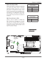
Motherboard Features
CPU Supports a single Intel® E5-1600/E5-2600 series proces-
sor (2011-pin, Socket R)
Memory Eight (8) DIMM slots support up to 256GB of DDR3 Unbuf-
fered, ECC RDIMM memory or 64GB of DDR3 Unbuffered,
ECC/non-ECC UDIMM memory, 1066/1333/1600MHz..
Supports dual-channel memory bus
DIMM sizes
UDIMM 1GB, 2GB, 4GB, 8GB, 16GB
RDIMM 2GB, 4GB, 8GB, 16GB, 32GB, 64GB
Chipset Intel® C600-D or C600-A
Expansion PCI Slots (using riser cards)
Two (2) PCI-Express 3.0 x16 Slot, using Supemicro riser
card P/N RSC-R1UW-2E16
One (1) PCI-Express 2.0 x8 Slot, using Supermicro riser
card P/N RSC-R1UW-E8R
Network Connections Integrated LAN
One (1) Intel i350 Dual Gb LAN
I/O Devices SATA Connections
SATA 3.0 Ports Six (6)
6 Gb/s RAID 0, 1, 5
SATA 2.0 Ports Four (4)
3 Gb/s No RAID support
USB Devices
Two (2) USB 2.0 ports on the rear I/O panel
Six (6) USB 2.0 headers for front panel access
Serial (COM) Ports
One (1) Fast UART 16550 connection on the I/O back
panel (COM1)
BIOS 32 Mb SPI AMI BIOS
®
SM Flash BIOS
Plug and Play APM 1.2, DMI 2.3, PCI 2.2, ACPI 1.0/2.0,
USB Keyboard and SMBIOS 2.3
Power Conguration ACPI/ACPM Power Management
Wake On LAN (WOL) Header
Keyboard Wake-up from Soft-Off
CPU Fan Auto-off in Sleep Mode
Power-on mode for AC power recovery

1-8
X9SRW Motherboard Series User’s Manual
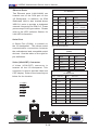
PC Health Monitoring CPU & Chassis Monitoring
Onboard voltage monitors for CPU core, +1.8V, +3.3V,
+5V, +/-12V, +3.3V Stdby, +5V Stdby, VBAT, Memory,
Chipset
CPU 5-phase switching voltage regulator
CPU/System overheat LED and control
CPU Thermal Trip support
CPU & Chassis Environment Monitor
Fan Control
Fan status monitoring with rmware 4-pin (Pulse Width
Modulation) fan speed control
Low noise fan speed control
System Management PECI 2.0 support
System resource alert via Supero Doctor III
SuperoDoctor III, Watch Dog, NMI
Chassis Intrusion header and detection
CD Utilities BIOS ash upgrade utility
Drivers and software for Intel® C204 chipset utilities
Other ROHS 6/6 (Full Compliance, Lead Free)
TPM 1.2 header on board
DOM (Disk on Module) Power Connector Support
FCC B, EuP Lot 6, WHQL
Dimensions WIO form factor (8.15" x 13.05")
Page is loading ...
Page is loading ...
Page is loading ...
Page is loading ...
Page is loading ...
Page is loading ...
Page is loading ...
Page is loading ...
Page is loading ...
Page is loading ...
Page is loading ...
Page is loading ...
Page is loading ...
Page is loading ...
Page is loading ...
Page is loading ...
Page is loading ...
Page is loading ...
Page is loading ...
Page is loading ...
Page is loading ...
Page is loading ...
Page is loading ...
Page is loading ...
Page is loading ...
Page is loading ...
Page is loading ...
Page is loading ...
Page is loading ...
Page is loading ...
Page is loading ...
Page is loading ...
Page is loading ...
Page is loading ...
Page is loading ...
Page is loading ...
Page is loading ...
Page is loading ...
Page is loading ...
Page is loading ...
Page is loading ...
Page is loading ...
Page is loading ...
Page is loading ...
Page is loading ...
Page is loading ...
Page is loading ...
Page is loading ...
Page is loading ...
Page is loading ...
Page is loading ...
Page is loading ...
Page is loading ...
Page is loading ...
Page is loading ...
Page is loading ...
Page is loading ...
Page is loading ...
Page is loading ...
Page is loading ...
Page is loading ...
Page is loading ...
Page is loading ...
Page is loading ...
Page is loading ...
Page is loading ...
Page is loading ...
Page is loading ...
Page is loading ...
Page is loading ...
Page is loading ...
Page is loading ...
Page is loading ...
Page is loading ...
Page is loading ...
Page is loading ...
Page is loading ...
Page is loading ...
Page is loading ...
Page is loading ...
Page is loading ...
Page is loading ...
Page is loading ...
Page is loading ...
-
 1
1
-
 2
2
-
 3
3
-
 4
4
-
 5
5
-
 6
6
-
 7
7
-
 8
8
-
 9
9
-
 10
10
-
 11
11
-
 12
12
-
 13
13
-
 14
14
-
 15
15
-
 16
16
-
 17
17
-
 18
18
-
 19
19
-
 20
20
-
 21
21
-
 22
22
-
 23
23
-
 24
24
-
 25
25
-
 26
26
-
 27
27
-
 28
28
-
 29
29
-
 30
30
-
 31
31
-
 32
32
-
 33
33
-
 34
34
-
 35
35
-
 36
36
-
 37
37
-
 38
38
-
 39
39
-
 40
40
-
 41
41
-
 42
42
-
 43
43
-
 44
44
-
 45
45
-
 46
46
-
 47
47
-
 48
48
-
 49
49
-
 50
50
-
 51
51
-
 52
52
-
 53
53
-
 54
54
-
 55
55
-
 56
56
-
 57
57
-
 58
58
-
 59
59
-
 60
60
-
 61
61
-
 62
62
-
 63
63
-
 64
64
-
 65
65
-
 66
66
-
 67
67
-
 68
68
-
 69
69
-
 70
70
-
 71
71
-
 72
72
-
 73
73
-
 74
74
-
 75
75
-
 76
76
-
 77
77
-
 78
78
-
 79
79
-
 80
80
-
 81
81
-
 82
82
-
 83
83
-
 84
84
-
 85
85
-
 86
86
-
 87
87
-
 88
88
-
 89
89
-
 90
90
-
 91
91
-
 92
92
-
 93
93
-
 94
94
-
 95
95
-
 96
96
-
 97
97
-
 98
98
-
 99
99
-
 100
100
-
 101
101
-
 102
102
-
 103
103
-
 104
104


Supermicro X9SRW-F User manual
- Category
- Server/workstation motherboards
- Type
- User manual
Ask a question and I''ll find the answer in the document
Finding information in a document is now easier with AI
Related papers
-
Supermicro X9SRW-F Quick Reference Manual
-
-
-
-
Supermicro X7SLM Quick Reference Manual
-
Supermicro MBD-X9SRA-B User manual
-
-
-
-
Supermicro X9DRW-3F User manual
Other documents
-
Super Talent Technology RM64G-BK_R Datasheet
-
-
-
-
-
Gemini GEMD19 Datasheet
-
Gigabyte GA-6UASL3 User manual
-
Integral INFD8GBFUS3.0 Datasheet
-
-