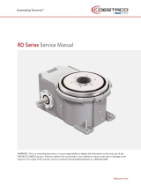
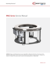
DESTACO CAMCO GENERAL User manual

Type
User manual
GENERAL SERVICE MANUAL
CAMCO INDEX DRIVES
WARNING
This is a controlled document. It is your responsibility to deliver this information to the end user of the DESTACO
CAMCO or FERGUSON product. Failure to deliver this could result in your liability for injury to the user or damage to
the machine. For copies of this manual, call your Customer Service Representative at 800-645-5207
1
Table of Contents
Introduction .......................................................................................................................... 2
How to Use This Service Manual ......................................................................................... 2
Warranty ............................................................................................................................... 2
Warnings and Cautions ........................................................................................................ 3
Interpretation of Index Drive Model Numbers ....................................................................... 3
Index Drive Basic Service Requirements ............................................................................. 4
Inspection of Cam Followers ................................................................................................ 4
Index Drive Lubrication Data ................................................................................................ 5
Index Drive Oil Capacities (Approximate) ............................................................................. 6
Oil Seal Installation Recommendations ................................................................................ 6
Gear Reducer Service Data ................................................................................................. 7
Gear Reducer Lubrication Data ............................................................................................ 8
Overload Clutch ................................................................................................................... 9
Long Term Reducer/Indexer Storage ................................................................................... 9
Troubleshooting Guide ....................................................................................................... 10
Recommended Input Configuration .................................................................................... 12
Recommended Output Configuration ................................................................................. 13
Cam & Limit Switch Functions ............................................................................................ 14
How to Order Parts ............................................................................................................. 15
How to Return Equipment for Repair .................................................................................. 16
Indexer Weights ................................................................................................................. 17
Recommended Tightening Torque Values for Cap Screws ................................................ 18
Cam Follower Installation Procedure .................................................................................. 19
2
Introduction
DESTACO CAMCO Index Drives are engineered and manufactured to very high tolerances which
necessitate careful inspection and maintenance. This manual is a general guide to lubrication,
troubleshooting and general information about index drives.
In addition to this General Service Manual, DESTACO has other service manuals devoted to the
specific model CAMCO index drive you are using. The model-specific service manuals cover
disassembly and assembly of the major components. They also contain an exploded view drawing of
the index drive with a complete bill of materials for identifying and ordering spare or replacement
parts.
Some users of index drives have the facilities and trained personnel to accomplish service repair.
You must determine the extent to which intricate servicing should be done in your own facility. When
in doubt, DESTACO recommends that DESTACO trained service technicians make the repairs.
How to Use This Service Manual
1. This manual deals covers general service and maintenance subjects. In addition to this manual
you should have the model-specific service manual. You may request a copy from your local
DESTACO Sales Representative, directly from DESTACO CAMCO Products (847-459-5200 /
[email protected]) or download a copy from destaco.com.
2. The Model Number Interpretation section will assist you in identifying the model you have and the
characteristics of your index drive
3. The Troubleshooting Guide will help you diagnose potential problems.
4. This manual will explain how to order parts or return an Index Drive to DESTACO for repair.
IMPORTANT: The Bill of Materials listed in the model-specific service manual is for a standard
unit. If you feel you have a special unit, or are in doubt, please use the procedures outlined in the
“How to Order Parts” section.
5. Read all CAUTIONS and WARNINGS prior to service or repair.
6. Read WARRANTY prior to service or repair.
Warranty
DESTACO products are warranted for one (1) year from the date of shipment to be free from defects
in workmanship and materials
The foregoing warranty is exclusive and in lieu of all other warranties, whether written or orally
expressed or implied and there are no warranties of merchantability or fitness for particular use.
DESTACO’s obligation under the foregoing is limited to replace free of charge, including the lowest
transportation cost, but not including installation or any other charges, any part that our inspection
shows to be defective provided that the part was properly installed, suitably maintained and not
subject to misuse or abuse, and further provided that the defective parts are returned to our plant
within one (1) year after delivery by us. Written permission for such return must first be obtained from
DESTACO. A complete explanation is required of the alleged defects and circumstances.
See the "How to Return for Repair" section of this manual.
3
Warnings and Cautions
Statements in this manual preceded by the words WARNING or CAUTION and printed in italics are very
important. We recommend you take special notice of these during service or repair.
WARNING
Means there is the possibility of personal injury to yourself or others.
CAUTION
Means there is the possibility of damage to the CAMCO unit.
Interpretation of Index Drive Model Numbers
In an effort to better understand the type of Index Drive you have purchased, the complete model
number as it appears on the name tag can be divided into five (5) main components.
CAMCO EXAMPLE: 250P4H20-270
250 P 4 H20- 270
(1) (2) (3) (4) (5)
1. The basic CAMCO model series, usually the pitch diameter of the cam follower circle (i.e. 250
means 2.5" diameter).
2. The type of cam and output configuration
P = Parallel cam unit
RA = Right angle cam unit
RAD = Right angle cam / dial mounting output
RD = Roller gear cam / dial mounting output
RG = Roller gear cam unit
RDM = Roller gear cam / dial mounting output / motorized
RNG = Ring index drive
E = Heavy duty right angle cam units / dial mounting
3. The number of stops.
Four (4) stops means the output shaft will make four starts and stops during one complete
360 degree revolution. The angle of each segment of output rotation (index distance) is found
by dividing 360 by the number of stops.
EXAMPLE: 4 stops = 360/4 = 90° per index
4. Cam follower size in 32nds of an inch.
For example
H20 = 20/32 = .625 inch diameter followers
H96 = 96/32 = 3.00 inch diameter followers
5. Cam motion in degrees.
The cam is divided into two basic parts, motion and dwell. Motion is the angular segment in
which the cam does its work rotating the output shaft one complete index.
4
After motion is complete the cam is considered to be in dwell for the reminder of the 360°
rotation. During dwell the output of the Index Drive is stationary even though the input shaft
continues to rotate.
Example: For a 270° motion, during 270° of input rotation the output shaft makes one index.
During the remaining 90° of input rotation the output is stationary.
IMPORTANT NOTE: Some CAMCO units are called "type 2" units. In this case the cam has
two motion periods and two dwell periods on the cam.
Example: 250P6H20-270 Type 2 (also shown as Type II)
For 135° on input rotation the output shaft makes one index. During the next 45° of input
rotation the output does not move. For the next 135° of input rotation the output makes a
second index. During the next 45° of input rotation the output does not move. In summary,
two complete cycles of index and dwell are provided for one rotation of the input shaft.
Therefore, 50RPM at the input (cam) shaft equals 100 indexes/minute.
Index Drive Basic Service Requirements
1. The Index Drive oil level should be checked monthly and oil added as required to maintain proper
level.
2. The oil should be changed as outlined in the lubrication section.
3. All grease fittings should be lubricated with the recommended grease once per month.
4. All index drive mounting bolts should be checked for tightness after three months of service and
annually thereafter.
5. Cam followers should be inspected every 8000 hours of operation.
Inspection of Cam Followers
The cam followers should be inspected every 8000 hours of operation. Backlash at any station
indicates worn or damaged cam followers. Any binding during rotation of the input shaft could indicate
broken cam followers.
To inspect for excessive backlash, place the indexer in a dwell position and check for looseness by
physically trying to force the dial or crank arm back and forth. Excessive looseness (.0015” at 6"
radius) indicates replacement of the cam followers is required and the Index Drive should be returned
to DESTACO for repair.
Contact your local DESTACO representative for assistance if necessary.
5
Index Drive Lubrication Data
OIL LEVEL
CAMCO Index Drives are furnished with a "bulls-eye" type oil level sight gauge. The oil level should
be checked when the unit is stopped at which time the oil level should reach the center of the sight
glass (see page 3 for estimated oil capacity). During oil changes this "bulls-eye" can be removed for
cleaning.
CAUTION: CAMCO units are shipped without oil. Be sure to fill prior to initial startup.
OIL CHANGE
An oil change is required every 2000 hours of operation, or every six months whichever occurs first.
Where operating conditions are severe, such as rapid rise and fall in temperature of the indexer
housing (which is accompanied by sweating of the inside walls with a resulting formation of sludge),
where operation is in moist and dusty atmospheres, or in the presence of chemical fumes, it may be
necessary to change the oil in intervals of one to three months.
NOTE: The magnetic drain plug should be visually inspected at this time for metallic chips that
might indicate failure of one of the internal components.
TYPE OF OIL
Lubricating oils should be high quality, well-refined petroleum oils or synthetic lubricants with
extreme pressure additives. They may be subjected to high operating temperatures, so they must
have good resistance to oxidation.
DESTACO recommends the following:
General applications: Oil that meets API-GL-5 and Mil Spec 2105D/E parameters such as
Mobilube HD Plus 80W90 (conventional) or Mobil Delvac Synthetic Gear Oil 75W90
(synthetic)
Servo-controlled applications: use Mobil SHC 634 (Exxon-Mobil).
NOTE: When the gear reducer and Index Drive have a common oil reservoir (as with the
902RDM Index Drive and the R250 reducer), an AGMA #8 compound is recommended. One
such lubricant is Exxon-Mobil's 600 W SUPER CYLINDER OIL.
NOTE: If you cannot locate the oil listed your supplier should be able to cross reference to
another brand.
NOTE: For lubricants used in Gear Reducers not sharing common oil with Index Drives see
the GEAR REDUCER SERVICE SECTION. DO NOT use oils with EP Additives in Gear
Reducers.
GREASE PACKED BEARINGS
Bearings that are accessed by oil in the indexer reservoir require no additional maintenance. Bearings
not lubricated by the oil in this way are normally packed with a high quality bearing grease. However,
bearings that are not lubricated by the oil reservoir or by grease packing will require periodic
greasing. Bearings of this type will be furnished with a grease fitting and should be greased with
NGLI #2 bearing grease (such as MOBILGREASE XHP222) at least once per month. Do not over lube
since the excess grease will eventually fall into the indexer oil reservoir.
6
Index Drive Oil Capacities (Approximate)
For indexers mounted in the normal* position. Consult DESTACO for units not listed.
Model No. US. Metric Model No. U.S. Metric
(quarts) (liters) (quarts) (liters)
80RDM Grease filled** 40RGD/S 6 oz. 0.2
601RDM 2 2 50RGD/S 16 oz. 0.5
902RDM 3 3 70RGD/S 20-24 oz. 0.6-0.7
1100RDM 8 8 80RGD/S 30-38 oz. 1-1.1
1305RDM 9 9 110RGD/S C/F C/F
1800RDM 36 34
350RGD/S 1 1.4
425RD 2 2 500RGD/S 5 4.7
800RD 5 5 700RGD/S 10 9.5
1301RD 14 13
1801RD 36 34 1100RNG C/F C/F
1550RNG C/F C/F
250P 1 1 2050RNG C/F C/F
387P 2 2
512P 5 5 750E C/F C/F
662P 10 10 950E 10 gallons 38
900P 20 19 1150E 25 gallons 95
1200P 48 45 1550E 40 gallons 152
1800P 95 90 2050E 45 gallons 171
2750E 75 gallons 285
401RA (C) 1 1
512RA(CC) 2 2 150RPP 2.5 2.4
662RA(CCM) 6 6 300RPP 4 4
663RAD(DR) 4 4 500RPP 10 9
900RAD(GH) 6 6 900RPP 48 45
* Normal indexer mounting position is output vertical over input on all models except the "Parallel series" (P)
in which normal mounting is output horizontal, even with input. “Output Vertical” refers to the direction of the
center of rotation. For dial-type indexers, this is the position with the dial horizontal.
** “Grease-filled” units are shipped with grease. Grease should only need to be added if the unit is
disassembled for rebuild or repair.
C/F: Consult DESTACO for information
Oil Seal Installation Recommendations
DESTACO recommends that all seals be replaced any time the device is being disassembled
regardless of whether they are damaged or not. Most damage to oil seals occurs at assembly when
recommended seal installation procedures are not followed.
1. Check dimensions -- to be sure that shaft and bore diameters match those specified for the seal
selected.
2. Check seal -- for damage that may have occurred prior to installation. A sealing lip that is turned
back, cut or otherwise damaged should be replaced.
3. Check bore -- to see that the leading edge is deburred. A rounded corner of chamfer should be
provided.
7
4. Check shaft -- remove surface nicks, burrs and grooves and look for spiral machine marks that
can damage the seal lip.
5. Check shaft end -- remove burrs or sharp edges. The shaft end should be chamfered.
6. Check splines and keyways -- smooth any sharp edges and when necessary protect the seal lip
with an assembly sleeve or shim stock. Round the edges of the spline or keyway as much as
possible and lubricate with a hard, fibrous grease.
7. Check seal direction -- make sure that the new seal faces in the same direction as the original.
Generally, the lip faces the lubricant or fluid to be sealed.
8. Pre-lubricate the sealing element -- before installation by wiping with lubricant being retained.
9. Use the correct installation tool -- press fitting tools should have outside diameter .010" smaller
than the bore size. If possible, the center of tool should be relieved so pressure is applied only at
the outer diameter of the seal.
10. Use proper driving force -- where possible, an arbor press; otherwise, a dead blow hammer to
avoid popping the spring out of the seal. NEVER HAMMER DIRECTLY ON THE SURFACE OF
THE SEAL.
11. Bottom out the tool or seal -- to avoid cocking of the seal in the bore. This also positions the seal
correctly on the shaft.
12. Check for parts interference -- from other machine parts that might rub against the seal causing
friction and damaging heat.
Gear Reducer Service Data
CAMCO Index Drives use two basic makes of reducers. These are CAMCO (R180, R225, R260) and
Cone (7300C, 7350C, etc.). The service data list below is intended to cover both in a general manner.
For other types of reducers, consult the manual supplied with the reducer or contact DESTACO.
1. For reducers supplied with a sight glass, the oil level should be checked monthly and the
recommended oil added as required to maintain the proper oil level.
2. The oil should be changed as outlined in the lubrication section.
3. All grease fittings should be lubricated with the recommended grease once per month.
4. The reducer, particularly finned areas and fan covers. should be kept clean to allow maximum
heat dissipation. (Excessive accumulation of dirt and grease will effect proper cooling of the unit).
5. All reducer and foundation bolts should be checked for tightness after three months of service
and annually thereafter.
6. A change in sound level or excessive vibration can indicate low oil level, abnormal loading or worn
elements.
7. During operation, a worn gear may run hot. However, unless the temperature exceeds 200° F.
(93° C) there is no cause for alarm.
8
Gear Reducer Lubrication Data
OIL LEVEL
Most reducers are furnished with a "bull’s eye" type sight glass or a pipe plug to indicate oil level. In
either case an oil level tag is affixed to the reducer near the oil level indicator. Oil level should be
checked with the unit stopped. Estimated oil capacities for standard reducers are listed on page 13.
CAUTION: DESTACO ships all gear reducers without oil (except the R180, R225 and R260). Be sure
to fill to proper level prior to startup.
OIL CHANGE - WORM GEAR REDUCER LUBRICATION
Lubricating oils used for gear reducers should be high quality, well refined petroleum or synthetic
lubricants. These oils should be ISO 460 grade. Change the oil every 2000 hours of operation, or
every six months whichever occurs first.
NOTE: Failure to comply with oil change intervals may void warranty.
TYPE OF OIL
Lubricating oils used for gear reducers should be high quality well refined petroleum oils. See the
lubrication bulletin provided with your particular reducer or request one from DESTACO.
NOTE: Cone Drive Worm Gear Reducers: Mobil 600W Cylinder oil (conventional) or
Mobil SHC-634 oil (synthetic).
CAUTION: Do not use oil with EP additives in the reducer.
CAUTION: Newer R180 and R260 reducers (date codes K11K and newer) require Mobil
Glygoyle 460. This oil is not compatible with standard mineral or synthetic oils. Mobil
Glygoyle 460 or equivalent must be used.
VISCOSITY
Oils recommended for AGMA #7C & #8C compound must have a minimum viscosity index of 90
(see chart - page 9).
GREASE PACKED BEARINGS
Bearings that are at least partially submerged in oil or oiled by internal oil scoops do not require
special maintenance. However, bearings that are not lubricated as above require grease lubrication.
Grease fittings and internal retainers are furnished as required. They should be greased with NGLI
#2 bearing grease at normal maintenance intervals.
OIL CAPACITY
Model Capacity
Model Capacity
Model Capacity
(quarts) (liters) (quarts) (liters) (quarts) (liters)
R180 5 oz. .15 7250C 1 .9 7500C 1.75 6.6
R225 1 .9 7300C 1.5 1.4 7600C 2.75 10.4
R260 1 .9 7350C 3.5 3.3 Camco R200 1 .9
7200C 1 .9 7400C 1 gal. 3.8 Camco R250 1.5 1.4
NOTE: The above capacities are maximum values. The capacity may vary depending upon the
mounting position.
9
Overload Clutch
GENERAL
The CAMCO plunger-type output overload clutch is a reliable minimum service overload device
requiring very little attention (in a semi-clean environment) during its service life. The environment is
an important factor in the successful functioning of this device. A dusty or corrosive environment may
require special preparation or attention. (Contact DESTACO for special modifications). High humidity,
contaminants, or wash down applications may also require special protection. If rust forms within the
clutch, it may act as a solid coupling and will not release under overload conditions, (See lubrication
procedures).
NOTE: For complete installation, operation and maintenance instructions, including
component identification drawing, contact DESTACO.
LUBRICATION
Under normal conditions the overload clutch will not require lubrication on a scheduled basis but the
overload clutch should be tested at least once every 6 months to be sure it is functioning properly. To
do this the output member (sprocket, dial, pulley, shaft etc.) should be locked by mechanical means,
then attempt to hand crank the reducer input shaft (or input shaft of the index drive if a reducer is not
used). By locking the output member the clutch should trip during index of the drive. If the clutch does
not function you could break a follower or cam during normal operation. Therefore, the clutch should
be taken apart, (as outlined in the "Clutch Installation, Operation and Maintenance Instruction Manual"
- Note all warnings and cautions) cleaned and a light coat of MOBILGREASE XHP222 grease applied
to the drive plate and mating surface of the clutch body. Also, lubricate the spring pockets with a light
film of grease.
CAUTION: Heavy lubrication in the spring pockets may lock the plunger, due to hydraulic pressure,
preventing the clutch from disengagement. In dusty, corrosive, high humidity, contaminants or wash
down environments, lubrication (as outlined above) should take place at least once every six (6)
months or sooner if required.
Long Term Reducer/Indexer Storage
1. Standard Shipping Procedure - Protection for Maximum Storage Duration of 30 Days.
Most Indexers are run-in tested using a rust inhibiting oil, drained, painted with one coat of
CAMCO metallic Blue, and all exposed shafting coated with a rust preventative prior to shipment.
This procedure is intended to protect the Indexers during shipment and short term inside storage
for a maximum period of thirty (30) days after shipment.
2. Long Term Storage (Indoors) for Periods up to One Year.
(a) Fill the Indexers completely full with one of the lubricants shown on our indexer list of
lubricants.
(b) Rotate the reducer worm shaft until you have completed one revolution of the output.
Rotate a least once per month to keep the seals from sticking to the wear rings and or
shafts.
(c) If it is not practical to rotate the input shafts periodically we recommend purchasing a set
of oil seals to have on hand in the event of seal leakage at start-up.
(d) Before putting the Indexers into service, lower the oil in the Indexers to the proper
operating oil level.
10
3. Long Term Storage (Outdoors) for Periods up to One Year.
Proceed as in (2) above with the following additions.
(a) After filling the unit with oil, plug the breather hole with a pipe plug and wire the breather
to the unit.
(b) Coat all exposed shafting with long term rust preventative.
4. Extended Storage periods Exceeding One Year.
(a) Coat all exposed shafts with a long term rust preventative.
(b) Place the unit in a heavy plastic bag and put approximately 1/2 oz. #260 "VPI" powder in
the bag. Seal the bag air tight.
(c) Crate the unit and cover the crate to keep out water.
(d) Purchase a spare set of oil seals to have on hand at start-up.
Troubleshooting Guide
DESTACO recommends that only technicians experienced in index drives maintenance make
repairs. A full year warranty is given on any unit rebuilt by DESTACO.
If the customer must rebuild the unit themselves, they should refer to the individual service manual
that applies to theirs model index drive. They should follow step-by-step procedures for
disassembly and assembly as described in theses manuals. Cautions and warnings should also be
followed.
NOTE: DESTACO will not warrant any unit rebuilt by the customer.
SYMPTOM: INDEXER APPEARS INACCURATE
1. Check if unit stops in dwell. See the assembly drawing for your unit for keyway position in
dwell. Also refer to cycle cam and limit switch function in this manual.
2. Is the output shaft backlash-free in dwell? Be sure to disconnect all other devices from the
indexer output including an overload clutch. All indexers must be backlash-free in dwell (see
Symptom: Looseness in Dwell).
3. How is the unit being checked? DESTACO uses a computer controlled checking machine to
check each index against a theoretical perfect index. Contact the factory for assistance.
DESTACO keeps inspection reports for units with special accuracy (units required to be within
closer tolerances than standard).
SYMPTOM: LOOSENESS IN ONE DWELL
1. Followers are worn and need replacing.
2. Follower wheel is damaged and needs rework or replacement.
SYMPTOM: LOOSENESS IN EACH DWELL
1. Camshaft is loose in bearings. Check for end play in input shaft. Adjust shims on bearing
caps. See individual service manual for preload setting procedures.
2. Cam is loose on shaft. Usually repaired at the factory.
3. Cam is broken. (This rarely happens and is an indication of an overload application or a jam).
4. Unit was very heavily overloaded and all bearings loosened up. Factory rework required.
11
5. All followers are worn. Rebuilding by factory is best remedy.
6. Output shaft to follower wheel connection is loose. Factory repair is recommended.
7. Customer output member connection loose. Tighten output member and dowel in place.
SYMPTOM: INDEXER IS NOISY
1. Check if output is backlash-free in dwell.
2. Check for excess looseness in motion. Cam or follower could be broken
3. Is the noise from the reducer rather than the indexer?
4. Occasionally, variable speed D.C. controls cause the input to pulsate and create noise. Adjust
the Internal Resistance Compensation within control.
5. Are input and output connections backlash free?
6. Is the unit overloaded? Loads can change over a period of time due to wear.
7. Is the unit support (base) rigid?
8. The unit could be overheated and have loose preload.
9. Is there sufficient oil in the unit? Is oil used consistent with DESTACO specifications? (See
Index Drive Lubrication)
SYMPTOM: PREMATURE WEAR ON FOLLOWERS
1. Actual forces on the unit could be greater than calculated due to loose input or output.
2. Lack of oil or wrong oil used (See Lubrication section of Index Drive Service).
3. Frequent or severe overloads.
4. Improper input systems (where there is not a constant velocity input) will cause an erratic
output or excessive output vibration. This will result in forces several times higher than
calculated (see input recommendations).
5. Defective cam or follower wheel assembly.
SYMPTOM: OUTPUT MOVEMENT IS ERRATIC AND VIBRATING
1. Input does not run at a constant velocity. The prime objective of a good input connection to
an Index Drive is to maintain a constant shock free velocity (see input recommendations).
Motor running too slowly could also cause an erratic output.
2. Output connections loose, flexing, or winding up. Check all connections (see recommended
output connections).
3. Excessive friction drag on output. Disconnect indexer and investigate friction torque.
4. Unit is overloaded due to excessive speed or loads. Contact your Sales Agent to check data
sheet application loads and speeds. Decrease speed.
5. Unit could be internally damaged. Check other symptoms.
6. Unit support is not rigid. Check rigidity of index drive mount with an indicator. Stiffen support
or decrease speed.
12
Recommended Input Configuration
The prime objective of a good input connection to an Index Drive is to maintain a constant shock-free
velocity.
Both the type of motor driving the indexer and the type of connection is of equal importance. Here we
explain some of the advantages and disadvantages of these factors.
1. Worm gear reducers with a high reduction provide two features. First, the flywheel energy due to
the high speed of the input. Secondly, the low efficiency of a worm gear reduces the effects of
back-driving and thus prevents input speed fluctuations.
2. Timing belts may be used if a worm gear drive is not suitable because of low gear reduction or
shaft arrangement requirements. Timing belts are desirable due to zero backlash and if properly
sized they have a long life. Timing belts also provide a flywheel effect of the pulleys and are
service free. (Note: Use tapered bushings in all pulleys and use a high service factor). The pulleys
selected should be as large as possible and the belts as short as possible to maximize the
flywheel effect, and minimize belt flexing.
3. Zero backlash or rigid couplings are suitable, especially with tapered bushings. During
installation, special care is required to assure alignment of the couplings. When selecting a
coupling a high service factor must be used. Brands available are Thomas Coupling, Rexnord,
Zurn Industries, etc. Some customers have been successful with rigid couplings, but alignment of
shaft becomes critical. Shaft failures are common in these situations.
4. Gears and chains are not very desirable and should be used only if no other method is possible.
Gears should be set to minimum backlash and maximized in size. Unless enclosed and oil
lubricated, only slow speeds are acceptable. Chains stretch and have backlash. A larger sprocket
size helps and some customers have been successful with self-adjusting idler arrangements.
5. Line shafting - Torsional windup is just as undesirable as backlash.
CAUTION: Long slender line shafts, rubber insert couplings, long belts and spongy mountings will
drastically increase actual torque demand which in turn raises torsional windup. Breakage or severe
vibration can result.
6. Permanent magnet motors fulfill two objectives, low cost and low inertia, but are at a disadvantage
for flywheel energy. This is especially serious for large dial and reciprocating applications.
DESTACO does not recommend operating permanent magnet motors below 1000RPM, and for
very heavy loads the minimum speed is 1500RPM or more. Failure to maintain these minimum
speeds will result in erratic input speeds and unpredictable torque levels.
7. Air and hydraulic motors can cause considerable problems. The inherent low inertia of these
motors and the resulting lack of adequate stored flywheel energy do not provide a reliable
constant input velocity.
13
Recommended Output Configuration
The objective of a good output connection to an Index Drive is to make torque levels predictable and
limited in magnitude. A good connection is rigid and free of backlash.
DESTACO recommends that a CAMCO output overload clutch be used with index drives whenever
possible. This will prevent costly damage to the unit in the event of a jam and eliminate costly down
time.
Our preference for output connections is as follows and in this order:
1. Flange mountings are superior. A properly bolted and dowelled connection will provide a good
connection for dials, sprockets, gears and overload clutches. DESTACO provides output flanges
on most CAMCO indexers for this reason.
2. Zero backlash or rigid couplings are suitable, especially with tapered bushing. During
installation, special care is required to assure alignment of the coupling. When selecting a
coupling a high service factor must be used. Brands available are Thomas Coupling, Rexnord,
Zurn Industries, etc. Some customers have been successful with rigid couplings, but alignment of
shaft becomes critical. Shaft failures are common in these situations.
3. Timing belt drives if sized properly are an excellent drive. Unfortunately, proper sized means
large and thus can seldom be used on higher speed applications. The timing belt drive tends to
use up a significant amount of available index drive capacity.
4. Gears and chains are not very desirable and should be used only if no other method is possible.
Gears should be set to minimum backlash and maximized in size. Unless enclosed and oil
lubricated, only slow speeds are acceptable. Chains stretch and have backlash. Again, a larger
sprocket size helps and some customers have been successful with self-adjusting idler
arrangements.
CAUTION: Torsional windup in line shafting is just as undesirable as backlash. Long slender line
shafts, rubber insert couplings, long belts and spongy mountings will drastically increase actual torque
demand which in turn raises torsional windup. Breakage or severe vibration may result.
5. For the calculations on any Indexer or Oscillator drive application to be of any value, both the
input and output connections must be "stiff" and free of backlash. This is as important as the sizing
of the Index Drive itself.
14
Cam & Limit Switch Functions
Cam & Limit Switches serve two purposes:
1. Some customers desire an
electrical signal somewhere during
dwell in order to trigger another
device such as a cylinder, punch
press, loader, etc.
2. To signal the dwell position for a
cycle on demand application. In
cycling, the input is signaled to
stop somewhere in dwell position.
This stopping may be done either
by stopping the motor or using a
clutch brake to disconnect the
motor from indexer input. Either of
these methods allows operation of
the Index Drive near its rated
capacity (shortest motion time)
and, by controlling the time the
indexer stops, give the customer
his desired dwell time.
CAUTION: There are several ways to
misapply the limit switch. One of the
most common problems is failure to
stop the unit in dwell. Starting and
stopping in motion may overload the indexer and open up or trip the overload clutch (if supplied).
The dwell position can be found by checking the indexer output for movement by means of an
indicator or by observing the appropriate notes in our DESTACO assembly drawings.
Type 2 motions require double-lobe trip cams since one revolution of the input has two dwells. Type
2 units are typically used when a higher number of stops is required. Please remember that
DESTACO cannot preset the trip cam. Every customer has different requirements which make
standardization very difficult.
Another potential problem is double indexing. This can happen if the limit switch does not close the
contacts for a sufficient period necessary to energize the holding relay. Higher speed operation or an
improperly adjusted limit switch may cause this problem.
INPUT SHAFT KEYWAY POSITION
AT CENTER OF DWELL
ROLLER GEAR
A Standard Roller Gear unit with
Cam & Limit Switch mounted on
the housing has a correct keyway
dwell position of directly opposite
the output (center of rotation), 90°
CW from the cam lobe. The Cam
& Limit Switch may also be
mounted on the reducer. NOTE:
On some RDM units (such as the
601RDM), the Cam and Limit
Switch is mounted on an angle.
Cam and Limit Switch may also be
mounted on the reducer
RIGHT ANGLE
A standard right angle unit with the
cam and limit switch mounted on
the housing has a correct keyway
dwell position directly opposite of
the cam lobe. Cam and Limit
Switch may also be mounted on
the reducer
PARALLEL
A standard parallel unit with the
cam & limit switch mounted on the
housing has a correct keyway
dwell position directly opposite of
the output shaft, 90° from the Cam
lobe. Cam and Limit Switch may
also be mounted on the reducer
15
How to Order Parts
Please refer to the Parts List applicable to your specific model as shown in the model-specific service
manual. This Parts List is for a standard Index Drive. If you feel your drive in non-standard or you are
in doubt you should contact DESTACO CAMCO Products Customer Service (847) 459-5200 and
request a bill of material for your specific unit (based on serial number).
You may order parts by using the Standard Bill of Material even if your unit is non-standard.
DESTACO's Parts Department will review the closed order file based on the following information
and supply you with the correct part.
REQUIRED INFORMATION:
1. Serial number (located on name plate)
2. Model number (located on name plate)
3. Original purchase order number (if available)
4. Customer name (original purchaser of drive)
5. Approximate date of purchase
TO ORDER PARTS contact the DESTACO CAMCO Products Parts Department, Phone (847) 459-
5200 or Fax (847) 459-3064.
A. Describe the part required and the 14 digit part number as listed in the Standard Bill of Materials
or a Special Bill of Materials pertaining to your specific unit (state which bill is being used,
Standard or Special bill).
B. Give as much of the above required information as possible.
ON WARRANTY
DESTACO will send replacement part freight prepaid via the most practical means. DESTACO will
issue a "Returned Material Authorization Number" (RMA#) for the return of the defective parts for
inspection. DESTACO will bill the customer for repair parts. When inspection of the returned parts
has been completed and determined to be a warranty problem DESTACO will issue credit to the
customer for the repair parts and freight charges.
ON NON-WARRANTY
Replacement or spare parts, with approved credit, are sent F.O.B. DESTACO, Wheeling, Illinois.
16
How to Return Equipment for Repair
Please contact the DESTACO CAMCO Products Repair Department at (847) 459-5200 for a Return
Material Authorization Number (RMA#).
The following information is required of a unit for repair, conversion or warranty.
1. Purchase order number
2. Customer name
3. Customer billing address
4. Customer shipping address
5. Person to contact, upon inspection, with delivery and price.
6. Telephone number
7. Model number (located on name plate)
8. Serial number (located on name plate)
9. Description of defects, problems or circumstances.
DESTACO Repair Department will assess repairs by phone and estimate inspection fees or repair
costs.
Non-warranty inspection fees will vary depending on the size of the unit and optional equipment
mounted. These fees apply only if customer decides not to repair or replace subject unit.
Please return DESTACO equipment only (remove sprockets, pulleys, etc). This will reduce the
amount of disassembly time (saving labor costs) and will provide faster evaluation for quoting price
and delivery of repair or conversion.
Pack unit to protect it from weather or damage during shipping. Place the (RMA#) on the outside
of the packaging for prompt service.
Contact DESTACO CAMCO Products Repair Department for the return shipping address.
Ship Warranty units via surface freight collect.
Ship Non-Warranty units to DESTACO transportation prepaid. DESTACO will not accept collect
shipments on non-warranty repairs
17
Indexer Weights
Right Angle
Model lbs kg
301RA 15 6.8
400RA 33 15.0
401RA 55 24.9
512RA 80 36.3
662RA 160 72.6
663RAD 130 59.0
900RAD 220 99.8
1200RAD 850 385.6
Parallel
Model lbs kg
250P 18 8.2
387P 55 24.9
512P 135 61.2
662P 430 195.0
900P 750 340.2
1200P 1100 499.0
1800P 3000 1360.8
Roller Gear
Model lbs kg
350RG 35 15.9
500RG 350 158.8
600RG 390 176.9
700RG 400 181.4
80RDM 19 8.6
601RDM 70 31.8
902RDM 130 59.0
1100RDM 192 87.1
1305RDM 305 138.3
1800RDM 1400 635.0
425RD 110 49.9
800RD 450 204.1
1301RD 1000 453.6
1801RD 2400 1088.6
Heavy-Duty
Model lbs kg
750E 5000 2268.0
950E 5500 2494.8
1150E 6000 2721.6
1550E 18000 8164.7
2050E 54000 24494.2
Ring Drive
1100RNG C/F C/F
1550RNG C/F C/F
Mini/Metric Roller Gear
Model lbs kg
32RG 2.8 1.3
40RG 6 2.7
50RG 18 8.2
70RG 25 11.3
80RG 65 29.5
Overload Clutches
Model lbs kg
0.39 5 2.3
2.3 10 4.5
4 17 7.7
6 25 11.3
7.8 20 9.1
11 40 18.1
18 75 34.0
35 57 25.9
31 123 55.8
Torq/Gard
Model lbs kg
TG3 1.5 0.7
TG6 2 0.9
TG20 3.2 1.5
TG60 6 2.7
TG200 12 5.4
TG400 43 19.5
TG800 43 19.5
Cambots
Model lbs kg
150RPP 45 20.4
300RPP 110 49.9
500RPP 300 136.1
900RPP 575 260.8
140LPP 55 24.9
240LPP 80 36.3
380LPP 200 90.7
4120LPP 340 154.2
MISCELLANEOUS
Model lbs kg
R180 10 4.5
R225 25 11.3
R260 25 11.3
7300C 89 40.4
7350C 123 55.8
7400C 180 81.6
7500C 307 139.3
Note: Weights shown are shipping weights without oil.
C/F: Consult DESTACO for information
18
Recommended Tightening Torque Values for Cap Screws
Thread Size
SAE Grade 2
Torque Spec.
(ft/lbs)
SAE Grade 5
Torque Spec
(ft/lbs)
SAE Grade 8
Torque Spec
(ft/lbs)
into Aluminum into Steel into Aluminum into Steel into Aluminum into Steel
.250-20 3.7 5.5 5.3 8 8 12
.250-28 4.1 6.2 6.7 10 9.3 14
.312-18 7.3 11 11 17 16 24
.375-16 13 20 20 30 30 45
.375-24 15 23 23 35 33 50
.437-14 21 32 33 50 46 70
.437-20 24 36 36 55 53 80
.500-13 33 50 50 75 73 110
.500-20 36 55 56 85 80 120
.562-12 46 70 73 110 100 150
.562-18 53 80 80 120 113 170
.625-11 66 100 100 150 140 210
.625-18 73 110 113 170 160 240
.750-10 116 175 173 260 253 380
.750-16 133 200 200 300 280 420
.875-9 113 170 286 430 400 600
.875-14 119 180 313 470 446 670
1.00-8 166 250 426 640 606 910
1.00-14 186 280 480 720 680 1020
1.12-7 233 350 526 790 860 1290
1.12-12 266 400 593 890 960 1440
1.25-7 333 500 746 1120 1213 1820
1.25-12 366 550 826 1240 1340 2010
1.50-6 580 870 1300 1950 2106 3160
1.50-12 563 980 1466 2200 2373 3560
Spiralock Thread
.250-20SL* 4.3 6.3 6.1 9 11.5 14
* Used on 601RDM Housing and input cartridge
Thread Size
10.9/12.9
NAAMS STD F-2.3 Thread Size
8.8
NAAMS STD F-2.3
Into Steel Into Aluminum Into Steel Into Aluminum
Nm Ft-lb Nm Ft-lb Nm Ft-lb Nm Ft-lb
M6x1.0 16 12 11 8 M6x1.0 10.5 7.7 7 5
M8x1.25 39 29 26 19 M8x1.25 26 19 17 13
M10x1.5 77 57 50 37 M10x1.5 51 37 34 25
M12x1.75 135 100 89 66 M12x1.75 89 65 59 43
M16x2.0 335 247 220 163 M16x2.0 215 158 143 105
M20x2.5 650 480 430 315 M20x2.5 420 309 280 205
M24x3.0 1130 834 745 550 M24x3.0 725 534 483 355
M30x3.5 2240 1653 1478 1090 M30x3.5 1450 1069 965 712
Note: Torque values are for non-lubricated cap screws, coated only with a residual film of oil, as
received from the manufacture and a thread locking solution applied to the threads. DESTACO
recommends "Loctite Removable Threadlocker 242" be applied to all fasteners and tapped holes at
assembly
  • Page 1 1
  • Page 2 2
  • Page 3 3
  • Page 4 4
  • Page 5 5
  • Page 6 6
  • Page 7 7
  • Page 8 8
  • Page 9 9
  • Page 10 10
  • Page 11 11
  • Page 12 12
  • Page 13 13
  • Page 14 14
  • Page 15 15
  • Page 16 16
  • Page 17 17
  • Page 18 18
  • Page 19 19
  • Page 20 20
  • Page 21 21
  • Page 22 22
  • Page 23 23
  • Page 24 24
  • Page 25 25
  • Page 26 26
  • Page 27 27
  • Page 28 28

DESTACO CAMCO GENERAL User manual

Type
User manual

Ask a question and I''ll find the answer in the document

Finding information in a document is now easier with AI