Page is loading ...


Burr King BBA20
Congratulations on your purchase of a Burr King grinder. Please take a moment to complete and submit your product war-
ranty registration card. Doing so will validate your machine’s warranty period and ensure prompt service if needed.
Thank you for purchasing a product from Burr King Manufacturing.
Table of Contents
Product Specifications ..........................................................................................................................................................2
Letter of Authenticity ............................................................................................................................................................3
Warranty Registration ............................................................................................................................................................4
Operator and Operating Area Safety ..................................................................................................................................3-6
Variable Speed Controller Addendum and GFCI ‘Ghost’ Tripping..................................................................................8-10
Assembly Instructions..........................................................................................................................................................11
Operating Instructions..........................................................................................................................................................12
Functional Machine Operating Instructions ..................................................................................................................13-14
Maintenance ........................................................................................................................................................................14
Footprint, Machine Schematics & Part List ..................................................................................................................15-17
Do not operate machine if warning and/or instruction labels are missing
or damaged. Contact Burr King for replacement labels.
Product Specifications
The Burr King policy of continuous improvement determines the right to change specification without notice
Page 2
Stock/Model Number ..........................................................................................................................................98930
Voltage ..........................................................................................................................................................120v/60HZ
Motor ................................................................................................................................................................1-1/2 HP
Motor RPM..............................................................................................................................................................1725
Spindle RPM ....................................................................................................................................................115-1150
Contact Wheel Dimensions ..................................................................................................................20” / 508mm
Arbor/Shaft............................................................................................................................................0.984” / 25mm
Grinding Belt Supplied 120 grit ................................................................................2” x 72” / 50.8mm x 1.82 m
Shipping Weight ................................................................................................................................300 lbs. / 136 kg

Page 3
BURR KING MFG. CO., INC
1220 Tamara Lane
Warsaw, MO 65355
www.burrking.com
(660)438-8998 • Fax (660)438-8991
October 2022
LETTER OF AUTHENTICITY
This letter is to certify that all Burr King Belt grinders, Disc grinders, Polishing
machines Vibra King Chambers and Bowls are manufactured and assembled in the
United States of America.
(Tariff number 847990 criterion A)
Don MacCarthy
President

Page 4
BURR KING MFG. CO., INC
1220 Tamara Lane
Warsaw, MO 65355
www.burrking.com
(660)438-8998 • Fax (660)438-8991
October 2022
Burr King Manufacturing Company. Inc. warrants the below product to be free of defects in material and workmanship. The period of
warranty is 1 year (90 days for vibratory bowls of 20 quart and lesser volume) from the date of purchase. No warranty is provided for pro-
ducts that have been modified, abused, handled carelessly, where repairs have been made or attempted by others, or for freight damage. No
warranty is provided for three phase electric motors, controllers, etc. when the motors, controllers are not protected by magnetic starters
that were supplied and installed by Burr King Manufacturing Company. Inc. No other warranty, written or verbal is authorized by Burr
King Manufacturing Company, Inc.
During the warranty period Burr King Manufacturing Company, Inc (or its authorized suppliers or agents) will replace or repair the below product
without charge if the product is found by Burr King Manufacturing Company, Inc. to be defective. To receive warranty services you must contact
Burr King Manufacturing Company, Inc. and receive authorization for warranty service. Unless otherwise authorized by Burr King Manufacturing
Company, Inc. Products (see * below) must be returned to the factory to receive warranty service.
*Motors, speed controllers, and certain other accessories are warranted by their respective manufacture. To receive warranty service on these
items you must contact a brand label service center that supports the product in need of service. Burr King Manufacturing Company; Inc. will assist
you in locating a service center.
For the first thirty days after purchase, and when Burr King Manufacturing Company, Inc. authorizes warranty service, we will pay nor-
mal and necessary surface freight charges both ways (except for items in *). After thirty days the customer is responsible for all freight
charges. Where possible Burr King Manufacturing Company, Inc. may elect to make on site service and/or repairs necessary to return the
product to serviceable condition.
To assure prompt warranty service it is necessary that you complete and return the below warranty information to Burr King Manufacturing Com-
pany, Inc. please FAX, MAIL, email to [email protected] or Submit online at your convenience.
Product model: _______________________ Serial number: _______________________
Date Purchased: ______________________ Purchased from: ______________________
Address: ____________________________ City: _______________________State/Prov: _________Postal code________
Your company name: _____________________________________________
Address: _____________________________City: _______________________State/Prov: __________Postal code________
Phone: _______________________________Fax: _______________________Email: _______________________________
Your name: ___________________________Title: _______________________
How did you learn about Burr King products?
Tradeshow___Web___Industrial Distributor ___Advertisement ___Other __________________________Which one:________________________
What is the intended use of this product? ______________________________________________________________________________________
Please indicate the general work types performed at your company, check all that apply:
Fabrication___Machining___Casting__Molding___Welding___Finishing___Assembly___Research___Other___
Please indicate the primary product focus of your company; check all that apply,
Aircraft/Missile___Automotive___Contract machine___Contract Fabrication___ Agricultural____Maintenance___ Recreational___
Job shop___Foundry___Construction___Arts___Orthopedic___Dental___Medical___Other_________________________________
Please tell us what we can do to improve our products:
________________________________________________________________________________________________________________________
________________________________________________________________________________________________________________________
________________________________________________________________________________________________________________________
May we contact you? Yes___No___
Thank you for purchasing Burr King products!
Register online @
www.burrking.com

Page 5
BBA20 Important Safety Instructions
OPERATOR, and OPERATING AREA SAFETY
WHEN USING ELECTRIC TOOLS, BASIC SAFETY PRECAUTION SHOULD ALWAYS BE FOLLOWED
TO REDUCE RISK OF FIRE, ELECTRIC SHOCK AND PERSONAL INJURY.
READ AND SAVE ALL INSTRUCTIONS FOR FUTURE REFERENCE
Subject equipment includes Grinders, buffers, polishers, and other rotating equipment. Serious injury or death
may occur if minimum safety precautions are not understood, and obeyed by operators and those other persons
who may be in the immediate vicinity of the subject equipment. Persons who operate, or are in the immediate vi-
cinity of the subject equipment must be properly trained in, and use, minimum safety precautions and procedures
for such machinery.
1. READ ALL INSTRUCTIONS
• Read and understand all operating instruction, manuals, labels, and other information provided with the
equipment.
2. KEEP WORK AREA CLEAN
• Cluttered areas and benches invite injuries.
3. CONSIDER WORK AREA ENVIRONMENT
• Do Not expose power tools to rain
• Do Not use grinder in damp or wet locations.
• Keep work area well lit.
• Do Not use grinder in presence of flammable liquids or gases
4. GUARD AGAINST ELECTRICAL SHOCK
• Prevent body contact with grounded surfaces. For example: pipes, radiators. Disconnect from power source when
not in use. Never u se if electrical cord is damaged or wet. Always keep electrical cords clear of rotating parts and
belt while in motion. Electrical installation shall be in accordance with applicable codes and regulations.
5. KEEP CHILDREN AWAY
• Do Not let visitors contact tool or cord
• All visitors should be kept away from work area
6. DRESS PROPERLY
• Do Not wear loose clothing or jewelry.
• Non-Skid footwear is recommended when working with equipment.
• Wear protective hair coverings to contain long hair.
• Wear proper attire to protect eye, hand, face, arm, leg, feet and body that is adequate to protect against flying
debris, forcibly ejected work pieces, broken abrasive belts, ect.
7. USE SAFETY GLASSES
• Everyday eyewear does not feature impact resistance lenses, and they are NOT safety glasses
8. WEAR DUST MASK
• Some dust created by grinding activities may contain chemicals known to cause cancer, birth defects or other
harm. Provide adequate ventilation.
9. SPARK AND DEBRIS ARRESTING APPARATUS
• To further reduce the exposure you may wish to connect an apparatus to the machine to contain dust and
debris/spark arresting device to suppress sparks thereby limiting human inhalation risk, and risk of fire or explosion
WARNING!

10. KEEP ALL GUARDS IN PLACE AND PROPERLY ADJUSTED
• Keep all guards in place and in working order.
• Do not reach inside the safety guards while the machine is running.
• Do not operate this machine if the gap (nip point) between a moving belt, wheel or disc and the work support
surface exceeds 1/8 inch or 3.175 mm
• Never position the work rest table at an acute angle between the top of the work rest table and the moving belt or
wheel. Doing so will create “nip point” that can cause serious injury should an operators body part become entan
gled (pulled into) the nip point created by this acute angle.
• Do not operate this machine if the gap between the moving abrasive belt, disc or wheel and the adjacent face of
the work rest (or table) will permit passage of the work piece through the gap (nip point). Note, however, that cer
tain alloys such as titanium may create conditions where grinding debris can accumulate in a tight gap creating a
potential fire hazard. When in doubt consult with your safety officer. Failure to observe this warning may result in
the work piece or other item being caught in this gap. And/or being forcibly ejected. Failure to heed this warning
may cause serious bodily harm to the operator and/or bystanders. Never use this equipment if you are not properly
trained in its operation and/or safe use. If in doubt stop and ask for guidance.
11. SECURE THE BBA20
• Bolt the machine securely to the stand or other stable surface to avoid tipping when unit is in operation. If
mounted on stand make sure the stand is secured to the floor.
12. BEFORE SERVICING
• Disconnect the grinder from the power source.
13. NEVER LEAVE TOOL RUNNING UNATTENDED
• Turn power off. Don’t leave until the grinder comes to a complete stop.
14. DO NOT USE NEAR FLAMMABLE MATERIALS
• Sparks from the grinder can cause fires.
15. HOLD MATERIAL TIGHTLY
• Always hold the work piece firmly when grinding and apply steady pressure.
• Use work piece holding devices when ever possible that diminish the possibility that persons will come in contact
with moving machine pieces, or spark/debris output from the machine.
16. DO NOT USE DAMAGED WHEELS OR ABRASIVES
• Wheels that show wear should be replaced.
17. USE BELTS FROM RESPECTED WHEEL MANUFACTURES
• Not all belts are created equal. Belts that are very inexpensive are usually manufactured cheaply.
18. KNOW WHAT YOUR GRINDING
• Avoid mixing different metals, alloys, and materials. To mix such materials might create a fire or explosion hazard
• Exotic materials such as titanium, magnesium, and other chemically active materials will present fire and explo
sion hazards that if ignored can result in grave personal injury and/or property damage.
• Consult with your material supplier or other qualified expert regarding the materials on which you wish to work.
19. KEEP MACHINE MAINTAINED
• Ensure contact wheels and idler wheels are in good condition and are free from cuts or splits. If damaged parts are
found, immediately discontinue use of the grinder and order replacement parts.
• Never perform maintenance on the grinder with its electrical power source connected.
20. DO NOT USE STONE WHEELS
• The use of stone or vitreous wheels on any Burr King grinder is prohibited. The machine guarding is not suitable
for these types of wheels. To do so will create an operator safety hazard.
All Burr King products are warranted for various time periods to be free of material and/or workmanship defects. Burr
King Manufacturing Companies standard warranty policy is summarized as follows for contact wheels. 1 year from date
of purchase if mounted on a Burr King machine purchased on the same date or 90 days if purchased as a spare or replace-
ment part. Our warranty does not apply to wheels that are mounted on products not manufactured by Burr King Manufac-
turing Company, Inc. Users who mount Burr King manufactured contact wheels on product not manufactured by Burr
Page 6

King Manufacturing Company, Inc. do so at their own risk and assume all liability for having so mounted the contact
wheel(s).
Remember good safety practice demands guarding to protect operators and bystanders from wheel failure and/or debris.
Never use the subject wheel without proper guarding that meets commonly accepted safe practice. See OSHA, U/L, CSA,
CE, ISO and other respected safety standards.
21. OCCUPATIONAL NOISE EXPOSURE
Burr King products produce levels of noise consistent with their intended purposes. The level and spectral
content of noise produced is dependent on the product type, the degree that the product is maintained in proper
operating condition, the abrasive/media and accessories used, the specific application, and the surrounding envi
ronment. Noise levels produced by various Burr King grinders and polishers, as measured at the Burr King fac
tory, range from 80 to 93 decibels. Product operators and persons in the immediate product vicinity should be
protected from excessive noise levels as prescribed in OSHA regulation 29, piece 1910.95 titled “Occupational
Noise Exposure”.
ROTATING EQUIPMENT CAN BE DANGEROUS TO OPERATORS AND THOSE WHO MAY BE IN ITS
IMMEDIATE OPERATING VICINITY. IT IS THE ABSOLUTE AND DIRECT RESPONSIBILITY OF PUR-
CHASERS, MANAGERS, AND OPERATORS OF THIS EQUIPMENT TO UNDERSTAND AND OBEY THE
FOREGOING MINIMUM OPERATING SAFETY REQUIREMENTS. IF YOU HAVE QUESTIONS OR
SAFETY CONCERNS REGARDING OPERATING THE SUBJECT EQUIPMENT PLEASE CALL YOUR AU-
THORIZED BURR KING DISTRIBUTOR, OR BURR KING MANUFACTURING AT 660-438-8998. YOUR
SAFETY IS OUR FOREMOST CONCERN!
Burr King Manufacturing disclaims any and all responsibility for injuries, damage, loss of income, or other adverse
consequence as might be incurred by purchasers, managers, and operators of this equipment.
22. TRAINING
• Do train operators and others in safe operating practices
• Post these instructions so they are available for future reference and new operators.
23. ROTATIONAL SPEED WARNING, CONTACT WHEELS
Scope: Contact wheels manufactured by Burr King Manufacturing Company, Inc., which have rubber or urethane
tires. Examples include but are not limited to stock codes 202, 302, 402, 502,702, 802, 902, 1002, 1202, 2220 and
variants. Variants have stock codes that begin with the base number; i.e. 802-S-55 is an 802 variant.
Users are warned not to exceed the below listed revolutions per minute (RPM) on the subject wheels. Failure to
heed this warning may lead to tire de-bonding, fragmentation, or other mechanical failure. Such failures may
cause serious personal injury to operators or bystanders, and/or cause property damage. All Burr King products
are warranted for various time periods to be free of material and/or workmanship defects. Burr King Manufactur-
ing Companies standard warranty policy is summarized as follows for contact wheels. 1 year from date of pur-
chase if mounted on a Burr King machine purchased on the same date or 90 days if purchased as a spare or
replacement part. Our warranty does not apply to wheels that are mounted on products not manufactured by Burr
King Manufacturing Company, Inc. Users who mount Burr King manufactured contact wheels on product not
manufactured by Burr King Manufacturing Company, Inc. do so at their own risk and assume all liability for hav-
ing so mounted the contact wheel(s).
Remember good safety practice demands guarding to protect operators and bystanders from wheel failure and/or
debris. Never use the subject contact wheels without proper guarding that meets commonly accepted safe practice.
See OSHA, U/L, CSA, CE, ISO and other respected safety standards.
Stock code
Contact Wheel Maximum Safe RPM
202, 302 10000
402, 502, 702 802 4400
902, 1002 3000
1202 2200
2220 150
Page 7

Page 8
Variable Speed Controller Instruction Manual Addendum
Congratulations on the purchase of your new Burr King. Your machine has
been configured with a variable speed controller also know as a VFD (variable
frequency drive)
Your VFD operates on 120 volt single phase
power. The VFD converts this power to 220
volt 3 phase power.
Your machine requires a 20 amp / 120 volt cir-
cuit to operate. NOTE: Do not confuse the plug
for a 220 volt circuit. Applying 220 volt power
to your preconfigured VFD is not only danger-
ous to you it will also damage the VFD and
possibly the motor.
If you are not familiar with electrical codes or
are uncomfortable with electricity contact an electrician for further assistance.
About your controller
The VFD controller consists of a start - stop switch and a potentiometer. Since
this controller is used for many different applications we have installed dust tight
plugs on the forward/reversing, and auto/manual switch locations.
Your machine is NOT configured to run in a reverse direction and modifying
your controller to run in a reverse direction is not recommended and will void any
factory warranties. Running your machine in the reverse direction may cause
bodily harm. If you need to run your machine is a reverse direction, please contact
the factory for proper components to run your machine without harm to you or the
people that maybe around your machine.
120 Volt/1phz/1.5 HP Motor - BBA20
Instructions to start your machine
After your machine has been plugged in to the correct volt-
age, move the stop/start switch to the lower most position. Raise
the switch to the upper most/ “START” position and release.
The switch will return to a “RUN’ position. To stop the machine
simply move the switch to the “STOP” position.
The “RUN” position is a neutral position. If the event that
you loose power to the machine, the machine will not automati-
cally start after the power is restored. Also if the controller de-
tects an overload at the motor, it will disengage and not restart
until the operator switches the controller to the “STOP” position,
then returns it to the “START” position.
After switching your machine to “STOP” you will notice that
a braking system will apply a controlled amount of force to re-
duce the time needed for your machine to come to a complete
stop. Your machine may not come to a complete stop prior to
the brake disengaging.
IMPORTANT: If you are running a non-contact rubber wheel on
your machine, this brake may cause the wheel to come loose.
The shutdown procedure for your machine should be first to re-
duce the speed of the machine by moving the potentiometer to
“0” then switching the machine to the stop position.
NOTE: Your machine has been set to turn at 10% speed at “0”.
This is a designed safety measure, and not a defect.
What speed to run your machine
The controller shows the speed in percentage, meaning if
your machine is set to run at 100% it is running approximately
6000 SFPM, and at 50% it is running 3,000 SFPM.
To figure your SFPM please visit our online calculator
at www.burrking.com/SFPM
If you are removing large amounts of material with a coarse
abrasive belt you will want to run your machine at 100% giving
you the best performance. Running at the maximum speed when
using a coarse belt allows the part to run cooler and the operator
to exert less pressure. New generation abrasives are designed to
run at these higher speeds and will perform best when running at
the higher speeds.
If you are removing small amounts, detail work or polishing
with a finer belt you may find that slowing the machine down
will help you control the heat in the part and only remove the
amount of material desired.
Please contact Burr King or your abrasive supplier for more
information on proper speeds for your application and belt selec-
tion. We have knowledge on many of the abrasive belts and can
help you get the most out of your new machine.
Detailed controller information
A startup guide was included with your machine. If your
need a full copy of the manual please visit
https://acim.nidec.com/drives/kbelectronics
Operating Your Variable Speed Machine
BURR KING MFG. CO., INC
1220 Tamara Lane
Warsaw, MO 65355
www.burrking.com
(660)438-8998 • Fax (660)438-8991

Page 9
BURR KING MFG. CO., INC
1220 Tamara Lane
Warsaw, MO 65355
www.burrking.com
(660)438-8998 • Fax (660)438-8991
Technical Tip... GFCI Nuisance ‘Ghost’ Tripping December 2019
After years of combating nuisance tripping with GFCI circuits Burr King Mfg has worked with KB Electronics to release the a new
updated controller for Burr King equipment. The new controller labeled “GEN 3” now incorporates frequency selection and sensitiv-
ity when running your machine thru a GFCI circuits.
A ground fault circuit interrupter (GFCI) is one of the most common residential, commercial, and industrial safety devices. Com-
monly found in households near water sources, such as kitchens, bathrooms, and outdoor receptacles. Most states have required GFCIs
in certain areas of residential installations for decades. However,
NFPA 79, the Electrical Standard for Industrial Machinery, also dic-
tates their use in industrial applications.
GFCI tripping causes and impacts
Ground faults occur when electrical current finds an unintended
path to ground. The usual suspects for ground-faults include worn in-
sulation, conductive dusts, water, or other "soft grounds." Ground
faults account for more than 80% of equipment short circuits and in
90% of those cases it is caused by insulation deterioration on wires
and cables. If a human becomes the unintended path, current as low
as 75 mA can trigger ventricular fibrillation (i.e., when the heart stops
pumping, leads to cardiac arrest).
Another name for a ground fault is leakage current. Although wir-
ing insulation is designed to keep electricity in the conductor, all in-
sulators have some conductivity. While not perfect, even air can be
an insulator. Insulation conducts current through both electrically re-
sistive and capacitive paths. If insulation is old or damaged its resist-
ance is lower and leakage current could become substantial. The
insulation protecting longer conductors has higher capacitance, which
can cause even more leakage current.
On GFCI-protected circuits, leakage current can cause unnec-
essary and intermittent tripping. When troubleshooting these inter-
mittent "ghost" trips, sometimes looking for the leakage current
culprit can be costly. When many pieces of equipment are operating
on a circuit, the leakage current is cumulative and could be in the
order of milliamps. Adding more equipment to a GFCI-protected cir-
cuit could trip the GFCI randomly, making the problem difficult to
diagnose. 1
How to solve nuisance ‘ghost’ trips involving your Burr King
Prior to the release of “GEN 3” Burr King approved just two GFCI outlet manufactures for use with the variable speed controller
from KB Electronics. If you wanted to use a GFCI protected circuit you were limited to outlets manufactured by Pass & Seymour or
Hubbell. The problem with using these two manufactures was the availability of their products. Pass & Seymour and Hubbell are
considered industrial/commercial offerings. You can’t find these at your local big box store and finding the specific one sometimes
takes multiple attempts.
After receiving feedback from Burr King, KB started to work on the 3rd generation of the KBAC controller. They started by de-
signing a new board that would incorporate a solution for ghost trips. The new “GEN 3” offers switching frequency and GFCI selec-
tion.
Burr King has worked tirelessly with KB to develop a solution that solves the age old issues of ghost tripping with GFCI circuits.
Please note that multiple configures don’t always return the optimal results. Depending on many factors, when using the controller
during GFCI operation, you may notice increased audible motor noise. These noises are not harmful to the motor and have been
deemed a nuisance noise.
Please refer to the following page for instructions on changing the switching frequency and GFCI selection.
1. From 1/1/19 Fluke.com

Page 10
IMPORTANT: Do not open the controller without first disconnecting the power source and allowing it to fully discharge. This process
may take up to 5 minutes before the capacitors are fully discharged. If you are not qualified to perform these steps it’s recommended that
you seek a licensed electrical contractor to make the required changes to your machine.
From the factory your box will come configured at 8 kHz switching frequency. Burr King recommends changing the setting on
Jumper J12 to GF1 / Standard GFCI. After changing the jumper to GF1 close the box and plug the controller in to your outlet.
Verify operation of your machine. If you continue to have ghost tripping repeat the above steps but move the jumper to GF2.
NOTE: With all the variables, it is still possible that your controller may not work properly with the GFCI protected outlet. The final
resort is to purchase an approved GFCI outlet. The outlet can be purchased thru Burr King Manufacturing. The part number is 9950-1.
If you need further assistance please contact Burr King factory technical support at 660-438-8998.

Page 11
BBA20 ASSEMBLY INSTRUCTIONS
Please note that your grinder has been partially disassembled to help prevent damage during shipping. We hope this will
not cause you an inconvenience. If you have any questions or need assistance please contact the factory 660-438-8998.
Use caution when lifting grinder. Use two people when removing from shipping box.
This machine is solid and might even take an extra person to help out.
BURR KING MFG. CO., INC
1220 Tamara Lane
Warsaw, MO 65355
www.burrking.com
(660)438-8998 • Fax (660)438-8991
Uncrating and mounting:
1. On top of the shipping crate you will find a smaller wooden
crate that contains the 20” contact wheel. Please set this crate
to the side.
2. Verify that the AC power that is identified on the machine
matches the AC power that you intend to operate the machine.
Do not modify the BBA20’s wiring or other electrical controls
without the advice of the factory or a competent electrician.
3. Using tools of mass destruction, carefully disassemble the ship-
ping crate from the top down. The machine will be mounted
to the pallet. Remove shipping hardware and release the beast.
4. If you ordered your machine with a pedestal you will find the
needed hardware to mount the machine to the pedestal in the
pedestal box. 3/8-16 x 2” bolts will mount from the top and
captured with a washer and a nylon insert nut. Using a 9/16”
wrench for the bolt and a 11/16” wrench for the nut securely fasten to the pedestal. Note that your pedestal also re-
quire mounting to the floor with achors. These anchors are not included with the pedestal. If mounting to a work-
bench please remember that the wheel will hang lower than the base of the machine. A footprint line drawing can
be found on page 15.
Contact Wheel:
The contact wheel is now ready to be mounted to the shaft of the BBA20.
Remove contact wheel from the shipping container and mount to the shaft
of the BBA20. The wheel is stamped with a part number and that number
should be facing you as you gently slide the wheel on to the shaft. The
wheel is secured using the black wheel flange then the spring washer fol-
lowed by the nut. Using a 15/16” socket and ratchet or a fancy adjustable
wrench hand tighten the nut with 10-15 foot pounds of pressure. There’s no
need to use an impact wrench to tighten the nut, doing so will damage the
bearings.
Almost ready to start grinding.
Just a couple more pages of instructions.

Page 12
BBA20 OPERATIONAL INSTRUCTIONS
Burr King’s BBA20 Belt Grinder was the first machine designed with the single intention of giving you the largest contact
wheel grinder on the market. The 20” contact wheel allows you to grind with the appearance and function of a flat grind with
the ease of a hollow grind. The BBA20’s contact wheel is machined from billet aluminum at Burr King’s factory in Missouri.
The wheel starts life as a 68 pound solid aluminum slug and when it’s finished on the lathe weighs just under 19 pounds. The
wheel is covered with a 55-60 durometer neoprene for years of trouble-free performance. Utilizing an extremely ridged
aluminum cast frame this grinder follows in the footsteps of Burr King’s legendary 960-272 Knifemaker’s Grinder.
Your new BBA20 may be fixed or variable speed, single of three phase and have a motor other than a 1.5 HP motor.
This manual focuses on the SKU 98930. The 98930 is a 1.5 HP, variable speed, 120 volt, single phase machine.
Stone, vitreous, or other type grinding wheels must not be used on the BBA20.
Prior to operating the BBA20 please take time to do the following:
1. Ensure that you have received all of the items that you ordered. Compare the packing slip with your purchase
order, and of course with the physical items received.
2. Verify that there is no obvious shipping damage. If shipping damage is discovered notify the freight carrier of your
intention to file a freight damage claim; they will assist you.
3. Verify that the AC power that is identified on the machine matches the AC power that you intend to operate the
machine. Do not modify the BBA20’s wiring or other electrical controls without the advice of the factory or a
competent electrician.
4. Do not modify or defeat any AC wiring safety feature. In example, do not remove the grounding pin on the AC plug.
5. Read the Operator, and Operating Area Safety Instructions carefully. Ensure that all persons who will operate this
machine, or who will work in the vicinity of this machine read, understand, and comply with these instructions.
6. Ensure that the BBA20 is located in an area that provides safe access to the machine such that operators have clear
and unobstructed working space. The workplace should be free from floor obstructions, trip points, and other faults
that may reduce operator safety.
7. Ensure that the BBA20’s AC power source is properly sized for wire, and properly fused. All wiring, circuit
breakers, fuses, and connections must conform to national electrical and local codes.
8. All three phase electrical installations must include a magnetic starter. Magnetic starters protect motors from “dou-
ble phasing”, overheating, etc. thereby reducing the risk of damage to the equipment and/or fire hazard to your fa-
cility. Three phase motors are not warranted if used without a magnetic starter or other suitable device.
BURR KING MFG. CO., INC
1220 Tamara Lane
Warsaw, MO 65355
www.burrking.com
(660)438-8998 • Fax (660)438-8991

Page 13
Functional operating instructions for the BBA20 Belt Grinder
The BBA20 was fully tested and verified to comply with requirements prior to shipping from the factory. No adjustments
should be necessary. You should perform the following steps:
1. Machine securely bolted to its table, pedestal, and/or floor point connect the AC power to its source.
2. Verify the machine is in good working order. Check for unsafe conditions or damaged parts and repair or replace
prior to operation. Tag out machine if any issues cannot be resolved.
3. Clean work area and machine. Start with a clean area around the machine.
4. Check wheels for damage. Replace if needed.
5. Adjust the tool rest or articulating arm (if equipped) by loosing the lever and adjusting to centerline of wheel for
general grinding operation.
6. Check the nut that secures the contact wheel (P/N 2220) to its mount. Insure this nut is tightened to 10 to 15 foot
pounds of torque.
7. Ensure the wheels are firmly tightened to the spindle. A wheel
running in reverse rotation can unscrew from the spindle, creating
a serious personnel safety hazard. Ensure that the BBA20 spindle
operates CCW when viewed from the right side of the machine.
8. Engage the motor. The wheel should rotate smoothly in a CCW
direction with the front face of the finishing wheel moving to-
ward the floor. If either of these conditions are not met turn the
machine OFF immediately. For more information on the variable
speed controller see page 8 of this manual.
9. If the BBA20 runs in reverse direction you must correct this by
changing the main drive motor rotation direction. FIRST DIS-
CONNECT THE MACHINE FROM ITS AC POWER
SOURCE. A COMPETENT ELECTRICIAN SHOULD PER-
FORM ALL ELECTRICAL WORK.
Your new BBA20 may use a variable frequency drive to achieve variable
speed operation. The VFD will convert single phase 120-volt power and op-
erate a three phase 240 volt motor. Burr King uses multiple brands of con-
trollers based on machine requirements. This manual will focus on the KB
brand of controllers. For more information on the variable speed controller
see page 8 of this manual.
The VFD and motor operation may draw more than 15 amps on 120 volts.
Your new machine came from the factory has a 20 AMP 120-volt plug.
10. Belt tensioning is achieved with the single quick change lever. This
cam over center lever allows for quick tooless belt changes and spring ten-
sioning shall provide years of trouble free service will maintaining a constant
belt tension. To change an abrasive belt simply make sure the machine is
powered off, the wheels are stationary and then flip the lever to compress the
spring tension. It’s just as easy to install the belt. Place the belt over the
wheels and release the lever to engage the spring belt tension.
11. Belt tracking is quick and easy also. Simply move the lever that at-
taches to the rear idler either towards you or away from you to move the belt
track left or right. The lever is clamped to the wheel support and can be re-
adjusted by loosening the cap head allen screw. Reposition to your desired
location and tighten back up.
Wear proper clothing and personal
protection equipment we operating
Learn more about the VFD on page 8 of this manual

Page 14
Maintenance of the model BBA20
• Routinely inspect the machine for loose hardware. Tighten as required.
• Check for visual damage to contact and idler wheel on each startup.
• Daily vacuum or otherwise remove dust and debris build-up from the machine and the machine belt track.
There are no other maintenance actions required. All bearings are sealed for life and require no additional lubrication.
Burr King Manufacturing can help you with problem solutions, and/or answers to your questions. Please call your
Burr King distributor first; if you can not reach satisfactory conclusion please call the Burr King factory.
------------------------------------------------------------------------------------------------------------
Remember for operator safety and the continued effectiveness of your model BBA20:
Do not defeat the guards and other safety provisions of the BBA20.
Do not reach inside the safety guards while the machine is running. To do so is hazardous.
Do not use fluids in your finishing process unless your BBA20 is designed for liquid operation (NEMA 4, 4X). To do so
may create an electrical safety hazard.
Do not use your BBA20 to polish explosive materials unless it is equipped with explosion proof electrical devices and motor.
Do not use stone or vitreous wheels on the BBA20. To do so will create an operator safety hazard.
Do use eye, hand, face, arm, leg, feet and body protection that is adequate to protect against flying debris, forcibly ejected
work pieces, etc.
Do use ear protection and a dust/particle mask.
Do not wear loose fitting clothing that might become entangled in the rotating wheels, or shafts.
Do train operators and others in safe operating practices.
Do not touch rotating belts, wheels,etc..
Additional safety warnings for the BBA20:
Danger: A gap (nip point) can exists between the face of the finishing wheel and the steel work support or articulating arm
if equipped.. This gap is necessary for the operation of the machine; however, it does create a nip point that can cause se-
rious bodily injury. KEEP CLEAR OF THIS GAP.
Post these or equivalent instructions such they are available for ready operator reference.
For spare parts, or other assistance contact your Burr King distributor; or, contact Burr King Manufacturing at 660-438-8998.
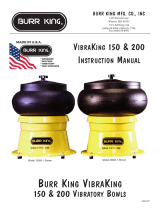
You can also add an articulating
arm to your machine. The arm
simply attaches to the bottom of
the main frame using existing
thread holes.
Fully adjustable and ready for
you to mount your fixtures.
Order part # ARTARM-BBA20

20.51
20.00
9.79
21.61
SIDE VIEW
29.32
7.25
7.75
4X
.39 THRU
FRONT VIEW
BOTTOM VIEW
MOUNTING HOLE
PATTERN
SEPTEMBER 2022
MODEL BBA20 FOOTPRINT
*Footprint
for 98930 shown your machine may vary
Page 15

MODEL BBA20 EXPLODED VIEW
SEPTEMBER 2022
29
28
27
26
30
22 23 2425
32
63
66
46
34
45
40
43
31
65
21
41
42
55
17
36
18
38
39
37
35
44 9 48 41 42 33 56
11531468 5810
605958
21
54
13
58
64
16
48 49 41 50
51
585957
58 34
606566
6766
62
61
67
19
52 12
15
47
69
20
98930 Shown
Page 16

Page 17
MODEL BBA20 PARTS LIST
SEPTEMBER 2022
*
*
*
*
* MAY BE ORDERED AS ASSEMBLY--ORDER P/N 707EX
ITEM NO. PART NUMBER DESCRIPTION QTY.
1 1054 PLATE-BASE 1
2 99-0025 SUPPORT-MOTOR 1
3 150B-1725C MOTOR-1.5 HP 3PH 56C 1
4 908-1 C-FACE ADAPTER 1
5 1026A-1M FRAME ASSEMBLY (BBA20) 1
6 99-0026 BRACKET-SUPPORT 1
7 MB-4C3 BRACKET-CONTROL 1
8 1039-1 BELT- MICRO-V 1
9 725-10 MICRO-V PULLEY 1.62 X 5/8 1
10 730-11 MICRO-V PULY 2.5 X 25MM 1
11 1028-5HRH SPINDLE ASSY. 1
12 1033 MOUNT-BEARING 2
13 1034 SHROUD-BEARING MOUNT 1
14 1034-3 SHROUD-BRG. MT. (BBA20) 1
15 11-0016 BALL BEARING 2
16 10-0003 CIRCLIP 1" OD 1
17 1094 MOUNT-IDLER (ASSY) 1
18 245 GOOSENECK ASSEMBLY 1
19 862-4 CONTROL-VARI-SPEED 1
20 99-0002 KIT-CONDUIT 1
21 246 HANDLE-TRACKING 1
22 707C SHAFT-BEARING 1
23 707EXM WHEEL-IDLER 1
24 701F CIRCLIP 5/8 2
25 701B BEARING-BALL 2
26 2220 WHEEL-CONTACT 20 X 2 1
27 1053 FLANGE-WHEEL 1
28 726 WASHER-WHEEL 1
29 727 NUT-5/8-18 JAM 1
30 BELT BELT-2 X 72 1
31 1095 ARM-TRACKING 1
32 1055 HANDLE-BELT CHANGE 1
33 1035 PLATE-COVER 1
34 253 BRACKET-BELT CHANGE 1
35 6-0017 WASHER-1/2 USS FLAT 1
ITEM NO. PART NUMBER DESCRIPTION QTY.
36 248 SPRING-BELT TENSION 1
37 7-0017 SET SCREW 1/2-13 x 1 CP 1
38 99-0075 SHIM 002-.010 (TO FIT) 1
39 241 PAD-GLIDE 4
40 7-0016 SHCS 3/8-24 x 2 1
41 17 WASHER- 3/8 AN960-616 7
42 39 NUT 3/8-24 NYLOK JAM 3
43 25 SET SCREW 5/16-18 X 3/8 CP 2
44 5-0048 SET SCREW 5/16-18 x 1/4 CP 1
45 1515-1 GROMMET/BUMPER 1
46 7-0012 WASHER-5/16 FENDER 1
47 7-0011 BHSHCS 5/16-18 X 3/4 1
48 42 WASHER-3/8 FLAT GR.8 6
49 5-0014 WASHER- 3/8 INT. STAR 4
50 1-0003 HHCS 3/8-16 X 1 1/4 GR. 5 4
51 920 STUD 3/8 x 1 1/2 DOUBLE 2
52 2-0026 SHCS 1/4-28 x 1 6
53 1-0021 SHCS 1/4-28 x 1 3/4 6
54 2-0027 SHCS 5/16-18 x 2 5
55 3-0020 FHSHCS 3/8-16 x 3/4 5
56 2-0028 BHSHCS 1/4-28 x 1/2 2
57 1-0044 HHCS 5/16-24 x 3/4 GR.8 4
58 4 WASHER-5/16 SAE 20
59 5-0017 WASHER-5/16 SPLIT LOCK 12
60 37 HHCS 5/16-18 X 3/4 GR 5 12
61 5-0032 WASHER-1/4 SPLIT LOCK 4
62 2-0019 BHSHCS 1/4-20 x 5/8 4
63 2-0014 BHSHCS 1/4-20 X 1/2 2
64 4-0014 NUT-5/16-18 NYLOCK GR 8 4
65 209 SHCS 1/4-20 X 3/4 5
66 5 WASHER 1/4 AN960-416 10
67 4-0013 NUT 1/4-20 KEP 4
68 701G-1 KEY 3/16 x 1 7/16 1
69 18 WASHER 5/16 AN960-516 4
*
BOM for 98930 shown your machine may vary
/