Page is loading ...


Page 2
BURR KING MFG. CO., INC
1220 Tamara Lane
Warsaw, MO 65355
www.burrking.com
(660)438-8998 • Fax (660)438-8991
October 2022
LETTER OF AUTHENTICITY
This letter is to certify that all Burr King Belt grinders, Disc grinders,
Polishing machines Vibra King Chambers and Bowls are manufactured
and assembled in the United States of America.
(Tariff number 847990 criterion A)
Don MacCarthy
President

Page 3
BURR KING MFG. CO., INC
1220 Tamara Lane
Warsaw, MO 65355
www.burrking.com
(660)438-8998 • Fax (660)438-8991
October 2022
Burr King Manufacturing Company. Inc. warrants the below product to be free of defects in material and workmanship. The period of
warranty is 1 year (90 days for vibratory bowls of 20 quart and lesser volume) from the date of purchase. No warranty is provided for pro-
ducts that have been modified, abused, handled carelessly, where repairs have been made or attempted by others, or for freight damage. No
warranty is provided for three phase electric motors, controllers, etc. when the motors, controllers are not protected by magnetic starters
that were supplied and installed by Burr King Manufacturing Company. Inc. No other warranty, written or verbal is authorized by Burr
King Manufacturing Company, Inc.
During the warranty period Burr King Manufacturing Company, Inc (or its authorized suppliers or agents) will replace or repair the below product
without charge if the product is found by Burr King Manufacturing Company, Inc. to be defective. To receive warranty services you must contact
Burr King Manufacturing Company, Inc. and receive authorization for warranty service. Unless otherwise authorized by Burr King Manufacturing
Company, Inc. Products (see * below) must be returned to the factory to receive warranty service.
*Motors, speed controllers, and certain other accessories are warranted by their respective manufacture. To receive warranty service on these
items you must contact a brand label service center that supports the product in need of service. Burr King Manufacturing Company; Inc. will assist
you in locating a service center.
For the first thirty days after purchase, and when Burr King Manufacturing Company, Inc. authorizes warranty service, we will pay nor-
mal and necessary surface freight charges both ways (except for items in *). After thirty days the customer is responsible for all freight
charges. Where possible Burr King Manufacturing Company, Inc. may elect to make on site service and/or repairs necessary to return the
product to serviceable condition.
To assure prompt warranty service it is necessary that you complete and return the below warranty information to Burr King Manufacturing Com-
pany, Inc. please FAX, MAIL, email to [email protected] or Submit online at your convenience.
Product model: _______________________ Serial number: _______________________
Date Purchased: ______________________ Purchased from: ______________________
Address: ____________________________ City: _______________________State/Prov: _________Postal code________
Your company name: _____________________________________________
Address: _____________________________City: _______________________State/Prov: __________Postal code________
Phone: _______________________________Fax: _______________________Email: _______________________________
Your name: ___________________________Title: _______________________
How did you learn about Burr King products?
Tradeshow___Web___Industrial Distributor ___Advertisement ___Other __________________________Which one:________________________
What is the intended use of this product? ______________________________________________________________________________________
Please indicate the general work types performed at your company, check all that apply:
Fabrication___Machining___Casting__Molding___Welding___Finishing___Assembly___Research___Other___
Please indicate the primary product focus of your company; check all that apply,
Aircraft/Missile___Automotive___Contract machine___Contract Fabrication___ Agricultural____Maintenance___ Recreational___
Job shop___Foundry___Construction___Arts___Orthopedic___Dental___Medical___Other_________________________________
Please tell us what we can do to improve our products:
________________________________________________________________________________________________________________________
________________________________________________________________________________________________________________________
________________________________________________________________________________________________________________________
May we contact you? Yes___No___
Thank you for purchasing Burr King products!
Register online @
www.burrking.com

Page 4
Important Safety Instructions
OPERATOR, and OPERATING AREA SAFETY
WHEN USING ELECTRIC TOOLS, BASIC SAFETY PRECAUTION SHOULD ALWAYS BE FOLLOWED
TO REDUCE RISK OF FIRE, ELECTRIC SHOCK AND PERSONAL INJURY.
READ AND SAVE ALL INSTRUCTIONS FOR FUTURE REFERENCE
Subject equipment includes Grinders, buffers, polishers, and other rotating equipment. Serious injury or death
may occur if minimum safety precautions are not understood, and obeyed by operators and those other persons
who may be in the immediate vicinity of the subject equipment. Persons who operate, or are in the immediate vi-
cinity of the subject equipment must be properly trained in, and use, minimum safety precautions and procedures
for such machinery.
1. READ ALL INSTRUCTIONS
• Read and understand all operating instruction, manuals, labels, and other information provided with the
equipment.
2. KEEP WORK AREA CLEAN
• Cluttered areas and benches invite injuries.
3. CONSIDER WORK AREA ENVIRONMENT
• Do Not expose power tools to rain
• Do Not use grinder in damp or wet locations.
• Keep work area well lit.
• Do Not use grinder in presence of flammable liquids or gases
4. GUARD AGAINST ELECTRICAL SHOCK
• Prevent body contact with grounded surfaces. For example: pipes, radiators. Disconnect from power source when
not in use. Never u se if electrical cord is damaged or wet. Always keep electrical cords clear of rotating parts and
belt while in motion. Electrical installation shall be in accordance with applicable codes and regulations.
5. KEEP CHILDREN AWAY
• Do Not let visitors contact tool or cord
• All visitors should be kept away from work area
6. DRESS PROPERLY
• Do Not wear loose clothing or jewelry.
• Non-Skid footwear is recommended when working with equipment.
• Wear protective hair coverings to contain long hair.
• Wear proper attire to protect eye, hand, face, arm, leg, feet and body that is adequate to protect against flying
debris, forcibly ejected work pieces, broken abrasive belts, ect.
7. USE SAFETY GLASSES
• Everyday eyewear does not feature impact resistance lenses, and they are NOT safety glasses
8. WEAR DUST MASK
• Some dust created by grinding activities may contain chemicals known to cause cancer, birth defects or other
harm. Provide adequate ventilation.
9. SPARK AND DEBRIS ARRESTING APPARATUS
• To further reduce the exposure you may wish to connect an apparatus to the machine to contain dust and
debris/spark arresting device to suppress sparks thereby limiting human inhalation risk, and risk of fire or explosion
WARNING!

10. KEEP ALL GUARDS IN PLACE AND PROPERLY ADJUSTED
• Keep all guards in place and in working order.
• Do not reach inside the safety guards while the machine is running.
• Do not operate this machine if the gap (nip point) between a moving belt, wheel or disc and the work support
surface exceeds 1/8 inch or 3.175 mm
• Never position the work rest table at an acute angle between the top of the work rest table and the moving belt or
wheel. Doing so will create “nip point” that can cause serious injury should an operators body part become entan
gled (pulled into) the nip point created by this acute angle.
• Do not operate this machine if the gap between the moving abrasive belt, disc or wheel and the adjacent face of
the work rest (or table) will permit passage of the work piece through the gap (nip point). Note, however, that cer
tain alloys such as titanium may create conditions where grinding debris can accumulate in a tight gap creating a
potential fire hazard. When in doubt consult with your safety officer. Failure to observe this warning may result in
the work piece or other item being caught in this gap. And/or being forcibly ejected. Failure to heed this warning
may cause serious bodily harm to the operator and/or bystanders. Never use this equipment if you are not properly
trained in its operation and/or safe use. If in doubt stop and ask for guidance.
11. SECURE THE MACHINE
• Bolt the machine securely to the stand or other stable surface to avoid tipping when unit is in operation. If
mounted on stand make sure the stand is secured to the floor.
12. BEFORE SERVICING
• Disconnect the grinder from the power source.
13. NEVER LEAVE TOOL RUNNING UNATTENDED
• Turn power off. Don’t leave until the grinder comes to a complete stop.
14. DO NOT USE NEAR FLAMMABLE MATERIALS
• Sparks from the grinder can cause fires.
15. HOLD MATERIAL TIGHTLY
• Always hold the work piece firmly when grinding and apply steady pressure.
• Use work piece holding devices when ever possible that diminish the possibility that persons will come in contact
with moving machine pieces, or spark/debris output from the machine.
16. DO NOT USE DAMAGED WHEELS OR ABRASIVES
• Wheels that show wear should be replaced.
17. USE BELTS FROM RESPECTED WHEEL MANUFACTURES
• Not all belts are created equal. Belts that are very inexpensive are usually manufactured cheaply.
18. KNOW WHAT YOUR GRINDING
• Avoid mixing different metals, alloys, and materials. To mix such materials might create a fire or explosion hazard
• Exotic materials such as titanium, magnesium, and other chemically active materials will present fire and explo
sion hazards that if ignored can result in grave personal injury and/or property damage.
• Consult with your material supplier or other qualified expert regarding the materials on which you wish to work.
19. KEEP MACHINE MAINTAINED
• Ensure contact wheels and idler wheels are in good condition and are free from cuts or splits. If damaged parts are
found, immediately discontinue use of the grinder and order replacement parts.
• Never perform maintenance on the grinder with its electrical power source connected.
20. DO NOT USE STONE WHEELS
• The use of stone or vitreous wheels on any Burr King grinder is prohibited. The machine guarding is not suitable
for these types of wheels. To do so will create an operator safety hazard.
All Burr King products are warranted for various time periods to be free of material and/or workmanship defects. Burr
King Manufacturing Companies standard warranty policy is summarized as follows for contact wheels. 1 year from date
of purchase if mounted on a Burr King machine purchased on the same date or 90 days if purchased as a spare or replace-
ment part. Our warranty does not apply to wheels that are mounted on products not manufactured by Burr King Manufac-
turing Company, Inc. Users who mount Burr King manufactured contact wheels on product not manufactured by Burr
Page 5

King Manufacturing Company, Inc. do so at their own risk and assume all liability for having so mounted the contact
wheel(s).
Remember good safety practice demands guarding to protect operators and bystanders from wheel failure and/or debris.
Never use the subject wheel without proper guarding that meets commonly accepted safe practice. See OSHA, U/L, CSA,
CE, ISO and other respected safety standards.
21. OCCUPATIONAL NOISE EXPOSURE
Burr King products produce levels of noise consistent with their intended purposes. The level and spectral
content of noise produced is dependent on the product type, the degree that the product is maintained in proper
operating condition, the abrasive/media and accessories used, the specific application, and the surrounding envi
ronment. Noise levels produced by various Burr King grinders and polishers, as measured at the Burr King fac
tory, range from 80 to 93 decibels. Product operators and persons in the immediate product vicinity should be
protected from excessive noise levels as prescribed in OSHA regulation 29, piece 1910.95 titled “Occupational
Noise Exposure”.
ROTATING EQUIPMENT CAN BE DANGEROUS TO OPERATORS AND THOSE WHO MAY BE IN ITS
IMMEDIATE OPERATING VICINITY. IT IS THE ABSOLUTE AND DIRECT RESPONSIBILITY OF PUR-
CHASERS, MANAGERS, AND OPERATORS OF THIS EQUIPMENT TO UNDERSTAND AND OBEY THE
FOREGOING MINIMUM OPERATING SAFETY REQUIREMENTS. IF YOU HAVE QUESTIONS OR
SAFETY CONCERNS REGARDING OPERATING THE SUBJECT EQUIPMENT PLEASE CALL YOUR AU-
THORIZED BURR KING DISTRIBUTOR, OR BURR KING MANUFACTURING AT 660-438-8998. YOUR
SAFETY IS OUR FOREMOST CONCERN!
Burr King Manufacturing disclaims any and all responsibility for injuries, damage, loss of income, or other adverse
consequence as might be incurred by purchasers, managers, and operators of this equipment.
22. TRAINING
• Do train operators and others in safe operating practices
• Post these instructions so they are available for future reference and new operators.
23. ROTATIONAL SPEED WARNING, CONTACT WHEELS
Scope: Contact wheels manufactured by Burr King Manufacturing Company, Inc., which have rubber or urethane
tires. Examples include but are not limited to stock codes 202, 302, 402, 502,702, 802, 902, 1002, 1202, 2220 and
variants. Variants have stock codes that begin with the base number; i.e. 802-S-55 is an 802 variant.
Users are warned not to exceed the below listed revolutions per minute (RPM) on the subject wheels. Failure to
heed this warning may lead to tire de-bonding, fragmentation, or other mechanical failure. Such failures may
cause serious personal injury to operators or bystanders, and/or cause property damage. All Burr King products
are warranted for various time periods to be free of material and/or workmanship defects. Burr King Manufactur-
ing Companies standard warranty policy is summarized as follows for contact wheels. 1 year from date of pur-
chase if mounted on a Burr King machine purchased on the same date or 90 days if purchased as a spare or
replacement part. Our warranty does not apply to wheels that are mounted on products not manufactured by Burr
King Manufacturing Company, Inc. Users who mount Burr King manufactured contact wheels on product not
manufactured by Burr King Manufacturing Company, Inc. do so at their own risk and assume all liability for hav-
ing so mounted the contact wheel(s).
Remember good safety practice demands guarding to protect operators and bystanders from wheel failure and/or
debris. Never use the subject contact wheels without proper guarding that meets commonly accepted safe practice.
See OSHA, U/L, CSA, CE, ISO and other respected safety standards.
Stock code
Contact Wheel Maximum Safe RPM
202, 302 10000
402, 502, 702 802 4400
902, 1002 3000
1202 2200
2220 150
Page 6

Page 7
BURR KING MFG. CO., INC
1220 Tamara Lane
Warsaw, MO 65355
www.burrking.com
(660)438-8998 • Fax (660)438-8991
Mounting Instructions for
14xx series internal grinding attachments
14xx internal grinding attachments provide valuable functional additions to Burr King belt grinders such as:
• extension of the belt track outward approximately 6 inches
• small diameter nose wheels for tight radii grinding
• belt tracks from ½ inch wide up to the standard belt track width of the machine
• close access to corners, radii, cavities, tubes and other part features that may be otherwise inaccessible
• reduced belt speeds for better grinding characteristics on many materials
• flexibility to mount many different Burr King nose extensions on the base attachment
• belt track and tension control via the mounted machine functions.
14xx internal grinding attachments may be mounted on the Burr King Model 760. The belt length required for each ma-
chine is increased by 12 inches from standard when the 14xx attachment is mounted on the machine. In example, the belt
length for the model 760 is increased from 60 to 72 inches. Additionally, mounting 14xx attachment results in a reduction
of belt speed to approximately 42% of the pre-mount speed. In example, mounting a 14xx attachment on a model 760 nor-
mally operating at 8000 surface feet per minute (SFPM) reduces the belt speed to approximately 3360 SFPM. If you re-
quire faster belt speed ask Burr King for the optional 4-inch diameter drive wheel. Drive wheel (P/N 412) will increase
belt speed to approximately 125% of that provided by the standard 3-inch diameter drive wheel (P/N 302).
Mounting a 14xx attachment on a Burr King belt grinder requires the removal of the machine’s standard contact wheel,
contact wheel guard, work rest and work rest support arm, back-up platen and platen support assembly. Correctly install-
ing the 14xx attachment provides for pinch point protection and other safety features otherwise provided by the standard
machine items removed.
Caution: Failure to mount the 14xx properly may create a safety hazard. Observe the safety instructions attached
and those provided with the mounted machine.
-----------------------------------------------------------------------------------------------------------------
Mounting a 14xx attachment:
Locate the parts list for the machine on which you wish to mount the 14xx. For purposes of this instruction the Burr King
model 760 belt grinder is used for explanation. Do not discard any part that you remove from the grinder as it will be re-
quire should you desire to return the machine to its standard configuration.
1. Disconnect the machine from its main power source. Assure that no one is able to turn the power back on
without your approval.
2. Slack the abrasive belt and remove it from the machine.
3. Clean the machine thoroughly (it’s just a good time to do it!).
4. Remove contact wheel retaining nut and washer (P/N 727 and 726).
5. Remove the contact wheel (P/N 702).
6. Loosen the contact wheel clamping screw (P/N 10).
7. Remove the contact wheel guard and platen assembly (P/N 703, 704b, 704a and hardware).
8. Loosen the work support clamping screw (P/N 10).
9. Remove the work support arm and work support
10. Carefully clean and lightly oil the outer diameter of the contact wheel bearing assembly (P/N 701).
11. Assure the clamping screws of the mounting bracket (P/N 1425) are loose then slide the support arm over the
contact wheel bearing assembly until it stops.
12. Position the mounting bracket approximately horizontal and tighten the clamping screws.
13. Install the small drive wheel (P/N 302) on the 5/8 inch contact wheel arbor and secure it using the flange washer
(P/N 1426) and the original contact wheel nut (P/N 727), tighten securely.

Page 8
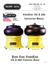
14. Install the belt style of your choice (must be 12 inches longer than the standard belt) as follows:
a . route the belt according to figure 1.
b. assure the belt is routed such that the red pinch guards (P/N 1429) protect the pinch points (see figure 1)
c. tension the belt using the rear wheel handle assembly.
Other 14xx installation instructions:
It may be necessary to adjust the position, angle, or extension length of the 14xx arm assembly. This may be necessary be-
cause of the belt you chose, the condition of your machine, or the angle that you wish the arm to be at. Do this by:
1. loosening two set screws (P/N 1445) that secure the main pivot bar (P/N 1426) to the mounting bracket (P/N 1425)
2. rotate the forward portion of the 14xx until it is in a position suitable for your work and, such that the abrasive belt
can be tensioned. Note: It may be necessary to position the pivot bar (see step 12 above)
3. securely tighten the two set crews (P/N 1445) to fix the position of the forward portion of the 14xx attachment.
Tracking the abrasive belt on the nose wheel is done by using the standard belt-tracking knob of the left side of the
mounted machine. Note: The ½-inch wide small diameter extensions (P/N 1438/1439) has an additional tracking adjust-
ment located on the left side of P/N 1438. Rotate the adjusting screw CW or CCW as required to make small tracking ad-
justments on this assembly. Usually once this adjustment is performed it is not often again required.
Tips for obtaining the best service from your 14xx attachment
1. Use good quality abrasive belts.
2. Whenever possible use pliant, flex back belts. Doing so will help in blending, particularly in tight radii, cavities, etc.
3. Use the nose wheel whenever possible as the preferred grinding site.
4. Maintain sufficient but not extreme abrasive belt tension. Normally the mounted machine rear wheel arm should be
pushed back about 4 ratchet clicks past initial belt contact. Note: belts of different composition behave differently,
i.e. a nylon belt will tend to stretch more than a cloth backed belt.
5. When using thick belts such as nylon web types it may be necessary to adjust the pinch guards for sufficient but not
excessive clearance. CAUTION: There should be no more than 1/8 inch clearance between the moving belt (or
wheel) surface and the pinch guard.
6. Assure that the 14xx idlers (P/N 1444) remain serviceable. The idler wheels are made of very tough urethane (or
steel optional) and will provide good service life. They will, however, wear progressively. If they wear to the point
that they are severely coned, tapered, out of round, or simply too small they need to be replaced. Continued use of
badly worn idlers will result in excessive wear to the mounted machine's wheels since the mounted machine will
override the worn idlers and wear excessively.
7. Small diameter nose wheels turn at high revolutions per minute (RPM). In example, a 9/16-inch wheel will revolve
at over 20000 RPM. The nose wheel bearings at designed to operate at this speed, however, applying high radial or
axial loads to the nose wheel will shorten its service life. In general, keep applied force below 5 pounds for very
small wheels. Larger wheels have larger bearings, turn slower and will tolerate higher applied loads.
8. Where heavier grinding is desired use harder and/or serrated nose wheels. Burr King can help you with the best
wheel selection. Burr King can supply nose wheels from 3/8 inch to 3 inches in diameter and from 1.2 to 2 inches
wide. Nose wheels require the use of the proper support extension.
9. Use different front extensions for access to close corners, cavities, or special grinding needs. Burr King can help
you select the best front section for your 14xx attachment.
10. Maintain the 14xx attachment, and the mounted machine in clean, serviceable condition. Assure all pinch guards,
and other guards on the attachment and mounted machine are serviceable and used.
Burr King Manufacturing will help you with all of your finishing needs. If you have an application problem, or need other
assistance please contact us at any of the indicated phone numbers or at WWW.burrking.com . Thank you for choosing
Burr King products!
Figure 1: SAFETY GUARD SHOWN OPEN FOR CLARITY. DO NOT OPERATE WITH SAFETY GUARD OPEN


2-0011
5
1425
302
1456
30
1426
1427
1428
1445
1429
1445
1437
1429
5
1431
1431
1430
1444
727
1438
1435
1441
1439
1432
1434
1436
30
5
1422
OPTIONAL WHEEL SIZES
SEE REVERSAL FOR
(INCLUDED WITH 1400)
(INCLUDED WITH 1402)
WHEEL
OPTIONS
Fork Style Kits
1401 (1x72) Fork Style Small Wheel Attachment
1402 (2x72) Fork Style Small Wheel Attachment
1403 (2x72) Outboard Bearing Small Wheel Attachment
Uni-ArmStyle Kits Access Kits
1401U (1x72) Uni-Arm Small Wheel Attachment
1442
1443
5
30
WHEEL
OPTIONS
5
1443
OPTIONAL WHEEL SIZES
SEE REVERSAL FOR
(INCLUDED WITH 1401)
1443
OPTIONAL WHEEL SIZES
SEE REVERSAL FOR
5
99-0043

1452
1453
1451
WHEEL
OPTIONS
WHEEL
OPTIONS
WHEEL
OPTIONS
WHEEL
OPTIONS
3" DIA ARMS
1452
BY2322
BD2322
BD2312
1498-5
1453
10-0002
AV2311
AV2321
1451 ARM-CONTACT WHEEL w/AK1311
AL1311 URETHANE CONTACT WHEEL 9/16x1
AN1311 URETHANE CONTACT WHEEL 3/4x1
AK1311 URETHANE CONTACT WHEEL 1x1
AE1311 URETHANE CONTACT WHEEL 1 1/2x1
AL1312 RUBBER CONTACT WHEEL 9/16x1
AN1312 RUBBER CONTACT WHEEL 3/4x1
AK1312 RUBBER CONTACT WHEEL 1x1
AE1312 RUBBER CONTACT WHEEL 1 1/2x1
2" ARM PARTS
ARM-CONTACT WHEEL w/BD2322
CONTACT WHEEL 3x1/2
CONTACT WHEEL SERRATED 3x1
CONTACT WHEEL 3x1
1400 SERIES ATTACHMENTS USE
1400 SERIES COMMON PARTS
DESCRIPTIONP/N QTY
5
30
2-0011
302
202B
1425
1426
1427
1428
1429
1430
1431
30
1437
1444
1445
1456
1432
1434
1435
1438
1439
1441
DA2212
DB2003
DA2003
DC2212
1436
1442
AL2311
AN2311
AK2311
AE2311
WASHER AN916-416
SCREW-ALLEN CAP 1/4-20 x 1
SCREW-ALLEN CAP 1/4-20 x 1 1/2
DRIVE WHEEL 3" DIA
IDLER WHEEL BEARING
MOUNTING BRACKET
PIVOT BAR
ARM SUPPORT
IDLER WHEEL BACKET
PINCH GAURD
SCREW-ALLEN CAP 5/16-18 x 1
SCREW-ALLEN CAP 1/4-20 x 1/2
SCREW-ALLEN CAP 1/4-20 x 3/4
ROLL PIN 1/8 x 3/8
IDLER WHEEL
SET SCREW 1/4-20 x 5/8
5/8 WASHER-DRIVE WHEEL
ARBOR PIN .1245
BEARING - 1/8 x 1/4
SCREW-ALLEN CAP 1/4-28 x 3/4
CONTACT ARM SUPPORT
ARM-CONTACT WHEEL 3/8" & 1/2"
SET SCREW 1/4-28 x 1/2
CONTACT WHEEL RUBBER 7/16 x 3/8 DIA
CONTACT WHEEL STEEL 5/16 x 3/8 DIA
CONTACT WHEEL STEEL 7/16 x 3/8 DIA
CONTACT WHEEL RUBBER 5/8 x 3/8 DIA
BUSHING 9/16 & 3/4 WHEELS ONLY
ARM-CONTACT WHEEL w/ AK2311
CONTACT WHEEL URETHANE 1 1/2 DIA
CONTACT WHEEL URETHANE 1 DIA
CONTACT WHEEL URETHANE 3/4 DIA
CONTACT WHEEL URETHANE 9/16 DIA
8
2
2
1
2
1
1
1
1
3
1
2
2
2
2
4
1
727 NUT, HEX, 5/8-18, JAM 1
1
1
2
1
1
1
1
1
1
1
2
1
1
1
1
1
1400 1/2" PARTS
ARBOR SHAFT
ARM-CONTACT WHEEL w/AV2321
CIR-CLIP
CONTACT WHEEL 2x1
CONTACT WHEEL SERRATED 2x1
COMMON PARTS LISTED BELOW
NON-COMMON OR SPECIFIC BY PART NO.
1401 1" PARTS
1403 2" PARTS
UNI-ARM PARTS
OUTBOARD BEARING ARM PARTS
1459 ARM-CONTACT WHEEL
11-0007 BEARING
OB250 STEEL CONTACT WHEEL 1/4x2
OB500 RUBBER CONTACT WHEEL 1/2x2
OB375 RUBBER CONTACT WHEEL 3/8x2
OB500 RUBBER CONTACT WHEEL 1/2x2
OB562 RUBBER CONTACT WHEEL 9/16x2
OB625 RUBBER CONTACT WHEEL 5/8x2
OB750 RUBBER CONTACT WHEEL 3/4x2
OB1000 RUBBER CONTACT WHEEL 1x2
OB2000 RUBBER CONTACT WHEEL 2x2
AL2312
AN2312
AK2312
AE2312 CONTACT WHEEL RUBBER 1-1/2 DIA
CONTACT WHEEL RUBBER 1 DIA
CONTACT WHEEL RUBBER 3/4 DIA
CONTACT WHEEL RUBBER 9/16 DIA 1
1
1
1
1
1
1
1
1
1
1
1
1
1459 ARM-CONTACT WHEEL COMPLETE
9660 OUTBOARD BEARING NOSE
1455 ARM ADAPTER
11-0007 BEARING
OB250 STEEL CONTACT WHEEL 1/4x2
OB500 RUBBER CONTACT WHEEL 1/2x2
OB375 RUBBER CONTACT WHEEL 3/8x2
OB500 RUBBER CONTACT WHEEL 1/2x2
OB562 RUBBER CONTACT WHEEL 9/16x2
OB625 RUBBER CONTACT WHEEL 5/8x2
OB750 RUBBER CONTACT WHEEL 3/4x2
OB1000 RUBBER CONTACT WHEEL 1x2
OB2000 RUBBER CONTACT WHEEL 2x2
99-0043 O-RING 1
! WHEELS
1459
! WHEELS
1436
1443
AP2311
AO2311
AR2311
AQ2311
ARM-CONTACT WHEEL w/ AR2311
BUSHING 9/16 & 3/4 WHEELS ONLY
CONTACT WHEEL URETHANE 1-1/2 DIA
CONTACT WHEEL URETHANE 1 DIA
CONTACT WHEEL URETHANE 3/4 DIA
CONTACT WHEEL URETHANE 9/16 DIA
1
1
1
1
AP2312
AO2312
AR2312
AQ2312 CONTACT WHEEL RUBBER 1-1/2 DIA
CONTACT WHEEL RUBBER 1 DIA
CONTACT WHEEL RUBBER 3/4 DIA
CONTACT WHEEL RUBBER 9/16 DIA
1
1
1
1
2
1
1402 2" PARTS
! WHEELS ! WHEELS

2-0011
5
1425
302
1456
30
1426
1427
1428
1445
1429
1445
1437
1429
5
1431
1431
30
1447
1448
(INCLUDED WITH 1412
WITH AH5311)
(INCLUDED WITH 1411
WITH AJ5311)
SEE REVERSAL FOR
OPTIONAL WHEEL SIZES
SEE REVERSAL FOR
OPTIONAL WHEEL SIZES
1430
5
30
1473
1444
727
1470
1490 1471 - 9/16 & 3/4 DIA WHEELS
1472 - 1 & 1 1/2 DIA WHEELS
1473
1438
1435
1441
1439
1432
1434
1471 - 9/16 & 3/4 DIA WHEELS
1472 - 1 & 1 1/2 DIA WHEELS
5
30
5
1422
OPTIONAL WHEEL SIZES
SEE REVERSAL FOR
(INCLUDED WITH 1400)
Full/Close Access Kits
1400 (1/2x72) Full Access Small Wheel Attachment
1411 (1x72) Full Acess Small Wheel Attachment
1412 (2x72) Full Access Small Wheel Attachment
5
99-0043

14XX SERIES ATTACHMENTS USE
1400 SERIES COMMON PARTS
DESCRIPTIONP/N QTY
5
30
2-0011
302
202B
1425
1426
1427
1428
1429
1430
1431
30
1437
1444
1445
1456
WASHER AN916-416
SCREW-ALLEN CAP 1/4-20 x 1
SCREW-ALLEN CAP 1/4-20 x 1 1/2
DRIVE WHEEL 3" DIA
IDLER WHEEL BEARING
MOUNTING BRACKET
PIVOT BAR
ARM SUPPORT
IDLER WHEEL BACKET
PINCH GAURD
SCREW-ALLEN CAP 5/16-18 x 1
SCREW-ALLEN CAP 1/4-20 x 1/2
SCREW-ALLEN CAP 1/4-20 x 3/4
ROLL PIN 1/8 x 3/8
IDLER WHEEL
SET SCREW 1/4-20 x 5/8
5/8 WASHER-DRIVE WHEEL
8
2
2
1
2
1
1
1
1
3
1
2
2
2
2
4
1
727 NUT, HEX, 5/8-18, JAM 1
COMMON PARTS LISTED BELOW
1432
1434
1435
1438
1439
1441
DA2212
DB2003
DA2003
DC2212
ARBOR PIN .1245
BEARING - 1/8 x 1/4
SCREW-ALLEN CAP 1/4-28 x 3/4
CONTACT ARM SUPPORT
ARM-CONTACT WHEEL 3/8" & 1/2"
SET SCREW 1/4-28 x 1/2
CONTACT WHEEL RUBBER 7/16 x 3/8 DIA
CONTACT WHEEL STEEL 5/16 x 3/8 DIA
CONTACT WHEEL STEEL 7/16 x 3/8 DIA
CONTACT WHEEL RUBBER 5/8 x 3/8 DIA
1
1
2
1
1
1
1
1
1
1
1422 ASSEMBLY FOR 1400 ATTACHMENT
99-0043 O-RING 1
! WHEELS
* REQUIRES 1472 SIDE RAILS
* REQUIRES 1472 SIDE RAILS
! WHEELS
1470 ASSEMBLY FOR 1411 ATTACHMENT
5 WASHER AN916-416
1433 SCREW-ALLEN CAP 1/4-20 x 3/4 1
1447 ARM-CONTACT WHEEL w/AJ5311 1
1471 RAIL SIDE FOR 9/16 & 3/4 DIA 2
1472 RAIL SIDE FOR 1 & 1 1/2 DIA 2
AA5312 NEOPRENE CONTACT WHEEL 5/6 (.83) x 9/16 1
AB5312 NEOPRENE CONTACT WHEEL 5/6 x 3/4 1
AJ5311 URETHANE CONTACT WHEEL 5/6 x 1* 1
AD5312 NEOPRENE CONTACT WHEEL 5/6 x 1-1/2* 1
! WHEELS
1490 ASSEMBLY FOR 1412 ATTACHMENT
5 WASHER AN916-416
1433 SCREW-ALLEN CAP 1/4-20 x 3/4 1
1448 ARM-CONTACT WHEEL w/AH5311 1
1471 RAIL SIDE FOR 9/16 & 3/4 DIA 2
1472 RAIL SIDE FOR 1 & 1 1/2 DIA 2
AG5312 NEOPRENE CONTACT WHEEL 1-5/16 x 9/16 1
AF5312 NEOPRENE CONTACT WHEEL 1-5/16 x 3/4 1
AH5311 URETHANE CONTACT WHEEL 1-5/16 x 1* 1
AC5312 NEOPRENE CONTACT WHEEL 1-5/16 x 1-1/2* 1
1400
1412
1411
/