Page is loading ...

CCN 99828618
OPERATOR’S MANUAL SB30X-XXX-X
INCLUDING: OPERATION, INSTALLATION & MAINTENANCE
RELEASED: 2-18-00
REVISED: 5-27-10
(REV. G)
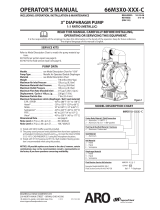
3" SHOCK BLOCKER®
METALLIC PULSATION DAMPENER
READ THIS MANUAL CAREFULLY BEFORE INSTALLING,
OPERATING OR SERVICING THIS EQUIPMENT.
It is the responsibility of the employer to place this information in the hands of the operator. Keep for future reference.
SERVICE KITS
Refer to the Model Description Chart to match the pump material
options.
637330-3X for repair of the diaphragms and “O” rings (see page 4).
PUMP DATA
Models . . . . . . . . . . . . . . . . . see Model Description Chart for “-XXX-X”
Pulsation Dampener Type . . . . . . . . . . . . . Metallic
Material . . . . . . . . . . . . . . . . . . . . . . . . . . . . . see Model Description Chart
Weight . . . . SB30X-XAX-X . . . . . . . . . . . . . . 41 lbs (18.6 kgs)
SB30X-XCX-X . . . . . . . . . . . . . . 94 lbs (42.6 kgs)
SB30X-XSX-X . . . . . . . . . . . . . . . 96 lbs (43.5 kgs)
Material Inlet / Outlet
SB30X-AXX-X . . . . . . . . . . . . . . 3 - 8 N.P.T.F. - 1
SB30X-BXX-X . . . . . . . . . . . . . . Rp 3 (3 - 11 BSP parallel)
Air Inlet (female) . . . . . . . . . . . . . . . . . . . . . . . 3/4 - 14 N.P.T.
Maximum Air Inlet Pressure . . . . . . . . . . . 120 p.s.i.g. (8.3 bar)
Maximum Material Inlet Pressure . . . . . . 120 p.s.i.g. (8.3 bar)
Maximum Temperature Limits (diaphragm / seal material)
E.P.R. / EPDM . . . . . . . . . . . . . . . . . . . . -60° to 280° F (-51° to 138° C)
Nitrile . . . . . . . . . . . . . . . . . . . . . . . . . . . 10° to 180° F (-12° to 82° C)
Santoprene® . . . . . . . . . . . . . . . . . . . . -40° to 225° F (-40° to 107° C)
PTFE . . . . . . . . . . . . . . . . . . . . . . . . . . . . 40° to 225° F (4° to 107° C)
Viton® . . . . . . . . . . . . . . . . . . . . . . . . . . . -40° to 350° F (-40° to 177° C)
Maximum Fluid Volume . . . . . . . . . . . . . . . 367 in. (6.01 lit.)
Dimensional Data . . . . . . . . . . . . . . . . . . . . . . see page 7
NOTICE: All possible options are shown in the chart, however, certain
combinations may not be recommended, consult a representative or
the factory if you have questions concerning availability.
MODEL DESCRIPTION CHART
SB30 X - X X X - X
Air Section Material
A - Aluminum
S - Stainless Steel
Fluid Connection
A - 3 - 8 N.P.T.F. - 1
B - Rp 3 (3 - 11 BSP, parallel)
Fluid Section Service Kit Selection
EXAMPLE: Model #SB30A-BAP-G
Fluid Section Service Kit # 637330-3G
SB30X - XXX - X
Diaphragm
637330 - 3 X
Fluid Cap Material
A - Aluminum
C - Cast Iron
S - Stainless Steel
Diaphragm Material
A - Santoprene
G - Nitrile
T - PTFE / Santoprene
V - Viton
Hardware Material
P - Carbon Steel
S - Stainless Steel
Figure 1
INGERSOLL RAND COMPANY LTD
209 NORTH MAIN STREET – BRYAN, OHIO 43506
(800) 495-0276 FAX(800) 892-6276
© 2010
www.ingersollrandproducts.com

Page 2 of 8 SB30X-XXX-X (en)
WARNING
EXPLOSION HAZARD. Do not exceed maximum
uid inlet pressure of 120 p.s.i. (8.3 bar). Operating at higher
pressure can cause explosion, resulting in property damage or
severe injury.
WARNING
USE ONLY WITH COMPRESSED AIR. Do not use
bottled gas products to run the pulsation dampener. Un-
regulated high pressure bottled gas has the potential for over-
pressurization. Certain gasses, such as Nitrogen, can cause un-
predictable results. The pressure source MUST BE REGULATED.
WARNING
CHEMICAL COMPATIBILITY HAZARD. Do not
use with certain fluids. Incompatible fluids may attack and
weaken the housing, causing rupture or explosion, which can
result in property damage or severe injury. See manufacturer’s
information on uid compatibility.
WARNING
DISASSEMBLY HAZARD. Do not disassemble this
unit when it is under pressure. Relieve all material pressure in
the pumping system before attempting service or disassembly.
Disconnect air lines and carefully bleed any pressure off the
system. Be certain the system is not maintaining pressure due
to a material restriction in the hose, line, dispensing device
or the spray or extrusion tip. Failure to relieve pressure, both
upstream and downstream, may result in an injury upon disas-
sembly.
OPERATING AND SAFETY PRECAUTIONS
READ, UNDERSTAND AND FOLLOW THIS INFORMATION TO AVOID INJURY AND PROPERTY DAMAGE.
CAUTION
AIR MUST BE SUPPLIED TO THE SHOCK BLOCKER
BEFORE APPLYING FLUID PRESSURE. Failure to pressurize
with air rst can damage the diaphragm.
CAUTION
ALWAYS RELIEVE THE FLUID PRESSURE BEFORE
REMOVING THE AIR PRESSURE. Failure to relieve uid pres-
sure can damage the diaphragm.
CAUTION
NOT FOR STRUCTURAL SUPPORT. Do not use
this product to support other system components or use
as a step. Improper support can result in fracture of the hous-
ing, causing damage. Plumbing must be supported to prevent
stresses upon it.
NOTICE
Replacement warning labels are available upon
request: “Static Spark & Diaphragm Rupture” pn \ 94080.
WARNING
= Hazards or unsafe practices which
could result in severe personal injury,
death or substantial property damage.
CAUTION
= Hazards or unsafe practices which
could result in minor personal injury,
product or property damage.
NOTICE
= Important installation, operation or
maintenance information.
OPERATING INSTRUCTIONS
WARNING
HEED WARNINGS AS SHOWN IN “OPERATING
AND SAFETY PRECAUTIONS” ABOVE.
AIR REQUIREMENTS
Supply the unit with clean, dry air.
A lter capable of ltering out particles larger than 50 microns
should be used on the air supply.
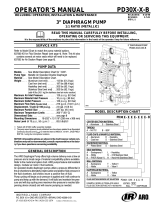
INSTALLATION INSTRUCTIONS
Position the shock blocker pulsation dampener as close to the
y
y
y
pump discharge as possible (as shown in gure 2).
CAUTION
SUPPORT THE PIPE IMMEDIATELY DOWNSTREAM
FROM THE SHOCK BLOCKER. Support is required to eliminate
forces and moments from the shock blocker anges and pump
manifold. Cantilever support is suggested immediately down-
stream from the shock blocker.
Use a tee connector after the F-R-L on the pump air supply line
and connect the line to the shock blocker’s valve body (1/4”
i.d. hose is su cient). When the air supply to the pump is shut
down, the air to the shock blocker will be shut down as well.
y
TYPICAL SYSTEM INSTALLATION
Filter
Regulator
Lubricator
Shut-o
Valve
Check
Valve
Shut-o
Valve
Back
Pressure
Gauge
(optional)
Discharge
Suction
Support required.
(see “Installation Instructions”)
Figure 2

SB30X-XXX-X (en) Page 3 of 8
y
Viton® is registered trademarks of the DuPont Company
y
Santoprene® is a registered trademark of Monsanto Company, licensed to Advanced Elastomer Systems, L.P.
y
y
Lubriplate® is a registered trademark of Lubriplate Division (Fiske Brothers Re ning Company)
y
ARO® and Shock Blocker® are registered trademarks of Ingersoll-Rand Company
y
GENERAL DESCRIPTION
The ARO® shock blocker pulsation dampener is designed to work
with 1:1 ratio pumps having an outlet pressure not exceeding 120
p.s.i. (8.3 bar). The shock blocker will effectively reduce material
pressure variations, surges and shock to piping and delivery in uid
systems during pump reversal. It can significantly contribute to
pulse reduction in low pressure spray applications.
Accurate selection of wetted material will assure longest service life
and minimize down time. Several material options are available for
the body and diaphragm materials. Fluid section materials avail-
able include: aluminum, cast iron and stainless steel. For specific
uid compatibility, consult the chemical manufacturer.
The shock blocker uses a single air pressurized, exible diaphragm
working against the uid line pressure. Several diaphragm material
options are available to allow custom matching to the uid mate-
rial for best compatibility (refer to the model description chart).
Shock blocker units can also be added in series to provide addi-
tional dampening on the material.
Pressure relief through the exhaust port is a normal compensating
function of the control valve in the shock blocker. It will automati-
cally adjust itself to the required operating pressure once the mate-
rial pressure has been applied. The pressure supplied to the shock
blocker needs to be equal to the material pressure to provide the
proper dampening e ect.
AIR AND LUBE REQUIREMENTS
WARNING
EXCESSIVE AIR PRESSURE. Can cause pulsation
dampener damage, personal injury or property damage.
A lter capable of ltering out particles larger than 50 microns
should be used on the air supply. There is no lubrication re-
quired other than the “O” ring lubricant which is applied during
assembly or repair.
If lubricated air is present, make sure that it is compatible with
the “O” rings and seals in the air motor section of the pump.
OPERATION
CAUTION
DO NOT EXCEED 120 P.S.I. (8.3 BAR). Operating
at higher pressure can cause explosion, resulting in property
damage or severe injury.
Pressure relief through the exhaust port is a normal compen-
sating function of the control valve in the shock blocker. It will
automatically adjust itself to the required operating pressure
once the material pressure has been applied.
Operate the system for a few minutes to equalize air and uid
chambers of the pulsation dampener.
PARTS AND SERVICE KITS
Refer to the part views and descriptions as provided on pages 4
and 5 for parts identi cation and Service Kit information.
Certain ARO “Smart Parts” are indicated which should be avail-
able for fast repair and reduction of down time.
MAINTENANCE
Provide a clean work surface to protect sensitive internal mov-
ing parts from contamination from dirt and foreign matter dur-
ing service disassembly and reassembly.
Keep good records of service activity and include pump in pre-
ventive maintenance program.
Before disassembling, empty captured material in the uid cap
by tipping the pulsation dampener on end.
y
y
y
y
y
y
y
y
FLUID SECTION DISASSEMBLY
Remove (107) reducing bushing.
Remove six (26) screws, releasing two (4) anges and (11) “O”
rings.
Remove eight (27) screws and (29) nuts, releasing (15) uid cap.
Secure (14) screw in a vise, with (101) air valve body upward.
Using a 15/16” socket on (186) screw, unthread and remove
(186) screw and (10) washer.
Remove (68) air cap from (7) diaphragm and components.
Remove (14) screw from the vise. Unthread and remove (1) rod,
releasing (2) stopper, (5) back-up washer, (196) cushion, (7) or (7
and 8) diaphragms, (6) washer, (3) “O” ring and (9) washer from
(14) screw.
Remove four (131) screws, releasing (101) air valve body from
the (68) air cap.
Remove (144) “U” cup from (68) air cap.
Remove (103) sleeve from (101) air valve body.
FLUID SECTION REASSEMBLY
Clean and inspect all parts. Replace worn or damaged parts
with new parts as required. Lubricate all replacement parts and
metallic moving parts with Lubriplate® FML-2 grease upon re-
assembly.
Grease and assemble two (172) “O” rings to (103) sleeve.
Assemble (103) sleeve into the (101) air valve body.
Grease and assemble (70 and 173) “O” rings to (101) air valve
body.
Grease and assemble (144) “U” cup into (68) air cap.
Assemble (101) air valve body to (68) air cap.
Assemble four (131) screws, securing (68) air cap. NOTE: Tighten
(131) screws to 20 - 30 ft lbs (27.1 - 40.7 Nm).
Assemble (9) washer, (3) “O” ring, (6) washer, (7) or (7 and 8)
diaphragms, (196) cushion, (5) back-up washer and (2) stopper
to (14) screw. NOTE: For models with PTFE diaphragms: Item
(8) Santoprene diaphragm is installed with the side marked
“AIR SIDE” towards the pump center body. Install the PTFE dia-
phragm (7) with the side marked “FLUID SIDE” towards the (15)
uid cap.
Assemble (1) rod to (14) screw.
Grease and assemble two (173) “O” rings to (1) rod.
Place this assembly into (68) air cap.
Assemble (10) washer and (186) screw into (101) air valve body
and thread into (1) rod. Clamp (14) screw in a vise, with (186)
screw upward, and tighten (186) screw to 65 - 70 ft lbs (88.1 -
94.9 Nm).
Remove assembly from the vise and assemble to (15) uid cap,
securing with eight (27) screws and (29) nuts. NOTE: Tighten (27)
screws to 60 - 70 ft lbs (81.3 - 94.9 Nm).
Grease and assemble two (11) “O” rings to two (4) anges.
Assemble two (4) anges to (15) uid cap, securing with six (26)
screws. NOTE: Tighten (26) screws to 60 - 70 ft lbs (81.3 - 94.9
Nm).
Apply Lubriplate FML-2 grease to threads of (101) air valve
body. Apply PTFE tape to threads of (107) reducing bushing
and assemble to (101) air valve body.
1.
2.
3.
4.
5.
6.
7.
8.
9.
10.
y
1.
2.
3.
4.
5.
6.
7.
8.
9.
10.
11.
12.
13.
14.
15.

Page 4 of 8 SB30X-XXX-X (en)
PARTS LIST / SB30X-XXX-X
Indicates parts included in 637330-3X service kit. Service kit also includes 94276 Lubriplate FML-2 grease packet.
MATERIAL CODE
[A] = Aluminum
[B] = Nitrile
[Br] = Brass
[Bz] = Bronze
[C] = Carbon Steel
[CI] = Cast Iron
[Co] = Copper
[D] = Acetal
[E] = E.P.R.
[I] = Iron
[Sp] = Santoprene
[SS] = Stainless Steel
[T] = PTFE
[V] = Viton
COMMON PARTS
Item Description
(size)
Qty Part No. [Mtl]
1 Rod (1) 94941 [C]
2 Stopper (1) 94837 [D]
3 “O” Ring
(1/8” x 1” o.d.)
(1) Y328-210 [T]
6 Washer (1) 94942 [SS]
9 Washer
(13/16” i.d. x 2” o.d.)
(1) Y13-12-T [SS]
10 Washer
(0.630” i.d. x 1.687” o.d.)
(1) 93065 [SS]
14 Screw
(3/4” - 16 x 2-1/2”)
(1) Y5-131-T [SS]
19 Screw, Self-Tapping
(1/4” - 20 x 1/2”)
(1) Y254-178-Z [C]
43 Ground Lug (1) 93004 [Co]
Item Description
(size)
Qty Part No. [Mtl]
70 “O” Ring
(3/32” x 5/8” o.d.)
(4) Y325-111 [B]
103 Sleeve (1) 94836 [Bz]
131 Screw
(M10 x 1.5 - 6g x 30 mm)
(4) 94845 [C]
144 “U” Cup
(3/16” x 1-3/8” o.d.)
(1) Y186-51 [B]
172 “O” Ring
(1/16” x 1-1/4” o.d.)
(2) Y325-24 [B]
173 “O” Ring
(3/32” x 1” o.d.)
(3) Y330-117 [B]
186 Screw
(5/8” - 18 x 1”)
(1) Y5-105-C [C]
196 Cushion (1) 94631 [Sp]
201 Mu er (1) 20312-1 [Br]
DIAPHRAGM OPTIONS SB30X-XXX-X
SB30X-XXX-A SB30X-XXX-G SB30X-XXX-T SB30X-XXX-V
Item Description
(size)
Qty Part No. [Mtl] Part No. [Mtl] Part No. [Mtl] Part No. [Mtl]
Service Kit 637330-3A 637330-3G 637330-3T 637330-3V
7 Diaphragm (1) 94091-A [Sp] 94091-G [B] 94090-T [T] 95345 [V]
8 Diaphragm (1) - - - - - - - - - - - - - - - - 94110-A [Sp] - - - - - - - -
11 "O" Ring
(1/8" x 5" o.d.)
(2) 95187 [E] Y325-248 [B] Y328-248 [T] Y327-248 [V]
AIR SECTION PART OPTIONS SB30X-XXX-X
Aluminum Stainless Steel
SB30A-XXX-X SB30S-XXX-X
Item Description
(size)
Qty Part No. [Mtl] Part No. [Mtl]
5 Back-up Washer (1) 94831-1 [C] 94831-2 [SS]
68 Air Cap (1) 94030-3 [A] 94031-4 [SS]
101 Air Valve Body (1) 94839 [A] 94843 [SS]
107 Reducing Bushing
(1-1/2 - 11-1/2 N.P.T. male x 3/4 - 14 N.P.T. female)
(1) Y45-22-C [I] Y45-322-T [SS]
181 Roll Pin
(5/32" o.d. x 3/4" long)
(2) - - - - - - - - Y178-56-S [SS]
FLUID CAP MATERIAL OPTIONS SB30X-XXX-X
Aluminum Cast Iron Stainless Steel
SB30X-XAX-X SB30X-XCX-X SB30X-XSX-X
Item Description
(size)
Qty Part No. [Mtl] Part No. [Mtl] Part No. [Mtl]
4
Flange
(N.P.T.F.)
(2) 94846 [A] 94847 [CI] 94940 [SS]
(BSP)
(2) 94846-1 [A] 94847-1 [CI] 94940-1 [SS]
15 Fluid Cap (1) 94024 [A] 94106 [CI] 94107 [SS]
EXTERNAL HARDWARE OPTIONS SB30X-XXX-X
Carbon Steel Stainless Steel
SB30X-XXP-X SB30X-XXS-X
Item Description
(size)
Qty Part No. [Mtl] Part No. [Mtl]
26 Screw
(M12 x 1.75 - 6g x 45 mm)
(6) 94412-1 [C] 94412-2 [SS]
27 Screw
(M12 x 1.75 - 6g x 60 mm)
(8) 94991-1 [C] 94991 [SS]
29 Nut
(M12 x 1.75 - 6h)
(8) 95053-1 [C] 95053 [SS]

SB30X-XXX-X (en) Page 5 of 8
)
ASSEMBLY TORQUE REQUIREMENTS
(
NOTE: DO NOT OVERTIGHTEN FASTENERS.
(14) screw, 65 - 70 ft lbs (88.1 - 94.9 Nm).
(26) screws, 60 - 70 ft lbs (81.3 - 94.9 Nm).
(27) screws, 60 - 70 ft lbs (81.3 - 94.9 Nm).
(131) screws, 20 - 30 ft lbs (27.1 - 40.7 Nm).
LUBRICATION / SEALANTS
c
Apply Lubriplate FML-2 grease (94276) to all “O” rings, “U”
cups and mating parts.
d
Apply anti-seize compound to threads and bolt and nut
ange heads which contact pump case when using stain-
less steel fasteners.
NOTE: Lubriplate FML-2 is a white food grade petroleum grease.
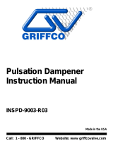
PARTS LIST / SB30X-XXX-X
View for SB30X-XXX-T (PTFE diaphragm) con guration only.
COLOR CODE
Diaphragm
Material Color
Nitrile Black
Santoprene Tan
Santoprene (back-up) Green
PTFE White
Viton Yellow (-)
(-) Dash
26
d
(
Figure 3
4
8
7
Santoprene
PTFE
181
d
29
68
)
131
c
173
1
107
186
10
Apply Lubriplate FML-2 grease
101
19
43
201
70
c
c
173
c
172
103
c
144
2
5
7
6
9
)
14
4
)
d
26
15 27
d
(
196
c
3
Torque Sequence
3
2
7
5
1
8
6
4
11
c
11
c

Page 6 of 8 SB30X-XXX-X (en)
Figure 4
TROUBLE SHOOTING
No dampening e ect or erratic performance.
Check for diaphragm rupture.
Check for blocked or restricted outlet hoses.
Check the air supply. Make certain the air pressure to the shock
blocker is equal to the uid pressure.
Constant air leakage:
- from exhaust port.
Check for damaged (172 and 173) “O” rings.
- from air cap.
Check the tightness of (27) screws.
y
y
y
y
y
Air bubbles in product discharge.
Check connections of the pump’s suction plumbing.
Check tightness of (14) diaphragm screw.
Fluid leakage:
- from exhaust port.
Check for diaphragm rupture.
- from ange.
Check for damaged (11) “O” ring.
Check the tightness of (26) screws.
- from uid cap.
Check air pressure to the valve block (relieve uid pressure).
Check the tightness of (27) screws.
Check for cracks. Discontinue use.
y
y
y
y
y
y
y
y
TYPICAL CROSS SECTION

SB30X-XXX-X (en) Page 7 of 8
DIMENSIONAL DATA
Dimensions shown are for reference only, they are displayed in inches and millimeters (mm).
Figure 5
10-7/8” (276 mm)
20-5/8” (524 mm)
15”
(381 mm)
3/4 - 14 N.P.T. Air inlet
3 - 8 N.P.T.F. - 1 or
Rp 3 (3 - 11 BSP parallel)
15”
(381 mm)

Page 8 of 8 SB30X-XXX-X (en)
PN 97999-867
/