Page is loading ...

INSPECT SHIPMENT:
Inspect contents for possible missing or damaged compo-
nents. See Figure 1. This kit includes:
Qty. 1 (one) - Combination Gas Control
Qty. 1 (one) – Installation Instructions
TOOLS REQUIRED:
3/8” Open-end wrench
7/16” Open-end wrench
3/4” Open-end wrench
Pipe Wrench
Soap and water solution
Pipe Thread Sealant
(Certified for use with Natural and LP Gas/Liquefied Petroleum
Gases)
NOTICE: Compounds used on threaded joints of gas piping
shall be resistant to the action of Liquefied Petroleum Gases.
ADDITIONAL INSTRUCTIONS:
Refer to the Use and Care Manual supplied with the water
heater for complete information on the installation, light-
ing, operation and maintenance of the water heater.
1. TURNING OFF GAS SUPPLY TO THE WATER
HEATER:
Set the thermostat dial to the lowest setting “PILOT
LIGHTING” by rotating the thermostat dial on the water
heater's combination gas control clockwise until it
stops. Rotate the gas control knob on the combination gas
control clockwise to the “PILOT” position and then
slightly depress the gas control knob and rotate it clock-
wise to the “OFF” position.
NOTICE: Knob cannot be turned from “PILOT” position
unless pushed down slightly. Do not use force.
Shut off the gas supply at the main gas supply line to the
water heater. Refer to the lighting instruction label located
above the water heaters combination gas control and the
Use and Care manual supplied with the water heater for
additional information on shutting off the gas supply.
2. DRAINING THE WATER HEATER: Shut off the inlet
water supply to the water heater. Connect one end of a
garden hose to the water heater's drain valve and route the
other hose end to a drain or suitable draining area. Open a
hot water faucet to allow air to flow into the water heater
tank then open the water heater's drain valve. See Figure 2.
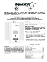
3. DISCONNECTION OF THERMOCOUPLE, PILOT
SUPPLY TUBE, BURNER SUPPLY TUBE AND
PIEZO WIRING FROM THE COMBINATION GAS
CONTROL:
Locate the piezo wiring, slide the protective wire insula-
tor “boot” away from the piezo generator, and then care-
fully pull apart the connection. See Figure 3. Using a 3/8”
open-end wrench, disconnect the thermocouple from the
combination gas control. Using a 7/16” open-end wrench,
disconnect the pilot supply line from the combination gas
control. Using a 3/4” open-end wrench, disconnect the
burner supply tube from the combination gas control. See
Figure 3.
NOTICE: LP Gas Combination Controls use left-handed
threads on the burner supply tube nut.
INSTALLATION INSTRUCTIONS
(FVIR) Atmospheric White-Rodgers Combination Control Replacement Kit
Read these instructions thoroughly and understand all steps and procedures before
proceeding with the installation.
Figure 1
Figure 2
Drain Valve
1
Thermocouple
Burner Supply
Tube
Piezo Ignitor
Wire Boot
Pilot Supply Tube
Figure 3
Piezo Generator
AP14447 (02/08)

4. COMBINATION GAS CONTROL REMOVAL:
With the gas supply shut off, disconnect the main gas supply
piping from the combination gas control. After the water
heater is completely drained, screw a suitable length of ½”
NPT pipe into the gas inlet connection of the combination
gas control. Rotate the control counter clockwise until
removed. Remove the ½” NPT pipe. See Figure 4.
5. NEW COMBINATION GAS CONTROL INSTALLATION:
Ensure the replacement combination gas control is correct for
the gas usage of the water heater. Hand start threading the con-
trol into the water heater. Install the suitable length of ½“ NPT
pipe previously used to the gas inlet of new control. Rotate the
control by turning clockwise until the control is tight and
in the upright position. Remove the ½” NPT pipe.
6. CONNECTION OF THERMOCOUPLE, PILOT SUPPLY
TUBE, BURNER SUPPLY TUBE AND PIEZO WIRING
TO THE COMBINATION GAS CONTROL:
Install the inverted flare end of the burner supply tube into the
combination gas control. Hand thread the hex nut fitting on
the burner supply tube into the control. Ensure that the fitting
is properly aligned with the control, otherwise cross threading
of the connection will occur. Tighten the fitting using a 3/4”
open-end wrench. See Figure 5.
NOTICE: LP Gas Combination Controls use left-handed
threads on the burner supply tube nut.
Install the end of the pilot supply tube into the combination gas
control. Hand thread the hex nut fitting on the pilot supply tube
into the control. Ensure that the fitting is properly aligned with
the control, otherwise cross threading of the connection will
occur. Tighten the fitting using a 7/16” open-end wrench. See
Figure 5.
Install the end of the thermocouple into the combination gas
control. Hand thread the hex nut fitting on the thermocouple
into the combination gas control. Ensure that the fitting is
properly aligned with the control, otherwise cross threading of
the connection will occur. Tighten the fitting with a 3/8” Open
-end wrench. See Figure 5.
Locate the wire coming from the piezo generator and the wire
coming out of the burner access door. Push the wire connec-
tors together and slide the protective wire insulator “boot” over
the connection. See Figure 5.
7. CONNECTION OF THE MAIN GAS SUPPLY TO THE
COMBINATION GAS CONTROL:
Reconnect the main gas supply piping to the combination gas
control. Use pipe thread sealant certified for use with Natural
and LP Gas/Liquefied Petroleum Gases.
NOTICE: Compounds used on threaded joints of gas piping
shall be resistant to the action of Liquefied Petroleum Gases.
8. REFILLING THE WATER HEATER:
Disconnect the garden hose from the water heater’s drain
valve. Close the drain valve and turn on the inlet water
supply to the water heater. Open all hot water faucets to
allow all trapped air to escape. Let the water heater fill until
a steady stream of water is observed coming from all hot
water faucets then close all faucets.
9. TURN ON GAS TO THE WATER HEATER:
Turn on the main gas supply to the water heater. Check for
leaks on the inlet supply piping using a soap and water solu-
tion.
NOTICE: If the soap and water solution bubbles up, there
is a leak and the inlet supply piping must be tightened and
checked again.
10. LIGHTING AND OPERATION INSTRUCTIONS:
Follow the “FOR YOUR SAFETY READ BEFORE
OPERATING” and “LIGHTING INSTRUCTIONS” on the
label above the combination gas control or in the Use and
Care Manual supplied with the water heater:
With the pilot and main burner in operation, use a soap and
water solution to check for gas leaks at the burner supply
and pilot tube connections.
NOTICE: If the soap and water solution bubbles up, there
is a leak and the fittings must be tightened and checked
again.
IMPORTANT: If the leak(s) cannot be eliminated, turn
off the gas supply to the water heater and contact the water
heater manufacturer at 1-800-432-8373.
Figure 4
1/2" NPT Pipe
Gas Inlet
Connection
2
Connections Ends:
Burner Supply Tube
Piezo Ignitor
Wire "Boot"
Figure 5
Pilot Supply Tube
Thermocouple
Thermocouple
Burner Supply
Tube
Pilot Supply Tube
Piezo Generator

11. TEMPERATURE SETTING:
▲DANGER: Hotter water increases the potential for
Hot Water SCALDS.
Turn the temperature dial to the desired setting. A tempera-
ture setting of 120° F (49°C) or less is recommended as a
usable water temperature.
The illustration in Figure 6 details the approximate water
temperature for each mark on the Gas Control Temperature
Dial.
80°F
90°F
100°F
110°F
120°F
130°F
150°F
160°F
Temperatures are approximate
Figure 6
140°F
3
Pilot Supply Tube

/