Page is loading ...

INSPECT SHIPMENT:
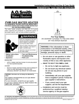
Inspect contents for possible missing or damaged compo-
nents. See Figure 1. This kit includes:
Qty. 1 (one) – Combination Gas Control - See Figure 1.
Qty. 1 (one) – Installation Instructions
Qty. 1 (one) – Label – Lighting Instructions (English)
Qty. 1 (one) – Label – Lighting Instructions (French)
Qty. 1 (one) – Use & Care Manual – USA (English)
Qty. 1 (one) – Use & Care Manual – Canada (English)
Qty. 1 (one) – Use & Care Manual – Canada (French)
TOOLS REQUIRED:
3/8” Open-end wrench
7/16” Open-end wrench
3/4” Open-end wrench
Pipe Wrench
Soap and water solution
1/2” NPT, approximately 8” – 12” pipe length
UL 510 and/or CSA C22.2 No. 197 certified PVC electrical
tape
Pipe Thread Sealant - (Certified for use with Natural and LP
Gas/Liquefied Petroleum Gases)
NOTICE: Compounds used on threaded joints of gas piping
shall be resistant to the action of Liquefied Petroleum Gases.
ADDITIONAL INSTRUCTIONS:
Refer to the Use and Care Manual supplied with the water
heater for complete information on the installation, lighting
instructions, operation and maintenance of the water heater
with the RobertShaw combination gas control.
Refer to the Use and Care Manuals supplied with this kit
for complete information on the installation, operation and
maintenance of the water heater when equipped with the
new replacement White-Rodgers combination gas control.
1. TURNING OFF GAS SUPPLY TO THE WATER
HEATER:
Set the thermostat dial to the lowest setting “VACATION”
by rotating the thermostat dial on the water heater's com-
bination gas control counter clockwise Q until it stops.
Rotate the gas control knob on the combination gas control
clockwise P to the “OFF” position.
Shut off the gas supply at the main gas supply line to the
water heater. Refer to the lighting instruction label located
above the water heaters combination gas control and the
Use and Care manual supplied with the water heater for
additional information on shutting off the gas supply.
2. DRAINING THE WATER HEATER: Shut off the inlet
water supply to the water heater. Connect one end of a
garden hose to the water heater's drain valve and route the
other hose end to a drain or suitable draining area. Open a
hot water faucet to allow air to flow into the water heater
tank then open the water heater's drain valve. See Figure 2.
3. DISCONNECTION OF THERMOCOUPLE, PILOT
SUPPLY TUBE, BURNER SUPPLY TUBE, AND
PIEZO WIRING FROM THE COMBINATION GAS
CONTROL:
Locate the piezo wiring and carefully pull apart the con-
nection from the piezo generator. Using a 3/8” open-end
wrench, disconnect the thermocouple from the water
heater’s combination gas control. Using a 7/16” open-end
wrench, disconnect the pilot supply line from the combina-
tion gas control. Using a 3/4” open-end wrench, discon-
nect the burner supply tube from the combination gas con-
trol. See Figure 2.
NOTICE: LP Gas Combination Controls use left-handed
threads on the burner supply tube nut.
4. ROBERTSHAW COMBINATION GAS CONTROL
REMOVAL: With the gas supply shut off, disconnect the
main gas supply piping from the combination gas control.
After the water heater is completely drained, screw a suit-
able length of ½” NPT pipe into the gas inlet connection
of the combination gas control. Rotate the control counter
clockwise Q until removed. Remove the ½” NPT pipe. See
Figure 3.
5. NEW WHITE- RODGERS COMBINATION GAS
CONTROL INSTALLATION: Ensure the replacement com-
bination gas control is correct for the gas usage of the water
INSTALLATION INSTRUCTIONS
Atmospheric RobertShaw to White-Rodgers Combination Gas Control Replacement Kit
[Flammable Vapor Ignition Resistant (FVIR) Models]
Read these instructions thoroughly to understand all steps and procedures before proceeding with the
installation.
1
AP14620 (08/08)
Figure 1
Combination Gas
Control
Thermocouple
Burner Supply
Tube
Pilot Supply Tube
Figure 2
Drain
Valve
Piezo

heater. Hand start threading the control into the water heater.
Install the suitable length of ½“ NPT pipe previously used
to the gas inlet of new control. Rotate the control by turning
clockwise P until the control is tight and in the upright posi-
tion. Remove the ½” NPT pipe.
6. CONNECTION OF BURNER SUPPLY TUBE,
PILOT SUPPLY TUBE, THERMOCOUPLE, AND
IGNITER WIRE TO THE NEW COMBINATION GAS
CONTROL:
Install the inverted flare end of the burner supply tube into the
combination gas control. Hand thread the hex nut fitting on
the burner supply tube into the control. Ensure that the fitting
is properly aligned with the control, otherwise cross threading
of the connection will occur. Tighten the fitting using a ‘3/4”
open-end wrench. See Figure 4.
NOTICE: LP Gas Combination Controls use left-handed
threads on the burner supply tube nut.
Install the end of the pilot supply tube into the combination
gas control. Hand thread the hex nut fitting on the pilot supply
tube into the control. Ensure that the fitting is properly aligned
with the control, otherwise cross threading of the connection
will occur. Tighten the fitting using a 7/16” open-end wrench.
See Figure 4.
Install the end of the thermocouple into the combination gas
control. Hand thread the hex nut fitting on the thermocouple
into the combination gas control. Ensure that the fitting is
properly aligned with the control, otherwise cross threading of
the connection will occur. Tighten the fitting with a 3/8” Open-
end wrench. See Figure 4.
Locate the wire coming from the piezo generator supplied with
the new replacement combination gas control and connect it to
the igniter wire coming out of the burner access door. Using
UL 510 and/or CSA C22.2 No. 197 certified PVC electri-
cal tape, completely wrap the exposed metal connectors. See
Figure 4.
IMPORTANT: Any exposed portion of the metal connec-
tors may prevent the piezo generator from operating prop-
erly.
7. CONNECTION OF THE MAIN GAS SUPPLY TO THE
COMBINATION GAS CONTROL:
Reconnect the main gas supply piping to the combination gas
control. Use pipe thread sealant certified for use with Natural
and LP Gas/Liquefied Petroleum Gases.
NOTICE: Compounds used on threaded joints of gas piping
shall be resistant to the action of Liquefied Petroleum Gases.
8. REFILLING THE WATER HEATER:
Disconnect the garden hose from the water heater’s drain
valve. Close the drain valve and turn on the inlet water
supply to the water heater. Open all hot water faucets to
allow all trapped air to escape. Let the water heater fill until
a steady stream of water is observed coming from all hot
water faucets then close all faucets.
9. TURN ON GAS TO THE WATER HEATER:
Turn on the main gas supply to the water heater. Check for
leaks on the inlet supply piping using a soap and water solu-
tion.
NOTICE: If the soap and water solution bubbles up, there
is a leak and the inlet supply piping must be tightened and
checked again.
10. LIGHTING INSTRUCTIONS LABEL(s)
REPLACEMENT:
Locate the new Lighting Instructions Label(s) supplied with
the replacement kit and affix the appropriate label(s) over
the Lighting Instructions Label(s) above the combination
gas control on the water heater.
11. USE AND CARE MANUAL REPLACEMENT:
Discard the old Use and Care Manual and place the new Use
and Care Manual(s) supplied adjacent to the water heater.
IMPORTANT: Retain all new instructions and litera-
ture for future use.
12. LIGHTING AND OPERATION INSTRUCTIONS:
Follow the new “FOR YOUR SAFETY READ BEFORE
OPERATING” and “LIGHTING INSTRUCTIONS” on the
replaced label above the combination gas control or in the
new Use and Care Manual supplied with this Combination
Control Replacement Kit. With the pilot and main burner
in operation, use a soap and water solution to check for gas
leaks at the burner supply and pilot tube connections.
NOTICE: If the soap and water solution bubbles up, there
is a leak and the fittings must be tightened and checked
again.
IMPORTANT: If the leak(s) cannot be eliminated, turn
off the gas supply to the water heater and contact the water
heater manufacturer at 1-800-432-8373.
2
C
A
U
T
I
O
N
T
H
E
R
I
S
K
O
F
S
C
A
L
D
I
N
J
U
R
Y
W
A
T
E
R
I
N
C
R
E
A
S
E
S
H
O
T
T
E
R
W A R N I N G
READ ALL INSTRUCTIONS
BEFORE LIGHTING
Figure 3
1/2" NPT Pipe
Gas Inlet
Connection
Figure 4
Piezo Generator w/wire
Adapter Nut
Thermocouple
Connection
Pilot Supply Tube
Connection
Thermocouple
Burner Supply Tube
Pilot Supply Tube
Ignitor Wire

13. TEMPERATURE SETTING:
DANGER: Hotter water increases the potential for
Hot Water SCALDS.
Turn the temperature dial to the desired setting. A tem-
perature setting of 120°F (49°C) or less is recommended as a
usable water temperature.
The illustration in Figure 5 details the approximate water tem-
perature for each mark on the White-Rodgers Combination
Gas Control Temperature Dial.
80°F
(27°C)
90°F
(32°C)
100°F
(38°C)
110°F
(43°C)
120°F
(49°C)
130°F
(54°C)
150°F
(66°C)
160°F
(71°C)
Temperatures are approximate
Figure 5
140°F
(60°C)
3
!

4
This page intentionally left blank.
/