Page is loading ...

Infinity Supported Application
2008–2010 Dodge Viper 4G
AEM Performance Electronics
AEM Performance Electronics, 2205 126th Street Unit A, Hawthorne, CA 90250
Phone: (310) 484-2322 Fax: (310) 484-0152
http://www.aemelectronics.com
Instruction Part Number:
Document Build 1/6/2015
Instruction
Manual
STOP!
THIS PRODUCT HAS LEGAL RESTRICTIONS.
READ THIS BEFORE INSTALLING/USING!
THIS PRODUCT MAY BE USED SOLELY ON VEHICLES USED IN SANCTIONED COMPETITION WHICH MAY NEVER BE USED UPON A
PUBLIC ROAD OR HIGHWAY, UNLESS PERMITTED BY SPECIFIC REGULATORY EXEMPTION. (VISIT THE “EMISSIONS” PAGE AT HTTP://
WWW.SEMASAN.COM/EMISSIONS FOR STATE BY STATE DETAILS.)
IT IS THE RESPONSIBILITY OF THE INSTALLER AND/OR USER OF THIS PRODUCT TO ENSURE THAT IT IS USED IN COMPLIANCE WITH
ALL APPLICABLE LAWS AND REGULATIONS. IF THIS PRODUCT WAS PURCHASED IN ERROR, DO NOT INSTALL AND/OR USE IT. THE
PURCHASER MUST ARRANGE TO RETURN THE PRODUCT FOR A FULL REFUND.
THIS POLICY ONLY APPLIES TO INSTALLERS AND/OR USERS WHO ARE LOCATED IN THE UNITED STATES; HOWEVER CUSTOMERS
WHO RESIDE IN OTHER COUNTRIES SHOULD ACT IN ACCORDANCE WITH THEIR LOCAL LAWS AND REGULATIONS.
WARNING: This installation is not for the tuning novice! Use this system with EXTREME caution! The AEM
Infinity Programmable EMS allows for total flexibility in engine tuning. Misuse or improper tuning of this
product can destroy your engine! If you are not well versed in engine dynamics and the tuning of engine
management systems DO NOT attempt the installation. Refer the installation to an AEM-trained tuning
shop or call 800-423-0046 for technical assistance.
NOTE: All supplied AEM calibrations, Wizards and other tuning information are offered as potential
starting points only. IT IS THE RESPONSIBILITY OF THE ENGINE TUNER TO ULTIMATELY CONFIRM IF THE
CALIBRATION IS SAFE FOR ITS INTENDED USE. AEM holds no responsibility for any engine damage that
results from the misuse or mistuning of this product!

2
© 2015 AEM Performance Electronics
OVERVIEW
The AEM Infinity EMS can be adapted to most fuel injected engines. When possible, AEM will provide
“base cal” sessions and configuration files for supported applications that have been verified by AEM
engineers. These session and configuration files are starting points only and will need to be modified for
your specific application. This manual lists the files available and suggested changes for your engine. It
also includes a pinout with suggestions for adapting the Infinity ECU to your engine harness. It is the
responsibility of the installer to verify this information before starting the engine.
MODELS
Dodge
2008–2010 Viper with 8.4L V10 engine
DOWNLOADABLE FILES
Files can be downloaded from www.aeminfinity.com. An experienced tuner must be available to configure
and manipulate the data before driving can commence. The Quick Start Guide and Full Manual describe
the steps for logging in and registering at www.aeminfinity.com. These documents are available for
download in the Support section of the AEM Electronics website: http://www.aemelectronics.com/
products/support/instructions.
ADAPTER HARNESS OPTIONS
30-3701 Plug & Pin Kit
This kit includes mating connectors and terminals for the Infinity. It also includes a main relay kit which
is necessary for proper power distribution. This kit is best suited for experienced installers who want to
build their own harness.
30-3702 Harness with Flying Leads
This harness includes a fused power distribution center with main relay. Pre-terminated connectors are
available for the internal UEGO sensors and AEMNet. A bag of multi-color flying leads is included to
simplify custom harness builds.
30-3703 Mini Harness with Pins
This harness includes a fused power distribution center with main relay. Pre-terminated connectors are
available for the internal UEGO sensors and AEMNet. 100 pins and 30 sealing plugs are included.
30-3600 02 Sensor Extension Harness
Extension harness to connect AEM UEGO Wideband 02 sensor to 6-pin Deutsch DTM in Infinity Mini
Harnesses (30-3702/3703).
30-3601 IP67 Comms Cable
USB Mini-B comms cable; 39” long with right angled connector and bayonet style lock.
30-3602 IP67 Logging Cable
USB A-to-A extension cable: 39” long with right angled connector and bayonet style lock.
30-2981 ECU Patch/Extension Harness
Extension harness to connect the factory wiring harness to the factory PCB.

Infinity Supported Application
3
© 2015 AEM Performance Electronics
IMPORTANT APPLICATION NOTES
The test vehicle used for development of this app was a 2010 Viper ACR with ACR-X headers and a
deleted A/C system. Due to a lack of the A/C system and its components, operation of this system was
not verified on the Infinity EMS.
The coils used for testing were “stock” two-wire ignition coils (PN 1-05037127AB). For compatibility with
the Infinity EMS the use of an igniter or CDI that accepts a FALLING edge fire signal is necessary. For
vehicle development three AEM 4 Channel Coil Drivers (PN 30-2840) were used.
The 2008–2010 Dodge Viper uses the Push-Button as an input into the Factory ECU to control ground
for the Starter Relay. An external circuit is utilized to control the Push-Button Start to Starter Relay
interaction. A schematic to build this device is provided in this document. Note if this schematic is
followed the Starter Motor will continue to spin while the Push-Button Start is being held. Continued use
of the Starter Motor once engine is no longer within the cranking RPM range may cause damage to the
Starter Motor, and Engine.
The 2008–2010 Dodge Viper uses a 12 Volt pulse-width modulated signal through the Generator Field
Control wire to control the Generator output. An external circuit is required to provide this signal as the
Infinity is not outfitted with hardware to support this function. A schematic to build this device is provided
in this document.
Caution must be used when tuning Drive By Wire (DBW) values for this application. While creating the
Infinity base session, it was observed that aggressive DBW values may cause the throttle plate to wedge
between the throttle body housing when closing resulting in a DBW_Error_Fatal.
The stock CLT, IAT, MAP, Injectors, Oil Temperature, Oil Pressure sensors have been fully
characterized and their calibrations have been inputted into the base session.
The adapter harness used to mate the Infinity EMS to the stock wiring harness was setup to use the
stock main relay that is already on the vehicle. The stock Oil Pressure, Oil Temperature, Coolant
Temperature, Battery Voltage, Speedometer, and RPM gauges are not supported by the Infinity EMS.

4
© 2015 AEM Performance Electronics
PUSH BUTTON START – STARTER RELAY
Use the following schematic to create a Starter Relay circuit. This circuit will need to be wired into the
Infinity adapter harness.

Infinity Supported Application
5
© 2015 AEM Performance Electronics
GENERATOR CONTROL
Use the following schematic to create a Generator control circuit. This circuit will need to be wired into
the Infinity adapter harness.
GETTING STARTED
Refer to the 10-7100 for EMS 30-7100 Infinity Quick Start Guide for additional information on getting
the engine started with the Infinity EMS
Import Base Session
2008–2010 Dodge Viper base session located in C:\Documents\AEM\Infinity Tuner\Sessions\Base
Sessions

6
© 2015 AEM Performance Electronics
IMPORTANT APPLICATION SPECIFIC SETTINGS
Infinity Tuner Wizard Setup
Engine
In the Wizard Engine tab confirm the following settings:
Engine Displacement (L)= 8.40
Number of Cylinders = 10
Engine Cycle Type = 4 Stroke
Ignition Type = Sequential (Coil On Plug)
Firing Order = 1-10-9-4-3-6-5-8-7-2 Viper Odd Fire
Note: Throttle [%] was used for VE Table Load Axis Selection to create base session.
Cam/Crank
In the Wizard Cam/Crank tab confirm the following setting:
Dodge Viper V10 (2008–2010)
Ignition Sync
Add a text grid control to your layout and select the following channels. Make sure their values match
the settings below for initial timing sync.
TrigOffset [degBTDC] = 4.50
CamSyncAdjustment = 100.00
See QuickStart Guide section Setup: Ignition Sync for instructions on timing sync.
Injector Setup
In the Wizard Injector Setup tab confirm the following setting:
Number of Injectors = 10
Idle
In the Wizard Idle tab confirm the following settings:
Idle Stepper Max Steps = 33
Idle Airflow Invert = Unchecked
DBW Tuning
1) Run Drive By Wire Wizard Setup.

Infinity Supported Application
7
© 2015 AEM Performance Electronics
2) Enter in “Upper” values of DBW_Bias [%] 1d Table. Enter values for DBW_FB_Multiplier.
Note: Caution must be taken when tuning Drive By Wire values.
LowSide Assignment – Coolant Fans
In the Wizard LowSide Assignment tab confirm the following settings:
LS2 Setup:
Frequency = 30 Hz
LS2_Duty X-Axis = Engine Speed [RPM]
LS2_Duty Y-Axis = CoolantFan1On
LS8 Setup:
Frequency = 30 Hz
LS8_Duty X-Axis = Engine Speed [RPM]
LS8_Duty Y-Axis = CoolantFan2On
LowSide Assignment – VVC
In the VVC Wizard tab confirm the following settings:
VVC2A Enable = Checked
Cam 0 Sync = 95
Under “VVC2 Options” confirm the following settings:
VVC2 Failsafe Min = -55
VVC2 Failsafe Max = 5
VVC2 Feedback Min = -30
VVC2 Feedback Max = 30
VVC2 Duty Min = 0
VVC2 Duty Max = 90
VVC2 Proportional Gain = 0.950
VVC2 Integral Gain = 2.500
VVC2 Derivative Gain = 0.050
In the Lowside Assignment Tables tab, configure LS5 as shown below:
Frequency = 250 Hz
LS5_Duty X-Axis = Engine Speed [RPM]
LS5_Duty Y-Axis = VVC2A_Duty [%]
Add a 2D table to the Infinity Tuner layout called “LS5_Duty [%] and configure it exactly as shown below.

8
© 2015 AEM Performance Electronics
LowSide Assignment – Generator Control
In the Lowside Assignment Tables tab, confirm the following settings:
Frequency = 125 Hz
LS6_Duty X-Axis = Engine Speed [RPM]
LS6_Duty Y-Axis = Battery [Volts]
LowSide Assignment – Reverse Lock-Out
In the Lowside Assignment Tables tab, confirm the following settings:
Frequency = 30 Hz
LS7_Duty X-Axis = Vehicle Speed [MPH]
LS7_Duty Y-Axis = Engine Speed [RPM]

Infinity Supported Application
9
© 2015 AEM Performance Electronics
Input Function Assignment
In the Input Function Assignment tab, choose Vehicle Speed Input and confirm the following setting:
Vehicle Speed Calibration = 0.44
PINOUTS
Infinity Pinout
Dedicated
Dedicated and not reconfigurable
Assigned
Assigned but reconfigurable
Available
Available for user setup
Not Applicable
Not used in this configuration
Required
Required for proper function
Infinity
Pin
Hardware Reference
08–10 Dodge
Viper Function
08–10
Dodge
Viper Pin
Destination
Hardware Specification
Notes
External Hbridge
Output of
Generator
Control H-Bridge
C3-5
Pin 1 of TLE 5205-2G Hbridge
External Relay
Ignition Switch
Output (Start)
C3-36
Pin 1 of V23374-A1601-X008 Relay
External Relay
Starter Relay
Control
C4-5
Pin 2 of V23374-A1601-X008 Relay
C1-1
LowsideSwitch_4
A/C Relay
Control
Lowside switch, 4A max,
NO internal flyback diode.
See "LowSide Assignment Tables" for
output assignment.
C1-2
LowsideSwitch_5
LS5
C3-12
Lowside switch, 4A max
with internal flyback diode.
Inductive load should NOT
have full time power.
See Setup Wizard Page "LowSide
Assignment Tables" for output
assignment and 2D table "LS5_Duty
[%]" for activation.
C1-3
LowsideSwitch_6
LS6
Gen Hbridge
control (Pin 5
of TLE 5205-
2G Hbridge)
Lowside switch, 4A max
with internal flyback diode.
Inductive load should NOT
have full time power.
See Setup Wizard Page "LowSide
Assignment Tables" for output
assignment and 2D table "LS6_Duty
[%]" for activation.
C1-4
UEGO 1 Heat
UEGO 1 Heat
Bosch UEGO controller
Lowside switch for UEGO heater
control. Connect to pin 4 of Bosch
UEGO sensor. NOTE that pin 3 of the
Sensor is heater (+) and must be power
by a fused/switched 12V supply.
C1-5
UEGO 1 IA
UEGO 1 IA
Trim Current signal. Connect to pin 2 of
Bosch UEGO sensor.

10
© 2015 AEM Performance Electronics
Infinity
Pin
Hardware Reference
08–10 Dodge
Viper Function
08–10
Dodge
Viper Pin
Destination
Hardware Specification
Notes
C1-6
UEGO 1 IP
UEGO 1 IP
Pumping Current signal. Connect to pin
6 of Bosch UEGO sensor.
C1-7
UEGO 1 UN
UEGO 1 UN
Nernst Voltage signal. Connect to pin 1
of Bosch UEGO sensor.
C1-8
UEGO 1 VM
UEGO 1 VM
Virtual Ground signal. Connect to pin 5
of Bosch UEGO sensor.
C1-9
Flash_Enable
Flash Enable
10K pulldown
Not usually needed for automatic
firmware updates through Infinity
Tuner. If connection errors occur during
update, connect 12 volts to this pin
before proceeding with upgrade.
Disconnect the 12 volts signal after the
update.
C1-10
+12V_R8C_CPU
Battery Perm
Power
C3-21
Dedicated power
management CPU
Full time battery power. MUST be
powered before the ignition switch input
is triggered. (See C1-65.)
C1-11
Coil 4
Coil 4
C2-9
25 mA max source current
0–5V Falling edge fire. DO NOT
connect directly to coil primary. Must
use an ignitor OR CDI that accepts a
FALLING edge fire signal.
C1-12
Coil 3
Coil 3
C1-8
25 mA max source current
0–5V Falling edge fire. DO NOT
connect directly to coil primary. Must
use an ignitor OR CDI that accepts a
FALLING edge fire signal.
C1-13
Coil 2
Coil 2
C2-10
25 mA max source current
0–5V Falling edge fire. DO NOT
connect directly to coil primary. Must
use an ignitor OR CDI that accepts a
FALLING edge fire signal.
C1-14
Coil 1
Coil 1
C2-1
25 mA max source current
0–5V Falling edge fire. DO NOT
connect directly to coil primary. Must
use an ignitor OR CDI that accepts a
FALLING edge fire signal.
C1-15
Coil 6
Coil 6
C2-7
25 mA max source current
0–5V Falling edge fire. DO NOT
connect directly to coil primary. Must
use an ignitor OR CDI that accepts a
FALLING edge fire signal.
C1-16
Coil 5
Coil 5
C1-3
25 mA max source current
0–5V Falling edge fire. DO NOT
connect directly to coil primary. Must
use an ignitor OR CDI that accepts a
FALLING edge fire signal.
C1-17
LowsideSwitch_2
RAD Fan Low
Relay Control
C4-2
Lowside switch, 4A max,
NO internal flyback diode.
See "LowSide Assignment Tables" for
output assignment.

Infinity Supported Application
11
© 2015 AEM Performance Electronics
Infinity
Pin
Hardware Reference
08–10 Dodge
Viper Function
08–10
Dodge
Viper Pin
Destination
Hardware Specification
Notes
C1-18
LowsideSwitch_3
MIL Output
Lowside switch, 4A max
with internal flyback diode.
Inductive load should NOT
have full time power.
See Wizard page "LowSide Assignment
Tables" for output assignment.
MIL Activates when any of the
following flags are true: ErrorAirTemp,
ErrorBaro, ErrorCoolantTemp,
ErrorEBP, ErrorFuelPressure,
UEGO_0_Diag_error,
UEGO_1_Diag_error, ErrorMAFAnalog,
ErrorMAFDigital, ErrorMAP,
ErrorOilPressure, ErrorThrottle.
C1-19
AGND_1
Sensor Ground
C1-17 / C1-
23
Dedicated analog ground
Analog 0–5V sensor ground
C1-20
AGND_1
Sensor Ground
C1-18
Dedicated analog ground
Analog 0–5V sensor ground
C1-21
Crankshaft Position
Sensor Hall
Crankshaft
Position Sensor
Hall
C1-25
10K pullup to 12V. Will work
with ground or floating
switches.
See Setup Wizard page Cam/Crank for
options.
C1-22
Camshaft Position
Sensor 1 Hall
Camshaft
Position Sensor
1 Hall
C1-22
10K pullup to 12V. Will work
with ground or floating
switches.
See Setup Wizard page Cam/Crank for
options.
C1-23
Digital_In_2
Camshaft
Position Sensor
2 Hall
10K pullup to 12V. Will work
with ground or floating
switches.
See Setup Wizard page Cam/Crank for
options.
C1-24
Digital_In_3
Turbo Speed Hz
10K pullup to 12V. Will work
with ground or floating
switches.
See Setup Wizard page Input Function
Assignment for calibration constant.
TurboSpeed [RPM] = Turbo [Hz] * Turbo
Speed Calibration.
C1-25
Digital_In_4
Vehicle Speed
Sensor
C4-29
10K pullup to 12V. Will work
with ground or floating
switches.
See Setup Wizard page Input Function
Assignment for calibration constant.
C1-26
Digital_In_5
Flex Fuel
10K pullup to 12V. Will work
with ground or floating
switches.
See channel FlexDigitalIn [Hz] for raw
frequency input data.
C1-27
Knock Sensor 1
Knock Sensor 1
C3-34
Dedicated knock signal
processor
See Setup Wizard page Knock Setup
for options.
C1-28
Knock Sensor 2
Knock Sensor 2
C3-26
Dedicated knock signal
processor
See Setup Wizard page Knock Setup
for options.
C1-29
+12V_Relay_Control
+12V Relay
Control
C3-19 / C2-
17
0.7A max ground sink for
external relay control
Will activate at key on and at key off
according to the configuration settings.
C1-30
Power Ground
Ground
C3-27
Power Ground
Connect directly to battery ground.
C1-31
CANL_Aout
AEMNet CANL
Dedicated High Speed CAN
Transceiver
Recommend twisted pair (one twist per
2") with terminating resistor. Contact
AEM for additional information.

12
© 2015 AEM Performance Electronics
Infinity
Pin
Hardware Reference
08–10 Dodge
Viper Function
08–10
Dodge
Viper Pin
Destination
Hardware Specification
Notes
C1-32
CANH_Aout
AEMNet CANH
Dedicated High Speed CAN
Transceiver
Recommend twisted pair (one twist per
2") with terminating resistor. Contact
AEM for additional information.
C1-33
LowsideSwitch_1
Boost Control
Lowside switch, 4A max
with internal flyback diode.
Inductive load should NOT
have full time power.
See Setup Wizard page Boost Control
for options. Monitor BoostControl [%]
channel for output state.
C1-34
Lowside Fuel Pump
drive
Fuel Pump
C4-4
Lowside switch, 4A max,
NO internal flyback diode.
Switched ground. Will prime for 2
seconds at key on and activate if RPM
> 0.
C1-35
Analog_In_7
Throttle Position
Sensor
C2-23
12 bit A/D, 100K pullup to
5V
0–5V analog signal. Use +5V Out pins
as power supply and Sensor Ground
pins as the low reference. Do not
connect signals referenced to +12V as
this can permanently damage the ECU.
See the Setup Wizard Set Throttle
Range page for automatic min/max
calibration. Monitor the Throttle [%]
channel. Also DB1_TPSA [%] for DBW
applications.
C1-36
Analog_In_8
MAP Sensor
C1-33
12 bit A/D, 100K pullup to
5V
0–5V analog signal. Use +5V Out pins
as power supply and Sensor Ground
pins as the low reference. Do not
connect signals referenced to +12V as
this can permanently damage the ECU.
See the Setup Wizard Set Manifold
Pressure page for setup and
calibration. Monitor the MAP [kPa]
channel.
C1-37
Analog_In_9
Fuel Pressure
12 bit A/D, 100K pullup to
5V
0–5V analog signal. Use +5V Out pins
as power supply and Sensor Ground
pins as the low reference. Do not
connect signals referenced to +12V as
this can permanently damage the ECU.
See the Setup Wizard Fuel Pressure
page for setup and calibration. Monitor
the FuelPressure [psig] channel.
C1-38
Analog_In_10
Baro Sensor
12 bit A/D, 100K pullup to
5V
0–5V analog signal. Use +5V Out pins
as power supply and Sensor Ground
pins as the low reference. Do not
connect signals referenced to +12V as
this can permanently damage the ECU.
See the Setup Wizard Barometric
Pressure page for setup and
calibration. Monitor the BaroPress [kPa]
channel.
C1-39
Analog_In_11
Shift Switch
Input
12 bit A/D, 100K pullup to
5V
0–5V analog signal. Use +5V Out pins
as power supply and Sensor Ground
pins as the low reference. Do not
connect signals referenced to +12V as
this can permanently damage the
ECU.
See the 1D lookup table 'ShiftSwitch'
for setup. Also assignable to multiple
functions. See Setup Wizard for
details.

Infinity Supported Application
13
© 2015 AEM Performance Electronics
Infinity
Pin
Hardware Reference
08–10 Dodge
Viper Function
08–10
Dodge
Viper Pin
Destination
Hardware Specification
Notes
C1-40
Analog_In_12
Mode Switch
12 bit A/D, 100K pullup to
5V
0–5V analog signal. Use +5V Out pins
as power supply and Sensor Ground
pins as the low reference. Do not
connect signals referenced to +12V as
this can permanently damage the
ECU.
See the 1D lookup table 'ModeSwitch'
for input state.
A multi-position rotary switch such as
AEM P/N 30-2056 is recommended.
Also assignable to multiple functions.
See Setup Wizard for details.
C1-41
+5V_Out_1
+5V Out
C1-27 / +5V
of TLE 5205-
2G Hbridge
Regulated, fused +5V
supply for sensor power
Analog sensor power
C1-42
+5V_Out_1
+5V Out
C2-29
Regulated, fused +5V
supply for sensor power
Analog sensor power
C1-43
HighsideSwitch_1
HS1 (switched
12V)
0.7A max, High Side Solid
State Relay
See Setup Wizard page 'HighSide
Assigment Tables' for configuration
options. See 2D lookup table
'HS1_Table' for activation settings.
C1-44
HighsideSwitch_0
VTEC
0.7A max, High Side Solid
State Relay
See Setup Wizard page 'HighSide
Assigment Tables' for configuration
options.
See 2D lookup table 'HS0_Table' for
activation settings.
See Setup Wizard page 'VTEC' for
default activation criteria.
C1-45
Crankshaft Position
Sensor VR+
Crankshaft
Position Sensor
VR+
Differential Variable
Reluctance Zero Cross
Detection
See Setup Wizard page Cam/Crank for
options.
C1-46
Crankshaft Position
Sensor VR-
Crankshaft
Position Sensor
VR-
See Setup Wizard page Cam/Crank for
options.
C1-47
Camshaft Position
Sensor 1 VR-
Camshaft
Position Sensor
1 VR-
Differential Variable
Reluctance Zero Cross
Detection
See Setup Wizard page Cam/Crank for
options.
C1-48
Camshaft Position
Sensor 1 VR+
Camshaft
Position Sensor
1 VR+
See Setup Wizard page Cam/Crank for
options.
C1-49
VR+_In_2
Non Driven Left
Wheel Speed
Sensor +
Differential Variable
Reluctance Zero Cross
Detection
See Non Driven Wheel Speed
Calibration in the Setup Wizard Input
Function Assignment page.
C1-50
VR-_In_2
Non Driven Left
Wheel Speed
Sensor -
C1-51
VR-_In_3
Driven Left
Wheel Speed
Sensor -
Differential Variable
Reluctance Zero Cross
Detection
See Driven Wheel Speed Calibration in
the Setup Wizard Input Function
Assignment page.

14
© 2015 AEM Performance Electronics
Infinity
Pin
Hardware Reference
08–10 Dodge
Viper Function
08–10
Dodge
Viper Pin
Destination
Hardware Specification
Notes
C1-52
VR+_In_3
Driven Left
Wheel Speed
Sensor +
C1-53
DBW1 Motor -
DBW Motor
Control Close
C2-16
5.0A max Throttle Control
Hbridge Drive
+12V to close
C1-54
DBW1 Motor +
DBW Motor
Control Open
C2-6
5.0A max Throttle Control
Hbridge Drive
+12V to open
C1-55
Power Ground
Ground
C3-29
Power Ground
Connect directly to battery ground.
C1-56
Injector 6
Injector 6
C2-4
Saturated or peak and hold,
3A max continuous
Injector 6
C1-57
Injector 5
Injector 5
C1-6
Saturated or peak and hold,
3A max continuous
Injector 5
C1-58
Injector 4
Injector 4
C2-14
Saturated or peak and hold,
3A max continuous
Injector 4
C1-59
Injector 3
Injector 3
C1-7
Saturated or peak and hold,
3A max continuous
Injector 3
C1-60
Power Ground
Ground
C3-30 / Pins
4, 3, and
Capacitor of
TLE 5205-2G
Hbridge
Power Ground
Connect directly to battery ground.
C1-61
+12V
+12V In
C3-11 / C3-
20 / Pin 6 of
TLE 5205-2G
Hbridge
12 volt power from relay
12 volt power from relay. Relay must
be controlled by +12V Relay Control
signal, pin C1-29 above.
C1-62
Injector 2
Injector 2
C2-5
Saturated or peak and hold,
3A max continuous
Injector 2
C1-63
Injector 1
Injector 1
C2-11
Saturated or peak and hold,
3A max continuous
Injector 1
C1-64
+12V
+12V In
12 volt power from relay
12 volt power from relay. Relay must
be controlled by +12V Relay Control
signal pin C1-29 above.
C1-65
+12V_SW
Ignition Switch
C1-12
10K pulldown
Full time battery power must be
available at C1-10 before this input is
triggered.
C1-66
Analog_In_Temp_1
Coolant Temp
Sensor
C3-24
12 bit A/D, 2.49K pullup to
5V
See "Coolant Temperature" Setup
Wizard for selection.
C1-67
Analog_In_Temp_2
Intake Air
Temperature
C3-1
12 bit A/D, 2.49K pullup to
5V
See "Air Temperature" Setup Wizard for
selection.

Infinity Supported Application
15
© 2015 AEM Performance Electronics
Infinity
Pin
Hardware Reference
08–10 Dodge
Viper Function
08–10
Dodge
Viper Pin
Destination
Hardware Specification
Notes
C1-68
Harness_Analog_In_Te
mp_3
Oil Temperature
Sensor
C3-33
12 bit A/D, 2.49K pullup to
5V
See 1D table OilTempCal table for
calibration data and OilTemp [C] for
channel data.
C1-69
Stepper_2A
Stepper 2A
Automotive, Programmable
Stepper Driver, up to 28V
and ±1.4A
Be sure that each internal coil of the
stepper motor is properly paired with
the 1A/1B and 2A/2B ECU outputs.
Supports Bi-Polar stepper motors only.
C1-70
Stepper_1A
Stepper 1A
Automotive, Programmable
Stepper Driver, up to 28V
and ±1.4A
Be sure that each internal coil of the
stepper motor is properly paired with
the 1A/1B and 2A/2B ECU outputs.
Supports Bi-Polar stepper motors only.
C1-71
Stepper_2B
Stepper 2B
Automotive, Programmable
Stepper Driver, up to 28V
and ±1.4A
Be sure that each internal coil of the
stepper motor is properly paired with
the 1A/1B and 2A/2B ECU outputs.
Supports Bi-Polar stepper motors only.
C1-72
Stepper_1B
Stepper 1B
Automotive, Programmable
Stepper Driver, up to 28V
and ±1.4A
Be sure that each internal coil of the
stepper motor is properly paired with
the 1A/1B and 2A/2B ECU outputs.
Supports Bi-Polar stepper motors only.
C1-73
Power Ground
Ground
Power Ground
Connect directly to battery ground.
C2-1
DBW2 Motor +
DBW Motor
Control Open
C2-8
5.0A max Throttle Control
Hbridge Drive
+12V to open
C2-2
DBW2 Motor -
DBW Motor
Control Close
C2-18
5.0A max Throttle Control
Hbridge Drive
+12V to close
C2-3
Power Ground
Ground
C3-31
Power Ground
Connect directly to battery ground.
C2-4
Injector 7
Injector 7
C1-5
Saturated or peak and hold,
3A max continuous
Injector 7
C2-5
Injector 8
Injector 8
C2-13
Saturated or peak and hold,
3A max continuous
Injector 8
C2-6
Injector 9
Injector 9
C1-4
Saturated or peak and hold,
3A max continuous
Injector 9
C2-7
Injector 10
Injector 10
C2-12
Saturated or peak and hold,
3A max continuous
Injector 10
C2-8
Power Ground
Ground
Pin 2 & 3 of
V23374-
A1601-X008
Relay
Power Ground
Connect directly to battery ground.
C2-9
+12V
+12V In
C2-19 / C2-
38
12 volt power from relay
12 volt power from relay. Relay must
be controlled by +12V Relay Control
signal, pin C1-29 above.

16
© 2015 AEM Performance Electronics
Infinity
Pin
Hardware Reference
08–10 Dodge
Viper Function
08–10
Dodge
Viper Pin
Destination
Hardware Specification
Notes
C2-10
Injector 11
Injector 11
Saturated or peak and hold,
3A max continuous
Not used
C2-11
Injector 12
Injector 12
Saturated or peak and hold,
3A max continuous
Not used
C2-12
Analog_In_17
A/C Analog
Request
12 bit A/D, 100K pullup to
5V
0–5V analog signal. Use +5V Out pins
as power supply and Sensor Ground
pins as the low reference. Do not
connect signals referenced to +12V as
this can permanently damage the ECU.
See Setup Wizard Input Functions page
for input selection. See AC_Request_In
1-axis table for activation logic.
C2-13
Analog_In_18
DBW_APP1 [%]
C2-21
12 bit A/D, 100K pullup to
5V
0–5V analog signal. Use +5V Out pins
as power supply and Sensor Ground
pins as the low reference. Do not
connect signals referenced to +12V as
this can permanently damage the ECU.
C2-14
Analog_In_19
DBW_APP2 [%]
C1-32
12 bit A/D, 100K pullup to
5V
0–5V analog signal. Use +5V Out pins
as power supply and Sensor Ground
pins as the low reference. Do not
connect signals referenced to +12V as
this can permanently damage the ECU.
C2-15
Analog_In_Temp_4
Charge Out
Temperature
12 bit A/D, 2.49K pullup to
5V
See ChargeOutTemp [C] table for
calibration data and ChargeOutTemp
[C] for channel data.
C2-16
Analog_In_Temp_5
Airbox Temp /
Intake Air
Temperature
C1-16
12 bit A/D, 2.49K pullup to
5V
See AirboxTemp [C] table for
calibration data and AirboxTemp [C] for
channel data.
C2-17
Analog_In_Temp_6
Fuel
Temperature
12 bit A/D, 2.49K pullup to
5V
See FuelTemp [C] table for calibration
data and FuelTemp [C] for channel
data.
C2-18
Analog_In_13
Oil Pressure
C3-23
12 bit A/D, 100K pullup to
5V
0–5V analog signal. Use +5V Out pins
as power supply and Sensor Ground
pins as the low reference. Do not
connect signals referenced to +12V as
this can permanently damage the ECU.
See Setup Wizard Oil Pressure page for
setup options. See OilPressure [psig]
for channel data.
C2-19
Analog_In_14
Traction Control
Mode /
Sensitivity
12 bit A/D, 100K pullup to
5V
0–5V analog signal. Use +5V Out pins
as power supply and Sensor Ground
pins as the low reference. Do not
connect signals referenced to +12V as
this can permanently damage the ECU.
See the TC_SlipTrgtTrim [MPH] 1-axis
table. A multi-position rotary switch
such as AEM P/N 30-2056 is
recommended.

Infinity Supported Application
17
© 2015 AEM Performance Electronics
Infinity
Pin
Hardware Reference
08–10 Dodge
Viper Function
08–10
Dodge
Viper Pin
Destination
Hardware Specification
Notes
C2-20
Analog_In_15
Exhaust Back
Pressure
12 bit A/D, 100K pullup to
5V
0–5V analog signal. Use +5V Out pins
as power supply and Sensor Ground
pins as the low reference. Do not
connect signals referenced to +12V as
this can permanently damage the ECU.
See Setup Wizard Exhaust Pressure
page for setup options. See EBPress
[kPa] for channel data.
C2-21
Analog_In_16
DBW1_TPSB
[%]
C2-33
12 bit A/D, 100K pullup to
5V
0–5V analog signal. Use +5V Out pins
as power supply and Sensor Ground
pins as the low reference. Do not
connect signals referenced to +12V as
this can permanently damage the ECU.
C2-22
+5V_Out_2
+5V Out
Regulated, fused +5V
supply for sensor power
Analog sensor power
C2-23
+5V_Out_2
+5V Out
Regulated, fused +5V
supply for sensor power
Analog sensor power
C2-24
+5V_Out_2
+5V Out
Regulated, fused +5V
supply for sensor power
Analog sensor power
C2-25
VR+_In_5
Driven Right
Wheel Speed
Sensor +
Differential Variable
Reluctance Zero Cross
Detection
See Driven Wheel Speed Calibration in
the Setup Wizard Input Function
Assignment page.
C2-26
VR-_In_5
Driven Right
Wheel Speed
Sensor -
C2-27
VR-_In_4
Non Driven
Right Wheel
Speed Sensor -
Differential Variable
Reluctance Zero Cross
Detection
See Non Driven Wheel Speed
Calibration in the Setup Wizard Input
Function Assignment page.
C2-28
V R+_In_4
Non Driven
Right Wheel
Speed Sensor +
C2-29
LowsideSwitch_9
Tachometer
Lowside switch, 4A max
with internal flyback diode,
2.2K 12V pullup. Inductive
load should NOT have full
time power.
See Setup Wizard page Tacho for
configuration options.
C2-30
AGND_2
Sensor Ground
C2-15 / C2-
30 / C2-34
Dedicated analog ground
Analog 0–5V sensor ground
C2-31
AGND_2
Sensor Ground
C2-20
Dedicated analog ground
Analog 0–5V sensor ground
C2-32
AGND_2
Sensor Ground
C3-35 / C3-
25 / C3-3
Dedicated analog ground
Analog 0–5V sensor ground

18
© 2015 AEM Performance Electronics
Infinity
Pin
Hardware Reference
08–10 Dodge
Viper Function
08–10
Dodge
Viper Pin
Destination
Hardware Specification
Notes
C2-33
Analog_In_20
Spare Analog
Input
12 bit A/D, 100K pullup to
5V
0–5V analog signal. Use +5V Out pins
as power supply and Sensor Ground
pins as the low reference. Do not
connect signals referenced to +12V as
this can permanently damage the
ECU.
C2-34
Analog_In_21
3 Step Enable
Switch / TPS2A
C2-24
12 bit A/D, 100K pullup to
5V
0–5V analog signal. Use +5V Out pins
as power supply and Sensor Ground
pins as the low reference. Do not
connect signals referenced to +12V as
this can permanently damage the ECU.
See 3StepSwitch 1-axis table for setup.
C2-35
Analog_In_22
USB Logging
Activate
12 bit A/D, 100K pullup to
5V
0–5V analog signal. Use +5V Out pins
as power supply and Sensor Ground
pins as the low reference. Do not
connect signals referenced to +12V as
this can permanently damage the ECU.
See USBLoggingRequestIn channel for
input state. See Setup Wizard page
USB Logging for configuration options.
C2-36
Analog_In_23
Charge Out
Pressure /
TPS2B
C2-22
12 bit A/D, 100K pullup to
5V
0–5V analog signal. Use +5V Out pins
as power supply and Sensor Ground
pins as the low reference. Do not
connect signals referenced to +12V as
this can permanently damage the ECU.
See ChargeOutPress [kPa] channel for
input state. See Setup Wizard page
Charge Out Pressure for calibration
options.
C2-37
Digital_In_6
Spare Digital
Input
No pullup. Will work with
TTL signals.
Input can be assigned to different pins.
See Setup Wizard page Input Function
Assignments for input mapping options.
C2-38
Digital_In_7
Clutch Switch /
Brake Switch
C4-34
No pullup. Will work with
TTL signals.
See ClutchSwitch 1-axis table for setup
options. Input can be assigned to
different pins. See Setup Wizard page
Input Function Assignments for input
mapping options.
C2-39
Power Ground
Ground
C2-27
Power Ground
Connect directly to battery ground.
C2-40
Power Ground
Ground
C2-28
Power Ground
Connect directly to battery ground.
C2-41
CanH_Bout
CANH
Dedicated High Speed CAN
Transceiver
Not used
C2-42
CanL_Bout
CANL
Dedicated High Speed CAN
Transceiver
Not used

Infinity Supported Application
19
© 2015 AEM Performance Electronics
Infinity
Pin
Hardware Reference
08–10 Dodge
Viper Function
08–10
Dodge
Viper Pin
Destination
Hardware Specification
Notes
C2-43
LowsideSwitch_8
RAD Fan Relay
/ Control Engine
Protect Out
C4-3
Lowside switch, 4A max
with internal flyback diode.
Inductive load should NOT
have full time power.
See Spare GPO1 Basic Setup section
of User GPIOs and PWM Setup Wizard
page LowSide Assignment Tables for
additional options.
Activates if any of the following flags
are true: OilPressProtectOut,
LeanProtectOut, CoolantProtect.
Output can be assigned to other
functions. See Setup Wizard page
LowSide Assignment Tables for
additional options.
C2-44
LowsideSwitch_7
Reverse Lock-
Out Control
C4-1
Lowside switch, 4A max
with internal flyback diode.
Inductive load should NOT
have full time power.
See Spare GPO1 Basic Setup section
of User GPIOs and PWM Setup Wizard
page LowSide Assignment Tables for
additional options.
C2-45
UEGO 2 VM
UEGO 2 VM
Bosch UEGO Controller
Virtual Ground signal. Connect to pin 5
of Bosch UEGO sensor.
C2-46
UEGO 2 UN
UEGO 2 UN
Nernst Voltage signal. Connect to pin 1
of Bosch UEGO sensor.
C2-47
UEGO 2 IP
UEGO 2 IP
Pumping Current signal. Connect to pin
6 of Bosch UEGO sensor.
C2-48
UEGO 2 IA
UEGO 2 IA
Trim Current signal. Connect to pin 2 of
Bosch UEGO sensor.
C2-49
UEGO 2 HEAT
UEGO 2 HEAT
Lowside switch for UEGO heater
control. Connect to pin 4 of Bosch
UEGO sensor. NOTE that pin 3 of the
Sensor is heater (+) and must be power
by a fused/switched 12V supply.
C2-50
+12V_R8C_CPU
Battery Perm
Power
Dedicated power
management CPU
Optional full time battery power. MUST
be powered before the ignition switch
input is triggered. (See C1-65.)
C2-51
Coil 7
Coil 7
C1-2
25 mA max source current
0–5V Falling edge fire. DO NOT
connect directly to coil primary. Must
use an ignitor OR CDI that accepts a
FALLING edge fire signal.
C2-52
Coil 8
Coil 8
C2-3
25 mA max source current
0–5V Falling edge fire. DO NOT
connect directly to coil primary. Must
use an ignitor OR CDI that accepts a
FALLING edge fire signal.
C2-53
Coil 9
Coil 9
C1-1
25 mA max source current
0–5V Falling edge fire. DO NOT
connect directly to coil primary. Must
use an ignitor OR CDI that accepts a
FALLING edge fire signal.
C2-54
Coil 10
Coil 10
C2-2
25 mA max source current
0–5V Falling edge fire. DO NOT
connect directly to coil primary. Must
use an ignitor OR CDI that accepts a
FALLING edge fire signal.

20
© 2015 AEM Performance Electronics
Infinity
Pin
Hardware Reference
08–10 Dodge
Viper Function
08–10
Dodge
Viper Pin
Destination
Hardware Specification
Notes
C2-55
HighsideSwitch_2
Fuel Pump
Multi-function pin depending
on hardware configuration
+12V High Side Drive. Will prime for 2
seconds at key on and activate if RPM
> 0.
C2-56
Not used
Not used
Not used
Not used
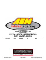
Dodge Pin Numbering
2008–2010 Dodge Viper Harness Connnectors Viewed from Terminal Side
Infinity Pin Numbering
AEM Infinity Connectors Viewed from Wire Side
/