Page is loading ...

Storage Infrastructure and Solutions Engineering
Dell Product Group
October 2012
Sizing and Best Practices for Deploying
VMware View 5.1 on VMware vSphere 5.0 U1
with Dell EqualLogic Storage
A Dell EqualLogic Best Practices Technical White Paper
This document has been archived and will no longer be maintained or updated. For more
information go to the Storage Solutions Technical Documents page on Dell TechCenter
or contact support.

BP1033 Deploying VMware View 5.1 on VMware vSphere 5.0 U1 with Dell EqualLogic Storage
2
© 2012 Dell Inc. All rights reserved. Reproduction of this material in any manner whatsoever without the express
written permission of Dell Inc. is strictly forbidden. For more information, contact Dell.
Dell, the Dell logo, and the Dell badge, PowerConnect™, EqualLogic™, PowerEdge™ and PowerVault™ are
trademarks of Dell Inc. Broadcom® and NetXtreme® are registered trademarks of Broadcom Corporation. Intel® is a
registered trademark of Intel Corporation in the U.S. and other countries. VMware®, Virtual SMP®, vMotion®,
vCenter®, and vSphere® are registered trademarks or trademarks of VMWare, Inc. in the United States or other
countries. Microsoft®, Windows®, Windows Server®, Internet Explorer®, SQL Server, and Active Directory® are either
trademarks or registered trademarks of Microsoft Corporation in the United States and/or other countries

BP1033 Deploying VMware View 5.1 on VMware vSphere 5.0 U1 with Dell EqualLogic Storage
3
Table of contents
Acknowledgements .......................................................................................................................................................................... 6
Feedback ............................................................................................................................................................................................ 6
Executive summary .......................................................................................................................................................................... 7
Audience ............................................................................................................................................................................................. 8
1 Introduction ............................................................................................................................................................................ 9
2 Desktop Virtualization with VMware View ....................................................................................................................... 10
2.1 VMware View components .............................................................................................................................................. 10
2.2 Virtual desktops .................................................................................................................................................................. 10
2.3 VMware View desktop pools ............................................................................................................................................ 10
2.4 Using linked clones ............................................................................................................................................................. 11
2.5 VMware View Storage Accelerator ................................................................................................................................... 11
3 Infrastructure and test configuration................................................................................................................................ 13
3.1 Component design ............................................................................................................................................................ 13
3.2 iSCSI SAN configuration .................................................................................................................................................... 14
3.3 EqualLogic storage array configuration ......................................................................................................................... 15
3.4 ESXi host network configuration ..................................................................................................................................... 16
3.5 VMware View configuration ............................................................................................................................................. 16
3.6 VMware View Pool configuration .................................................................................................................................... 16
3.7 Windows 7 VM configuration ........................................................................................................................................... 17
4 View test methodology ....................................................................................................................................................... 18
4.1 Test objectives .................................................................................................................................................................... 18
4.2 Test approach ..................................................................................................................................................................... 18
4.3 Test tools ............................................................................................................................................................................. 18
4.3.1 Load generation ............................................................................................................................................................ 18
4.3.2 Monitoring tools ........................................................................................................................................................... 19
4.4 Test criteria .......................................................................................................................................................................... 19
4.4.1 Storage capacity and I/O latency .............................................................................................................................. 19
4.4.2 System utilization at the hypervisor .......................................................................................................................... 19
4.4.3 Virtual desktop user experience ................................................................................................................................. 19
4.5 Test setup............................................................................................................................................................................. 20
5 Test results and analysis ...................................................................................................................................................... 22
5.1 Test scenarios ..................................................................................................................................................................... 22

BP1033 Deploying VMware View 5.1 on VMware vSphere 5.0 U1 with Dell EqualLogic Storage
4
5.2 View Storage Accelerator/CBRC benefits ...................................................................................................................... 22
5.3 Boot storm I/O .................................................................................................................................................................... 24
5.4 Task worker – Login storm and steady state I/O ......................................................................................................... 28
5.4.1 Login storm I/O ............................................................................................................................................................. 28
5.4.2 Steady state I/O ............................................................................................................................................................. 30
5.4.3 Server host performance ............................................................................................................................................. 31
5.4.4 User experience monitoring ....................................................................................................................................... 33
5.5 Results summary ................................................................................................................................................................ 34
6 Sizing guidelines for EqualLogic SANs ............................................................................................................................. 35
6.1 Capacity sizing considerations ........................................................................................................................................ 35
6.1.1 VMware View Accelerator sizing ................................................................................................................................ 36
6.1.2 Base image datastore ................................................................................................................................................... 36
6.1.3 Replica datastore .......................................................................................................................................................... 36
6.1.4 Linked clone datastores ............................................................................................................................................... 36
6.2 Performance sizing considerations ................................................................................................................................. 37
6.2.1 Boot storm sizing considerations .............................................................................................................................. 37
6.2.2 Login storm and steady state sizing considerations .............................................................................................. 38
7 Best Practices ........................................................................................................................................................................ 39
7.1 Application layer ................................................................................................................................................................. 39
7.1.1 Implement roaming profiles and folder redirection ............................................................................................... 39
7.1.2 Boot and login storm considerations ....................................................................................................................... 39
7.1.3 Windows 7 master image for desktop VMs .............................................................................................................. 39
7.1.4 SSL certificate requirements ....................................................................................................................................... 39
7.1.5 VMware View recommendations............................................................................................................................... 39
7.2 Server host layer ................................................................................................................................................................. 39
7.3 Network layer ..................................................................................................................................................................... 40
7.4 Storage ................................................................................................................................................................................ 40
8 Conclusions .......................................................................................................................................................................... 42
Appendix A VMware View 5.1 solution configuration ......................................................................................................... 43
Appendix B Network design and VLAN configuration ........................................................................................................ 45
B.1 Management LAN configuration ..................................................................................................................................... 45
B.2 VDI LAN configuration ....................................................................................................................................................... 45
Appendix C ESXi host network configuration ....................................................................................................................... 47
C.1 vSwitch0 ............................................................................................................................................................................... 47

BP1033 Deploying VMware View 5.1 on VMware vSphere 5.0 U1 with Dell EqualLogic Storage
5
C.2 vSwitchISCSI ........................................................................................................................................................................ 48
C.3 vSwitch1 ............................................................................................................................................................................... 49
Additional resources ....................................................................................................................................................................... 50

BP1033 Deploying VMware View 5.1 on VMware vSphere 5.0 U1 with Dell EqualLogic Storage
6
Acknowledgements
This whitepaper was produced by the PG Storage Infrastructure and Solutions of Dell Inc.
The team that created this whitepaper:
Sujit Somandepalli, Chhandomay Mandal, and Margaret Boeneke
We would like to thank the following Dell team members for providing significant support during
development and review:
David Glynn, Ananda Sankaran, Keith Swindell, and Mark Welker
Feedback
We encourage readers of this publication to provide feedback on the quality and usefulness of this
information by sending an email to [email protected].
SISfeedback@Dell.com

BP1033 Deploying VMware View 5.1 on VMware vSphere 5.0 U1 with Dell EqualLogic Storage
7
Executive summary
Desktop virtualization is an important strategy for organizations seeking to reduce the cost and complexity
of managing an expanding variety of client desktops, laptops, and mobile handheld devices. Virtual
Desktop Infrastructure (VDI) offers an opportunity to lower the Total Cost of Ownership (TCO) of desktop
devices in all organizations, small and large. It is made even more attractive by the potential to make data
more secure and improve desktop deployment flexibility.
A VDI deployment can place high capacity and performance demands on the storage platform. For
example, consolidating large amounts of inexpensive stand-alone desktop storage into a centralized
infrastructure can create tremendous capacity demands on centrally managed shared storage used in VDI
deployments. Performance demands are determined by the number of I/O operations per second (IOPS)
generated by basic desktop client operations such as system boot, logon and logoff, and by desktop usage
operations from different users. Storm events such as morning logons and afternoon logoffs by many
users at approximately the same time can cause I/O spikes that place high performance demands on the
storage infrastructure. There may also be situations like an unexpected power shutdown which requires
booting of all the virtual desktops at the same time. This boot storm creates significantly higher IOPS on
the underlying storage platform than the regular business hour usage.
The Dell™ EqualLogic™ hybrid arrays – EqualLogic PS6100XS and PS6110XS – are well suited for
supporting VDI deployments because they are specifically designed for VDI type workloads where a
relatively small portion of the storage system can become very hot (very high read I/O rates). With high
performance SSD drives and high capacity SAS hard disk drives within the same chassis, the hybrid arrays
automatically move hot data from the SAS tier to the SSD tier. The automatic tiering function makes the
hybrid EqualLogic SAN a cost efficient option for VDI environments where the peak load in an I/O storm
from hundreds of virtual desktops is typically concentrated on the relatively small-sized base images.
This paper includes the results of a series of storage I/O performance tests and provides storage sizing
guidance and best practices based on those results for designing and deploying VMware
®
View™ 5.1
(View) based VDI using the EqualLogic PS6100XS array as the primary storage platform. The test
infrastructure included VMware View 5.1, VMware vSphere 5.0 U1, Dell PowerEdge™ blade servers, Dell
Force10™ and PowerConnect™ switches, and Dell EqualLogic storage devices.
The paper demonstrates how an 830 task worker virtual desktop environment can be deployed in the
chosen VDI infrastructure leveraging a single PS6100XS array. Details are provided for the storage I/O
characteristics under various VDI workload scenarios like boot and login storms along with performance
characteristics throughout the VDI stack (ESXi server performance and user experience as determined by
Liquidware Labs Stratusphere UX). In the test environment, the PS6100XS array delivered approximately
14,500 IOPS during a boot storm with a read/write ratio of about 76% / 24%. More detailed capacity and
sizing guidelines are provided in Section 6 and best practices are provided in Section 7.

BP1033 Deploying VMware View 5.1 on VMware vSphere 5.0 U1 with Dell EqualLogic Storage
8
Audience
This paper is intended for solution architects, storage network engineers, system administrators, and IT
managers who need to understand how to design, properly size, and deploy View based VDI Solutions
using Dell EqualLogic storage. It is expected that the reader has a working knowledge of the View
architecture, VMware vSphere system administration, iSCSI SAN network design, and Dell EqualLogic iSCSI
SAN operation.

BP1033 Deploying VMware View 5.1 on VMware vSphere 5.0 U1 with Dell EqualLogic Storage
9
1 Introduction
Desktop virtualization platforms like VMware View can provide organizations with significant cost savings,
streamlined implementation, and ease of desktop management. In order to achieve these VDI benefits and
to ensure optimal user experience, storage infrastructure design and sizing considerations need to be
addressed carefully.
The goal of this paper is to present the results of a series of storage I/O performance tests and provide
storage sizing guidance and best practices based on those results for a VMware View based VDI solution.
This paper is an update to the previous VMware View paper,
Sizing and Best Practices for Deploying
VMware View VDI with EqualLogic Storage
, and uses the latest generation of VMware View software and
ESXi hypervisor on Dell infrastructure. Please refer to the following link for information on the previous
VMware View solution document.
Sizing and Best Practices for Deploying VMware View VDI with EqualLogic Storage:
http://en.community.dell.com/techcenter/storage/w/wiki/2642.sizing-and-best-practices-for-deploying-
vmware-view-vdi-with-equallogic-storage-by-sis.aspx
Additionally, you can also review the sizing and best practices paper for deploying virtual desktops with
Dell EqualLogic Virtual Desktop Deployment Utility in a VMware View environment.
Dell EqualLogic Virtual Desktop Utility - Sizing and Best Practices:
http://en.community.dell.com/techcenter/storage/w/wiki/3621.dell-equallogic-virtual-desktop-utility-
sizing-and-best-practices-by-sis.aspx
The test infrastructure used includes:
• VMware View 5.1
• VMware vSphere 5.0 U1 hypervisor
• Dell PowerEdge M610 blade servers
• Dell Force10 and PowerConnect switches
• Dell EqualLogic Storage
The primary objectives of the tests conducted for this paper were:
• Develop best practices and sizing guidelines for a View 5.1 based VDI solution deployed on
EqualLogic PS series storage, Dell Force10 and PowerConnect switches, and Dell PowerEdge blade
servers with ESXi 5.0 as the server virtualization platform.
• Determine how many virtual desktops can be deployed in this environment using a single PS6100XS
array with acceptable user experience indicators for a task worker workload profile.
• Determine the performance impact on the storage array during peak I/O activity such as boot and
login storms.

BP1033 Deploying VMware View 5.1 on VMware vSphere 5.0 U1 with Dell EqualLogic Storage
10
2 Desktop Virtualization with VMware View
VMware View is a VDI solution that includes a complete suite of tools for delivering desktops as a secure,
managed service from a centralized infrastructure. A View infrastructure consists of many different
software, network, and hardware layer components.
2.1 VMware View components
A functional list of View components used in this solution is shown below:
Client Devices Personal computing devices used by end users to run the View Client.
View Connection Server A software service that acts as a broker for client connections by
authenticating and then directing incoming user requests to the appropriate
virtual desktop, physical desktop, or terminal server.
View Client Software that is used to access View desktops.
View Agent A service that runs on all systems used as sources for View desktops and
facilitates communication between the View Clients and View Server.
View Administrator Web-based administration platform for View Infrastructure components.
vCenter Server Central administration platform for configuring, provisioning, and managing
VMware virtualized datacenters.
View Composer A service running on the View Servers used to create pools of virtual desktops
from a shared base image to reduce storage capacity requirements.
2.2 Virtual desktops
Virtual Desktops can be classified into two major categories: persistent and non-persistent. In a persistent
desktop, a user keeps all configuration and personalization between sessions on their assigned desktop.
When using persistent desktops, the administrator usually has to provision additional storage in addition to
other administrative requirements like patching and upgrading of desktops.
In a non-persistent desktop environment, users are assigned virtual desktop VMs from a pool of resources
during login. This type of virtual desktop does not maintain any user data or other information between
sessions. At logoff, all the changes are simply discarded and the virtual desktop is returned to the original
state. Patching and upgrading non-persistent desktops is as simple as making the change to the base
image and redeploying the pool. Thus, these desktops are easier to manage but lack the potential for
persistent user customization.
2.3 VMware View desktop pools
A Desktop Pool is a VMware term used to describe a collection of desktops that is managed as an single
entity by the View Administration interface. View Desktop Pools allow administrators to group users
depending on the type of service the user requires. There are two types of pools – Automated Pools and
Manual Pools.

BP1033 Deploying VMware View 5.1 on VMware vSphere 5.0 U1 with Dell EqualLogic Storage
11
In View, an Automated Pool is a collection of VMs cloned from a base template, while a Manual Desktop
pool is created by the View Manager from existing desktop sources, physical or virtual. For each desktop in
the Manual Desktop pool, the administrator selects a desktop source to deliver View access to the clients.
Microsoft
®
Active Directory
®
folder redirection and roaming profile features can be used to achieve
persistent desktop-like behavior on non-persistent desktops. By using these features, the administrator
can design a user account so that all the configuration settings can be written to a remote profile that is
stored separately from the virtual desktop image files. This reduces the need for additional management
on individual virtual desktops while still providing a custom user experience. The disadvantage in using this
method is the additional time required to sync the remote profiles at logon and logoff which can be
substantial if many users are performing this task simultaneously. This can be improved by using a high
performance file service appliance like the Dell EqualLogic FS series Unified NAS appliance.
For more information on the various types of View Pools, see: http://pubs.vmware.com/view-
50/topic/com.vmware.view.administration.doc/GUID-0A9CA985-3A78-428A-BCFB-
B3E2DCCA90AD.html
2.4 Using linked clones
Significant storage space savings and increased efficiencies in desktop VM provisioning and administration
are possible when using VMware linked clones. A linked clone is a duplicate VM that shares the same base
image with the original VM, but has separate differential data disks to track the differences from the
original one. Each linked clone functions as an independent desktop VM with its own unique identity.
Because linked clones share the base image, they consume significantly less storage space than a set of
complete independent VM images. Temporary system data and other data unique to each linked clone
desktop VM are written to separate differential data storage, and these temporary data are discarded at
reboot and/or user logoff. Persistent data such as user profiles and application / user data can be
optionally redirected to a CIFS share. With this model, software maintenance updates, antivirus
remediation, and patches need to be applied only on the base image. These base image changes will
automatically take effect on all linked clones without affecting any unique user settings and data.
To configure linked clones, the administrator creates a parent VM image with the required OS, settings,
and software installed. View Composer first creates a full replica of the parent VM, and then uses this
replica to create linked clones. The replica can be placed on the same datastore as the linked clones or on
a separate datastore.
More information on configuring linked clones can be found in the “Creating Desktop Pools” section of
the VMware View Online Library here: http://pubs.vmware.com/view-
51/topic/com.vmware.view.administration.doc/GUID-0A9CA985-3A78-428A-BCFB-
B3E2DCCA90AD.html
2.5 VMware View Storage Accelerator
VMware introduced a set of new features and functionalities in View 5.1. From a storage perspective, the
most important of these is
View Storage Accelerator
, which optimizes storage load and improves
performance by caching common disk blocks while reading virtual desktop images. View Storage

BP1033 Deploying VMware View 5.1 on VMware vSphere 5.0 U1 with Dell EqualLogic Storage
12
Accelerator uses the VMware vSphere platform feature called Content Based Read Cache (CBRC)
implemented inside the ESXi hypervisor.
CBRC is an in-memory cache of common blocks. When enabled for VMs used as virtual desktops, the ESXi
host scans the storage disk blocks to generate digests of block contents. When the blocks are first read
into the ESXi server, they are cached in the CBRC of the ESXi server. Subsequent reads of blocks with the
same digest are served directly from the in-memory cache of the server. This results in significant read
performance improvements, specifically for boot storms when a large number of VMs simultaneously
access a large number of blocks with identical content.
The test results in Section 5.2 demonstrate the impact of View Storage Accelerator on an 800 desktop
deployment with CBRC enabled and disabled. These tests confirm the benefits of CBRC in read-intensive
VDI workload scenarios like boot storms. All the other results reported in this paper are obtained with
CBRC enabled for virtual desktop VMs.

BP1033 Deploying VMware View 5.1 on VMware vSphere 5.0 U1 with Dell EqualLogic Storage
13
3 Infrastructure and test configuration
This section provides information on the test setup and configuration used for hosting View virtual
desktops, including infrastructure components, networking, and storage subsystems.
3.1 Component design
The entire infrastructure and test configuration was installed in a Dell PowerEdge M1000e blade chassis
because it delivers better performance per watt, increases capacity, and lowers operating costs with its
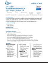
integrated management tools for the blade environment. As shown in Figure 1 below, the 16 PowerEdge
M610 blade servers used in this solution were divided into three ESXi clusters.
Figure 1 ESXi Blade Clusters on PowerEdge M1000e
These three clusters included:
• Infrastructure Cluster: Three M610 blade servers hosting virtual machines for Active Directory
services, VMware vCenter 5.0 Server, VMware View 5.1 Server (primary and secondary), Windows
Server 2008 R2 file server, SQL Server 2008R2, and 30 Login VSI launchers.
• Two View Clusters: One with eight M610 blade servers and another with five M610 blade servers,
because VMware View allows a maximum of eight servers in a non-NFS cluster.
The backplane of the blade chassis consisted of the following switches:
• Two PowerConnect M6220 blade switches in fabrics A1 and A2 for connectivity to a Management
LAN.
• Four PowerConnect M6348 bade switches in fabrics B1, B2, C1, and C2.

BP1033 Deploying VMware View 5.1 on VMware vSphere 5.0 U1 with Dell EqualLogic Storage
14
Switches in fabrics B1 and C1 were uplinked to a pair of Dell Force10 S55 switches for
dedicated access to the iSCSI SAN.
Switches in fabrics B2 and C2 were connected to the VDI LAN and provide client connectivity.
The three physical networks that allow for segregation of different types of traffic are:
• Management LAN: This network provides a separate management network for all the physical ESXi
hosts, network switches, and EqualLogic arrays. It also allows communication between various
infrastructure components such as Microsoft Active Directory server, Microsoft SQL Server
®
and
VMware vCenter server.
• Dedicated iSCSI SAN: Dedicated iSCSI storage area networking through which all the virtual desktops
and other infrastructure components access the EqualLogic storage.
• VDI LAN: This is the network over which the clients access the virtual desktops in the View desktop
pools.
For detailed information on how the Management LAN and VDI LAN were setup, please refer to Appendix
B.
3.2 iSCSI SAN configuration
Figure 2 shows the network connectivity between a single M610 blade server and the storage array
through the blade server chassis. The figure shows only one M610, though all 16 blades were used in the
testing. The topology is identical for all the remaining blades in the chassis.
• Each PowerEdge M610 server included two Broadcom NetXtreme
®
II 5709s quad-port NIC
mezzanine cards. One card was assigned to fabric B and the other to fabric C on the blade chassis.
• One NIC port from fabric B and one from fabric C are used to provide SAN connectivity. This also
ensures connectivity in case of mezzanine card failure. Additionally, one NIC port from each of
fabrics B and C are used to provide VDI LAN connectivity.
• Dual PowerConnect M6348 switches were installed in fabric B and fabric C on the blade server
chassis. The NIC mezzanine cards were internally connected to each of these switches through the
mid-plane on the blade server chassis.
• Two Force10 S55 switches were used for external SAN access. These switches were configured with
stacking modules and 10GbE SFP+ uplink modules in the expansion bays.
• The uplink modules were used to create 2 x 10GbE LAG uplinks to the PowerConnect M6348 blade
chassis switches.
• The stacking module was used to connect the two S55 switches together for failure resiliency and
ease of management.
• Each EqualLogic PS6100XS array has two controllers with four iSCSI network ports and one
Management port. Two ports on each storage controller were connected to one Force10 S55 switch
while the other two ports were connected to the other Force10 S55 switch. The management port
was connected to the PowerConnect 6248 switches on the Management LAN.
Note: For this white paper only two NIC ports per mezzanine card were used. Additional ports could be
used to provide additional bandwidth.

BP1033 Deploying VMware View 5.1 on VMware vSphere 5.0 U1 with Dell EqualLogic Storage
15
Figure 2 iSCSI SAN connectivity
3.3 EqualLogic storage array configuration
A single EqualLogic PS6100XS array hosted all the virtual desktops. The volume layout used for configuring
the Replica volumes and the VDI volumes on a single PS6100XS array is shown in Table 1.
Table 1 EqualLogic volume layout on single PS6100XS array
Volume Name Size Purpose
VDI-BaseImages 150GB Storage for Base image for VDI deployment
VDI-Replicas 150GB Storage for Replica images created by VMware View
VDI-Images1 500GB Storage for VDI Virtual Machines in View Cluster 1
VDI-Images2 500GB Storage for VDI Virtual Machines in View Cluster 1
VDI-Images3 500GB Storage for VDI Virtual Machines in View Cluster 1
VDI-Images4
500GB
Storage for VDI Virtual Machines in View Cluster 1
VDI-Images5 500GB Storage for VDI Virtual Machines in View Cluster 2
VDI-Images6 500GB Storage for VDI Virtual Machines in View Cluster 2
VDI-Images7 500GB Storage for VDI Virtual Machines in View Cluster 2
VDI-Images8 500GB Storage for VDI Virtual Machines in View Cluster 2
In addition to the PS6100XS array, a PS6500E array in a different pool provided a CIFS share for all the
virtual desktops through a Microsoft Windows
®
OS-based file server. This CIFS share was used to redirect
the user data and roaming profiles of the virtual desktops to a centralized location.

BP1033 Deploying VMware View 5.1 on VMware vSphere 5.0 U1 with Dell EqualLogic Storage
16
3.4 ESXi host network configuration
VMware ESXi 5.0 U1 hypervisor was installed on all 16 blades. The network configuration on each of those
hosts is described below. Each ESXi host was configured with three virtual switches: vSwitch0, vSwitch1,
and vSwitchISCSI to separate the different types of traffic on the system.
Table 2 vSwitch configuration in ESXi
vSwitch
Description
vSwitch0
Management Network
vSwitch1
VDI LAN
vSwitchISCSI
iSCSI SAN
For additional information on individual vSwitch configuration, refer to Appendix C.
3.5 VMware View configuration
View 5.1 was installed by following the documentation provided by VMware.
View 5.1 Documentation: http://pubs.vmware.com/view-51/index.jsp
Here are the specific configuration decisions used in the configuration:
• Two View servers were configured to provide load balancing and high availability.
• The View servers were installed as VMs on two separate hosts with two virtual CPUs, 10GB of RAM,
and 40GB virtual hard drive.
• The first View Server was installed as a “View Standard Server” during the installation, while the
second View Server was installed as a “View Replica Server”.
• View Composer was installed on the same VM as the vCenter server, even though View 5.1 provides
the option of installing it on a stand-alone VM. There was no difference found in performance with
either option.
• Self-signed SSL certificates were applied to the VMware vCenter server VM and View 5.1 server VMs.
3.6 VMware View Pool configuration
The Add pool wizard in View was used to choose the following specific configuration options to create the
virtual desktop pools.
• Virtual desktop pool type: Automated Pool
• User Assignment: Floating
• vCenter Server: View Composer linked clones
• View Composer Disks: Redirect disposable files to a non-persistent disk of size 4096MB
• Storage Optimization: Select separate datastores for replica and OS disk
• Advanced Storage Options: Use host caching
• Guest Customization: Sysprep
More information about View Pool configuration can be found in the VMware View 5.1 documentation:
http://pubs.vmware.com/view-51/topic/com.vmware.view.administration.doc/GUID-0A9CA985-3A78-
428A-BCFB-B3E2DCCA90AD.html

BP1033 Deploying VMware View 5.1 on VMware vSphere 5.0 U1 with Dell EqualLogic Storage
17
3.7 Windows 7 VM configuration
Following the guidelines from VMware and Login VSI, the Windows 7 base image was generated based on
a generic Base VM with the following properties.
• VMware Virtual hardware v8
• One virtual CPU
• 1.5GB RAM
• 25GB virtual hard drive
• One virtual NIC connected to vSwitch3
• Windows 7 64bit OS
Additionally, the base image was customized using VMware’s Optimization guide for Windows 7, available
here: http://www.vmware.com/files/pdf/VMware-View-OptimizationGuideWindows7-EN.pdf

BP1033 Deploying VMware View 5.1 on VMware vSphere 5.0 U1 with Dell EqualLogic Storage
18
4 View test methodology
This section outlines the test objectives along with the test tools and criteria used to determine the sizing
guidelines and best practices for deploying View on the EqualLogic storage platform.
4.1 Test objectives
• Develop best practices and sizing guidelines for a View 5.1 based VDI solution deployed on
EqualLogic PS series storage, Dell Force10 and PowerConnect switches, and Dell PowerEdge blade
servers with ESXi 5.0 as the server virtualization platform.
• Determine how many virtual desktops can be deployed in this environment using a single PS6100XS
array with acceptable user experience indicators for a task worker workload profile.
• Determine the performance impact on the storage array during peal I/O activity such as boot and
login storms.
4.2 Test approach
The key VDI use cases that were validated are:
• Task worker workload characterization
• Boot storms analysis
• Login storms and steady state analysis
All virtual desktops were restarted at the beginning of each login storm and steady state test to ensure they
were in a consistent state. Only non-persistent desktops were used where any changes made to the
desktop images are lost when the user logs off. However, changes to the user profiles were preserved by
storing them on a CIFS share serviced by a Microsoft Windows Server 2008 R2 file share server. This was
achieved through folder and profile redirection using Group Policy Objects (GPOs) on the Active Directory
server.
4.3 Test tools
All tests were conducted using Login VSI 3.6 as the workload generator. Login VSI, developed by Login
Consultants, is a widely adopted VDI benchmarking and load generation tool.
Login VSI is a unique benchmarking tool to measure the performance and scalability of centralized
desktop environments such as Server Based Computing (SBC) and Virtual Desktop Infrastructure (VDI).
More information can be found at: http://www.loginvsi.com
4.3.1 Load generation
The “Medium” workload from Login VSI was used to simulate the task worker workload. The
characteristics of the Medium workload are:
• Up to five applications are open simultaneously.
• Applications include Office, IE, Word, PDF, Power Point, Excel, 7-Zip.
• Once a session is started, the medium workload repeats every 12 minutes.
• During a loop, the response time is measured every two minutes.

BP1033 Deploying VMware View 5.1 on VMware vSphere 5.0 U1 with Dell EqualLogic Storage
19
• Idle time is about two minutes between each 12 minute loop.
• Type rate is approximately 160ms per character.
Although Login VSI provides other workloads, the Medium workload was used in the tests because it
closely resembles the workload of a task worker.
4.3.2 Monitoring tools
The following monitoring tools were used:
• Dell EqualLogic SAN Headquarters (SAN HQ) for monitoring storage array performance
• VMware vCenter Statistics for ESXi performance
• Login VSI Analyzer
• Liquidware Labs Stratusphere UX for user experience monitoring
• Custom script polling array counters for monitoring TCP retransmissions
Detailed performance metrics were captured from the storage arrays, hypervisors, virtual desktops, and
the load generators during the tests.
4.4 Test criteria
The primary focus of the tests was to determine the maximum number of desktops which can be
deployed using a single PS6100XS array in this environment while using VMware View Composer to
provide Linked Clone virtual desktops in an automated pool.
VDI configurations involve many components at different layers – application, hypervisor, network, and
storage. As a result, multiple metrics need to be monitored at different layers to ensure that the
environment is healthy and performing appropriately for all users.
The specific test criteria are described in the following sections.
4.4.1 Storage capacity and I/O latency
The typical industry standard latency limit for storage disk I/O is 20ms. Maintaining this limit ensures good
user application response times when there are no other bottlenecks at the infrastructure layer.
In addition to this, it is also recommended to maintain a 15% spare capacity on the storage array.
4.4.2 System utilization at the hypervisor
Even though the primary focus of these tests was storage characterization, additional metrics at the
hypervisor infrastructure layer were defined to ensure solution consistency. These are:
• CPU utilization on any ESXi server should not exceed 90%
• Minimal or no memory ballooning on ESXi servers
• Total network bandwidth utilization should not exceed 90% on any one link
• TCP/IP storage network retransmissions should be less than 0.5%
4.4.3 Virtual desktop user experience
The Liquidware Labs Stratusphere UX user experience metric was used to ensure that all desktops had
acceptable levels of application performance.

BP1033 Deploying VMware View 5.1 on VMware vSphere 5.0 U1 with Dell EqualLogic Storage
20
Liquidware Labs Stratusphere UX was used to gather data for user experience and desktop performance.
Data gathered from the hosts (in VMware vCenter) and the virtual machines (software installed on the VM)
is reported back to the Stratusphere Hub. The Stratusphere Hub was used to generate a comprehensive
report on the Desktop Virtualization Performance Analysis. This report includes information about the host
performance, virtual machine performance, and user performance. The report also provides a scatter plot
that shows the performance of all the users in the system.
Liquidware Labs Stratusphere UX can generate a variety of reports that compare and validate user
experience metrics. More information about these reports, including sample reports can be found here:
http://www.liquidwarelabs.com/products/stratusphere-ux-validation-reports.asp
The criteria for the scatter plot is shown below.
Figure 3 Liquidware criteria for the scatter plot
4.5 Test setup
Two virtual desktops pools were configured using the VMware View 5.1 Administrator. Each pool was built
from a Windows 7 base image. The Windows 7 configuration information is available in Section 3.7.
Desktop pool properties:
• Two View desktop pools
• Pool 1 with 512 virtual desktops (64 virtual desktops per host, eight hosts), spread across four 500 GB
volumes (VDI-Images 1 – 4)
• Pool 2 with 320 virtual desktops (64 virtual desktops per host, five hosts), spread across four 500GB
volumes (VDI-Images 5 – 8)
• Base images are stored on a separate 150GB volume (VDI-BaseImages)
• Replica images are stored on a separate 150GB volume (VDI-Replicas)
• Storage over-commit for all volumes was set to conservative
• View Composer disposable disk size was 4096 MB
• Disposable disk drive letter was set to auto
/