Moxa AWK-3131A-RTG Series User manual
- Category
- Routers
- Type
- User manual

Moxa AWK-3131A-RTG User’s Manual
Edition 1.0, December 2018
www.moxa.com/product
© 2018 Moxa Inc. All rights reserved.

Moxa AWK-3131A-RTG User’s Manual
The software described in this manual is furnished under a license agreement and may be used only in accordance with
the terms of that agreement.
Copyright Notice
© 2018 Moxa Inc. All rights reserved.
Trademarks
The MOXA logo is a registered trademark of Moxa Inc.
All other trademarks or registered marks in this manual belong to their respective manufacturers.
Disclaimer
Information in this document is subject to change without notice and does not represent a commitment on the part of
Moxa.
Moxa provides this document as is, without warranty of any kind, either expressed or implied, including, but not limited
to, its particular purpose. Moxa reserves the right to make improvements and/or changes to this manual, or to the
products and/or the programs described in this manual, at any time.
Information provided in this manual is intended to be accurate and reliable. However, Moxa assumes no responsibility for
its use, or for any infringements on the rights of third parties that may result from its use.
This product might include unintentional technical or typographical errors. Changes are periodically made to the
information herein to correct such errors, and these changes are incorporated into new editions of the publication.
Technical Support Contact Information
www.moxa.com/support
Moxa Americas
Toll
-free: 1-888-669-2872
Tel:
+1-714-528-6777
Fax:
+1-714-528-6778
Moxa China (Shanghai office)
Toll
-free: 800-820-5036
Tel:
+86-21-5258-9955
Fax:
+86-21-5258-5505
Moxa Europe
Tel:
+49-89-3 70 03 99-0
Fax: +49-89-3 70 03 99-99
Moxa Asia
-Pacific
Tel:
+886-2-8919-1230
Fax: +886-2-8919-1231
Moxa India
Tel:
+91-80-4172-9088
Fax:
+91-80-4132-1045

Table of Contents
1. Introduction ...................................................................................................................................... 1-1
Overview ........................................................................................................................................... 1-2
Package Checklist ............................................................................................................................... 1-2
Product Features ................................................................................................................................ 1-2
Product Specifications ......................................................................................................................... 1-3
Functional Design ............................................................................................................................... 1-3
LAN Port..................................................................................................................................... 1-3
LED Indicators ............................................................................................................................ 1-4
Beeper ....................................................................................................................................... 1-5
Reset Button ............................................................................................................................... 1-5
2. Getting Started.................................................................................................................................. 2-1
First-Time Installation and Configuration ............................................................................................... 2-2
Communication Testing ....................................................................................................................... 2-3
Function Map ..................................................................................................................................... 2-5
3. Web Console Configuration ............................................................................................................... 3-1
Web Browser Configuration .................................................................................................................. 3-3
Overview ........................................................................................................................................... 3-4
Basic Settings .................................................................................................................................... 3-5
System Info Settings ................................................................................................................... 3-5
Network Settings ......................................................................................................................... 3-6
Time Settings ............................................................................................................................. 3-8
Wireless Settings ................................................................................................................................ 3-9
Operation Mode ................................................................................................................................ 3-10
Basic Wireless Settings (Multiple SSID) ............................................................................................... 3-11
WLAN Security Settings.............................................................................................................. 3-13
Advanced Wireless Settings ........................................................................................................ 3-20
WLAN Certification Settings (Only For EAP-TLS in Client Mode) ....................................................... 3-25
WAC Settings (AP Mode Only) ..................................................................................................... 3-26
Advanced Settings ............................................................................................................................ 3-27
Using Virtual LAN ...................................................................................................................... 3-27
Configuring Virtual LAN .............................................................................................................. 3-28
DHCP Server ............................................................................................................................. 3-29
Packet Filters ............................................................................................................................ 3-31
Static Route (For Client-Router Mode Only) .................................................................................. 3-33
NAT Settings/Port Forwarding (For Client-Router Mode Only) .......................................................... 3-34
SNMP Agent.............................................................................................................................. 3-35
Mobile IP Settings ..................................................................................................................... 3-37
Link Fault Pass-Through (For Client Mode Only) ............................................................................ 3-38
Auto Warning Settings ....................................................................................................................... 3-39
System Log .............................................................................................................................. 3-39
Syslog ..................................................................................................................................... 3-40
E-mail ...................................................................................................................................... 3-41
Traps ....................................................................................................................................... 3-42
Status ............................................................................................................................................. 3-44
Wireless Status ......................................................................................................................... 3-44
Associated Client List (For AP Mode Only) ..................................................................................... 3-44
DHCP Client List ........................................................................................................................ 3-45
System Log .............................................................................................................................. 3-45
Relay Status ............................................................................................................................. 3-46
DI and Power Status .................................................................................................................. 3-46
AeroLink Protection Status (For Client Mode Only) ......................................................................... 3-46
Routing Table ........................................................................................................................... 3-47
LAN Status ............................................................................................................................... 3-47
Maintenance .................................................................................................................................... 3-47
Console Settings ....................................................................................................................... 3-47
Ping ......................................................................................................................................... 3-48
Firmware Upgrade ..................................................................................................................... 3-48
Config Import/Export ................................................................................................................. 3-49
Load Factory Default .................................................................................................................. 3-50
Username/Password .................................................................................................................. 3-50
Locate Device ........................................................................................................................... 3-50
Misc. Settings ........................................................................................................................... 3-51
Save Configuration ........................................................................................................................... 3-51
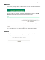
Restart ............................................................................................................................................ 3-52
Logout............................................................................................................................................. 3-52
4. Software Installation and Configuration ........................................................................................... 4-1
Overview ........................................................................................................................................... 4-2

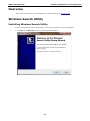
Wireless Search Utility ......................................................................................................................... 4-2
Installing Wireless Search Utility ................................................................................................... 4-2
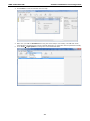
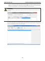
Configuring Wireless Search Utility ................................................................................................ 4-5
5. Using Other Consoles ........................................................................................................................ 5-1
USB Console Configuration (115200, None, 8, 1, VT100) ......................................................................... 5-2
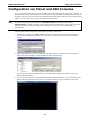
Configuration via Telnet and SSH Consoles ............................................................................................ 5-4
Configuration by Web Browser with HTTPS/SSL ...................................................................................... 5-5
Disabling Telnet and Browser Access ..................................................................................................... 5-6
A. References ........................................................................................................................................ A-1
Beacon .............................................................................................................................................. A-2
DTIM ................................................................................................................................................. A-2
Fragment ........................................................................................................................................... A-2
RTS Threshold .................................................................................................................................... A-2
STP and RSTP .................................................................................................................................... A-2
The STP/RSTP Concept ................................................................................................................ A-2
Differences Between RSTP and STP ............................................................................................... A-3
B. Supporting Information .................................................................................................................... B-1
Firmware Recovery ............................................................................................................................. B-2
DoC (Declaration of Conformity) ........................................................................................................... B-3
Federal Communication Commission Interference Statement ............................................................ B-3
RED Compliance Statement .......................................................................................................... B-3
Canada, Industry Canada (IC) Notices ........................................................................................... B-4
Antenna Gain and RF Radiated Power ............................................................................................ B-5
R&TTE Compliance Statement ....................................................................................................... B-7

1
1. Introduction
The AWK-3131A-RTG series wireless AP/client is the wireless solution for railway train-to-ground applications
such as CCTV and CBTC communications. It can provide speeds of up to 300 Mbps with IEEE 802.11n
technology. The AWK-3131A-RTG series can operate at temperatures ranging from -25 to 60°C for standard
models and -40 to 75°C for extended temperature models, and is rugged enough for rolling stock environments.
Installation is easy, with either DIN-rail mounting or distribution boxes, and the DIN-rail mounting capability,
wide operating temperature range, and IP30 housing with LED indicators make the AWK-3131A-RTG a
convenient yet reliable solution for any rolling stock application.
The following topics are covered in this chapter:
Overview
Package Checklist
Product Features
Product Specifications
Functional Design
LAN Port
LED Indicators
Beeper
Reset Button

AWK-3131A-RTG UM Introduction
1-2
Overview
The AWK-3131A-RTG is 802.11n compliant to deliver speed, range, and reliability to support even the most
bandwidth-intensive applications. The 802.11n standard incorporates multiple technologies, including MIMO
(Multi-In, Multi-Out) Spatial Multiplexing, multiple channels (5, 10, 20 and 40 MHz), and dual bands (2.4 GHz
and 5 GHz) to achieve high speeds, while still being able to communicate with legacy 802.11a/b/g devices.
The AWK-3131A-RTG is compliant with the EN 50155 standard that covers operating temperature range,
power input voltage, surge, ESD, and vibration. The AWK-3131A-RTG can be easily mounted on to a wall, DIN
rail or in distribution boxes. Its wide operating temperature range, IP68-rated housing with LED indicators, and
the DIN-rail mounting capability make the AWK-3131A-RTG a convenient yet reliable solution for all types of
industrial wireless applications.
Package Checklist
Moxa’s AWK-3131A-RTG is shipped with the following items. If any of these items is missing or damaged,
please contact your customer service representative for assistance.
• 1 AWK-3131A-RTG
• 1 DIN-rail kit
• 2 plastic RJ45 protective cap: One for the console port and the other for use as a backup
• 1 plastic protective cap for fiber port (AWK-3131A-SSC-RTG only)
• Cable holder with one screw
• Quick installation guide (printed)
• Warranty card
NOTE
Antennas are not included and s
hould be purchased separately. The AWK is certified with 2dBi omni-
directional
antennas with QMA to RP
-SMA adapters.
Product Features
• Designed specifically for the wireless communication requirements in train-to-ground communication (e.g.:
CBTC and CCTV).
• 2x2 MIMO technology
• M12 anti-vibration connectors (AWK-3131A-M12-RTG)
• SC optical fiber connection (AWK-3131A-SSC-RTG)
• -40 to 75°C operating temperature range (T models)
• Certified against the EN 50121-4 railway standard
• Complies with all EN 50155 mandatory test items*
• Controller-based Turbo Roaming (handover time < 50 ms @ 3 channels, WPA2) - available only when used
with the WAC-1001 or WAC-2004
• Supports 5.8 GHz band in the standard model
• Supports QoS function, which can help assign high priority to your critical traffic
• Provides advanced wireless security settings
• Provides 64-bit and 128-bit WEP/WPA/WPA2 encryption
• SSID Hiding, IEEE 802.1X security, and RADIUS
• Packet access control and filtering
• Supports SNMP, SNTP, SSH, HTTPS, TFTP for remote management
• Wall mountable
• Long-distance transmission support

AWK-3131A-RTG UM Introduction
1-3
There are many factors that affect the performance of a device when it is used in long-distance applications.
These factors include:
• Test architecture
• Installation distance
• Car speed
• Antenna gain
• Band
• Transmission Power
• Signal Strength
• Channel interference
For details, please contact your Moxa sales representative.
Product Specifications
NOTE
The latest specifications for Moxa’s products can be found at
https://www.moxa.com.
ATTENTION
•
The AWK-3131A-RTG is NOT a portable mobile device and should be located at least
20 cm away from the
human body.
•
The AWK-3131A-
RTG is NOT designed for the general public. To establish a wireless network safely using
the AWK-3131A-RTG, a well-trained technician should be consulted for installation.
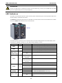
Functional Design
LAN Port
The standard model of the AWK-3131A-RTG is provided with one M12 D code Megabit port. The LAN LED will
light up when you insert the cable in the LAN port and a connection is established.
The standard model of AWK-3131A-SSC-RTG is provided with one SC fiber port. The 100M LED will light up
when you insert the cable in the SC fiber port and a connection is established.

AWK-3131A-RTG UM Introduction
1-4
ATTENTION
Do not use
a PoE (Power over Ethernet) Injector for the PoE device(s). Instead, use an IEEE 802.3af or IEE
E
802.3at compliant PSE (Power Sourcing Equipment).
LED Indicators
The LEDs on the front panel provide a quick and easy means of determining the current operational status and
wireless settings of the AWK-3131A-RTG.
The FAULT LED indicates system failures. If the AWK-3131A-RTG cannot retrieve the IP address from a DHCP
server, the FAULT LED will blink at one-second intervals.
The following table summarizes how to read the device’s wireless settings based on the LED displays. More
information is available in Chapter 3 in the “Basic Wireless Settings” section.
LED Color State Description
PWR1 Green
On Power is being supplied from power input 1.
Off Power is not being supplied from power input 1.
PWR2 Green
On Power is being supplied from power input 2.
Off Power is not being supplied from power input 2.
PoE
(AWK-3131A-
M12-RTG only)
Amber
On Power is being supplied via PoE.
Off
Power is not being supplied via PoE.
FAULT Red
Blinking
(slow at 1-second
intervals)
Cannot get an IP address from the DHCP server
Blinking
(fast at 0.5-second
intervals)
IP address conflict
Off No errors
STATE
Green/
Red
Green
System startup is complete and the system is in operation
Green (blinking at
1-second intervals)
The AWK has been located by the Wireless Search Utility.
Red Boot up error
SIGNAL
(5 LEDs)
Green
On Signal level
(for Client and Client-Router mode only)
Off
CLIENT MODE Green
On
The AWK is functioning in Client or Client-Router Mode.
Off
The AWK is not functioning in Client or Client-Router
Mode.

AWK-3131A-RTG UM Introduction
1-5
LED Color State Description
WLAN Amber
On WLAN is in use.
Off WLAN is not in use.
LAN/
100M*
Green
On 100 Mbps link is active.
Blinking Data is being transmitted at 100 Mbps.
Off 100 Mbps link is inactive.
ATTENTION
When the
system fails to boot, the LEDs for STATE (Green), FAULT, and WLAN will all light up
simultaneously and blink at one
-second intervals. This may be due to improper operation or issues
such as an
unexpected shutdown while updating the firmware. To recover th
e firmware, refer to the “Firmware
Recovery” section in
Appendix B Supporting Information.
Beeper
The beeper emits two short beeps when the system is ready.
Reset Button
The Reset button is located on the bottom panel of the AWK-3131A-RTG. You can reboot the AWK-3131A-RTG
or reset it to factory default settings by pressing the Reset button with a pointed object such as an unfolded
paper clip.
• System reboot: Hold the Reset button down for under 5 seconds and then release.
• Reset to factory default: Hold the Reset button down for over 5 seconds until the STATE LED starts
blinking green light. Release the button to reset the AWK-3131A-RTG.

2
2. Getting Started
This chapter explains how to install Moxa’s AirWorks AWK-3131A-RTG for the first time to quickly set up your
wireless network and how to test whether the connection is working well. The function map provided in Chapter
3 is a convenient reference to the various functions available on the AWK-3131A-RTG and to determine the
functions that you need to use.
The following topics are covered in this chapter:
First-Time Installation and Configuration
Communication Testing
Function Map

AWK-3131A-RTG UM Getting Started
2-2
First-Time Installation and Configuration
Before installing the AWK-3131A-RTG, make sure that all items mentioned in the package checklist are in the
box. You will also need access to a notebook computer or PC equipped with an Ethernet port. The
AWK-3131A-RTG has a default IP address that you must use when connecting to the device for the first time.
• Step 1: Select the power source.
The AWK-3131A-RTG can be powered by a DC power input or PoE (Power over Ethernet).
• Step 2: Connect the AWK-3131A-RTG to a notebook or PC.
Since the AWK-3131A-RTG is provided with the MDI/MDI-X auto-sensing capability, you can use either a
straight-through cable or crossover cable to connect it to a computer. When the connection between the
AWK-3131A-RTG and the computer is established, the LED indicator on the AWK-3131A-RTG’s LAN port
lights up.
• Step 3: Set up the computer’s IP address.
Set an IP address for the computer so that it is on the same subnet as that of the AWK-3131A-RTG. Since
the AWK-3131A-RTG’s default IP address is 192.168.127.253, and the subnet mask is 255.255.255.0,
set the IP address of the computer in the 192.168.127.xxx IP range and subnet mask to 255.255.255.0.
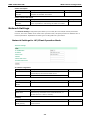
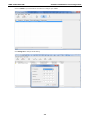
• Step 4: Use the web-based manager to configure the AWK-3131A-RTG
Open your computer’s web browser and type http://192.168.127.253 in the address field to access the
homepage of the web-based Network Manager. Before the homepage opens, you will need to enter the user
name and password as shown in the following figure. For first-time configuration, enter the following
default user name and password and click on the Login button:
User Name: admin
Password: moxa
NOTE
For security reasons, we strongly recommend changing the default password. To
change the password,
select
Maintenance
Password and follow the instructions on the screen.
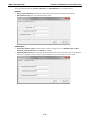
NOTE
After you click
Submit to apply changes, the web page is refreshed and an (Updated)
indicator is displayed
next to the page heading along with a blinking reminder to restart the device.
To activate the changes
, click Restart and then click Save and Restart after you change the settings.
The
AWK
-3131A-RTG will take about 30 seconds to complete the reboot process.

AWK-3131A-RTG UM Getting Started
2-3
• Step 5: Select the operation mode for the AWK-3131A-RTG.
By default, the operation mode of the AWK-3131A-RTG is set to AP. You can change this setting to Client
mode at Wireless Settings WLAN Basic Wireless Settings. Detailed information about configuring
the AWK-3131A-RTG is available in Chapter 3.
• Step 6: Test the network connection.
In the following sections we describe two methods that you can use to test that a network connection has
been established.
Communication Testing
After installing the AWK-3131A-RTG you can run a sample test to make sure the wireless connection on the
AWK-3131A-RTG is functioning normally. Two testing methods are described below. Use the first method if you
are using only one AWK-3131A-RTG device and the second method if you are using two or more
AWK-3131A-RTG units.
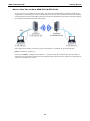
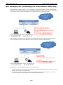
How to Test One AWK-3131A-RTG
If you are only using one AWK-3131A-RTG, you will need one additional notebook computer equipped with a
WLAN card. Configure the WLAN card to connect to the AWK-3131A-RTG (NOTE: the default SSID is MOXA),
and change the IP address of the second notebook (Notebook B) so that it is on the same subnet as the first
notebook (Notebook A), which is connected to the AWK-3131A-RTG.
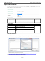
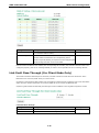
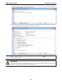
After configuring the WLAN card, establish a wireless connection with the AWK-3131A-RTG and open a DOS
window on Notebook B. At the prompt, type the following:
ping <IP address of notebook A>
and then press Enter (see the figure below). A “Reply from IP address …” response means the communication
was successful. A “Request timed out.” response means the communication failed. In this case, recheck the
configuration to make sure the connections are correct.

AWK-3131A-RTG UM Getting Started
2-4
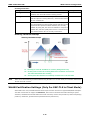
How to Test Two or More AWK-3131A-RTG Units
If you have two or more AWK-3131A-RTG units, you will need a second notebook computer (Notebook B)
equipped with an Ethernet port. Use the default settings for the first AWK-3131A-RTG connected to notebook
A and change the second or third AWK-3131A-RTG connected to notebook B to Client mode, and then configure
the notebooks and AWK-3131A-RTG units properly.
After setting up the testing environment, open a DOS window on notebook B. At the prompt type:
ping <IP address of notebook A>
and then press Enter. A “Reply from IP address …” response means the communication was successful. A
“Request timed out” response means the communication failed. In the latter case, recheck the configuration to
make sure the settings are correct.

AWK-3131A-RTG UM Getting Started
2-5
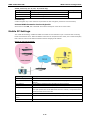
Function Map
Basic settings for administering the
AWK-3131A-M12-RTG
Current status information for monitoring
wired/wireless network performance, advanced
services, and device management functions
Functions for maintaining the AWK-3131A-M12-RTG,
and for diagnosing the network
On-demand functions to support the web-based
console management operation
Quick overview of the AWK-3131A-M12-RTG’s
status
Essential settings related to establishing a wireless
network
Advanced features to support additional network
management and secure wired and wireless
communication
Note: These advanced functions are all optional
Application-oriented device management
functions to set up events, traps, and reactions via
e-mail and SNMP notifications
Note: These functions are all optional

3
3. Web Console Configuration
In this chapter, we explain all aspects of web-based console configuration. Moxa’s easy-to-use management
functions help you set up your AWK-3131A-RTG and make it easy to establish and maintain your wireless
network.
The following topics are covered in this chapter:
Web Browser Configuration
Overview
Basic Settings
System Info Settings
Network Settings
Time Settings
Wireless Settings
Operation Mode
Basic Wireless Settings (Multiple SSID)
WLAN Security Settings
Advanced Wireless Settings
WLAN Certification Settings (Only For EAP-TLS in Client Mode)
WAC Settings (AP Mode Only)
Advanced Settings
Using Virtual LAN
Configuring Virtual LAN
DHCP Server
Packet Filters
NAT Settings/Port Forwarding (For Client-Router Mode Only)
SNMP Agent
Mobile IP Settings
Link Fault Pass-Through (For Client Mode Only)
Auto Warning Settings
System Log
Syslog
E-mail
Traps
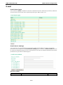
Status
Wireless Status
Associated Client List (For AP Mode Only)
DHCP Client List
System Log
Relay Status
DI and Power Status

AWK-3131A-RTG UM Web Console Configuration
3-2
AeroLink Protection Status (For Client Mode Only)
Routing Table
LAN Status
Maintenance
Console Settings
Ping
Firmware Upgrade
Config Import/Export
Load Factory Default
Username/Password
Locate Device
Misc. Settings
Save Configuration
Restart
Logout

AWK-3131A-RTG UM Web Console Configuration
3-3
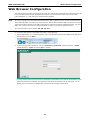
Web Browser Configuration
The web interface provides a convenient way to modify the configuration of the AWK-3131A-RTG and access its
built-in monitoring and network administration functions. The recommended web browser is Microsoft
®
Internet Explorer 11.0 with JVM (Java Virtual Machine) installed.
NOTE
To use the management and monitoring functions
of the AWK-3131A-RTG from a PC host connected t
o the
same LAN as the
AWK-3131A-RTG, you must make sure that the PC host and the AWK-3131A-RTG
are on the
same logical subnet. Similarly, if the
AWK-3131A-RTG is configured on a different VLAN than the PC,
you must
make sure your PC host is on the manageme
nt VLAN so that it can access the AWK-3131A-RTG.
The default IP
address of the AWK is 192.168.127.253.
To access the web interface of the AWK-3131A-RTG, do the following:
1. Open a web browser (e.g., Internet Explorer), type in the default IP address of the AWK-3131A-RTG in the
address field, and press Enter.
2. In the login page that is displayed, enter the Username and Password (default Username = admin;
default Password = moxa) and click Login to continue.
You may need to wait a few moments for the main page to download to your computer. Note that the model
name and IP address of the AWK-3131A-RTG are both shown in the title bar of the web page. You can
identify the web interfaces of multiple AWK-3131A-RTG units using this information.

AWK-3131A-RTG UM Web Console Configuration
3-4
3. Use the menu tree on the left side of the window to open the configuration pages for the AWK-3131A-RTG’s
functions.
In the following paragraphs, we describe each AWK-3131A-RTG management function in detail. An overview of
all the functions is available in the “Function Map” section of this manual.
NOTE
The model name of the
AWK-3131A-RTG is shown as AWK-3131A-RTG-
XX, where XX indicates the country
code. The
model name indicates the AWK-3131A-RTG version and the bandwidth it uses. We use
AWK
-3131A-RTG-US as an example in the following figures. (The country code and model name that
appears on your computer screen may be different.)
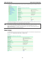
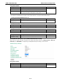
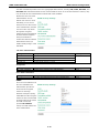
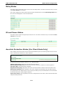
Overview
The Overview page summarizes the AWK-3131A-RTG’s current status. The information is categorized into the
following groups: System Info, Device Info, and 802.11 Info.

AWK-3131A-RTG UM Web Console Configuration
3-5
Click on the SSID (MOXA, in this case) to display detailed information on 802.11as shown below:
NOTE
The
802.11 Info that is displayed may differ based on the operation mode selected. For example, Current
B
SSID is not available in Client mode, and Signal strength/Noise Floor is not available in AP mode.
Basic Settings
The Basic Settings group includes the most commonly used settings required by administrators to maintain
and control the AWK-3131A-RTG.
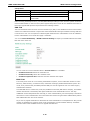
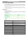
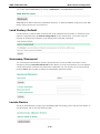
System Info Settings
The System Info related settings that you configure here, especially the Device name and Device
description, are displayed on the Overview page. They are also included in the SNMP information and email
alerts. Configuring the System Info settings for each AWK-3131A-RTG makes it easier to identify the different
AWK-3131A-RTG units connected to your network.
Device name
Format Description Factory Default
Maximum of 31
characters
Specifies the role or application of this AWK-3131A-RTG
unit.
AWK-3131A-RTG_<Serial
No. of this
AWK-3131A-RTG>
Device location
Format Description Factory Default
Maximum. of 31
characters
Specifies the location of this AWK-3131A-RTG unit. None

AWK-3131A-RTG UM Web Console Configuration
3-6
Device description
Format Description Factory Default
Maximum of 31
characters
You can use this space to record a more detailed
description of this AWK-3131A-RTG
None
Device contact information
Format Description Factory Default
Maximum of 31
characters
You can use this space to record the
contact information of the
person responsible for maintaining this AWK-3131A-RTG.
None
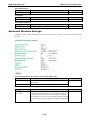
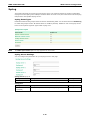
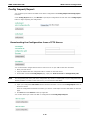
Network Settings
The Network Settings configuration panel allows you to modify the usual TCP/IP network parameters.
However, due to the addition of the client-router operation mode, this panel provides two different sets of
network parameters. Explanations for both types of configuration are given below.
Network Settings for AP/Client Operation Mode
IP address assignment
Setting Description Factory Default
DHCP The AWK-3131A-RTG’s IP address will be assigned
automatically by the network’s DHCP server
Static
Static Set up the AWK-3131A-RTG’s IP address manually.
IP address
Setting Description Factory Default
AWK-3131A-RTG’s IP
address
Identifies the AWK-3131A-RTG on a TCP/IP network. 192.168.127.253
Subnet mask
Setting Description Factory Default
AWK-3131A-RTG’s
subnet mask
Identifies the type of network to which the AWK-3131A-RTG
is
connected (e.g., 255.255.0.0 for a Class B network, or
255.255.255.0 for a Class C network).
255.255.255.0
Gateway
Setting Description Factory Default
AWK-3131A-RTG’s
default gateway
The IP address of the router that connects the LAN to an
outside network.
None
Page is loading ...
Page is loading ...
Page is loading ...
Page is loading ...
Page is loading ...
Page is loading ...
Page is loading ...
Page is loading ...
Page is loading ...
Page is loading ...
Page is loading ...
Page is loading ...
Page is loading ...
Page is loading ...
Page is loading ...
Page is loading ...
Page is loading ...
Page is loading ...
Page is loading ...
Page is loading ...
Page is loading ...
Page is loading ...
Page is loading ...
Page is loading ...
Page is loading ...
Page is loading ...
Page is loading ...
Page is loading ...
Page is loading ...
Page is loading ...
Page is loading ...
Page is loading ...
Page is loading ...
Page is loading ...
Page is loading ...
Page is loading ...
Page is loading ...
Page is loading ...
Page is loading ...
Page is loading ...
Page is loading ...
Page is loading ...
Page is loading ...
Page is loading ...
Page is loading ...
Page is loading ...
Page is loading ...
Page is loading ...
Page is loading ...
Page is loading ...
Page is loading ...
Page is loading ...
Page is loading ...
Page is loading ...
Page is loading ...
Page is loading ...
Page is loading ...
Page is loading ...
Page is loading ...
Page is loading ...
Page is loading ...
Page is loading ...
Page is loading ...
Page is loading ...
Page is loading ...
Page is loading ...
Page is loading ...
Page is loading ...
Page is loading ...
Page is loading ...
Page is loading ...
Page is loading ...
Page is loading ...
-
 1
1
-
 2
2
-
 3
3
-
 4
4
-
 5
5
-
 6
6
-
 7
7
-
 8
8
-
 9
9
-
 10
10
-
 11
11
-
 12
12
-
 13
13
-
 14
14
-
 15
15
-
 16
16
-
 17
17
-
 18
18
-
 19
19
-
 20
20
-
 21
21
-
 22
22
-
 23
23
-
 24
24
-
 25
25
-
 26
26
-
 27
27
-
 28
28
-
 29
29
-
 30
30
-
 31
31
-
 32
32
-
 33
33
-
 34
34
-
 35
35
-
 36
36
-
 37
37
-
 38
38
-
 39
39
-
 40
40
-
 41
41
-
 42
42
-
 43
43
-
 44
44
-
 45
45
-
 46
46
-
 47
47
-
 48
48
-
 49
49
-
 50
50
-
 51
51
-
 52
52
-
 53
53
-
 54
54
-
 55
55
-
 56
56
-
 57
57
-
 58
58
-
 59
59
-
 60
60
-
 61
61
-
 62
62
-
 63
63
-
 64
64
-
 65
65
-
 66
66
-
 67
67
-
 68
68
-
 69
69
-
 70
70
-
 71
71
-
 72
72
-
 73
73
-
 74
74
-
 75
75
-
 76
76
-
 77
77
-
 78
78
-
 79
79
-
 80
80
-
 81
81
-
 82
82
-
 83
83
-
 84
84
-
 85
85
-
 86
86
-
 87
87
-
 88
88
-
 89
89
-
 90
90
-
 91
91
-
 92
92
-
 93
93


Moxa AWK-3131A-RTG Series User manual
- Category
- Routers
- Type
- User manual
Ask a question and I''ll find the answer in the document
Finding information in a document is now easier with AI
Related papers
-
Moxa A-CAP-N-M Specification
-
 Moxa Technologies AWK-3131A-RTG Series Quick Install Guide
-
 Moxa Technologies AWK-3131A-M12-RTG Quick Install Guide
-
-
-
Moxa ICS-G7826A Series User manual
-
-
Moxa ICS-G7826A Series User manual
-
 Moxa Technologies IEX-408E-2VDSL2 series User manual
-


Other documents
-
Linksys WPC54G User manual
-
Trendnet TEW-510APB User manual
-
Alfa Network AWAP803 User manual
-
 Foxit WAC Server User manual
-
SmartDream POPPOP User manual
-
Tenda i9 User guide
-
 Moxa Technologies AirWorks AWK-3121-M12-RTG Quick Installation Manual
-
LevelOne WAP-0007 User manual
-
Moxa Technologies Switch EDS-726 User manual
-
HP Integrity NonStop Troubleshooting Tips Service and Maintain

