Page is loading ...

DMCI
DigitalMedia™ Card Interface
Installation Guide
Hardware Hookup
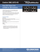
Make the necessary connections to the rear panel of the DMCI as called out in the
following illustration. Apply power after all connections have been made.
DMCI Rear Panel Connections
Description
The Crestron
®
DMCI is a compact device designed to support a variety of interface
functions using any DMC Series input card. With a complete range of input cards
available, the DMCI can be used to convert virtually any type of AV signal to an HDMI
®
signal. The DMCI can equip an HDMI switcher to accept other types of inputs, or it can
add an HDMI output to an analog AV switcher. The DMCI can even be used to create a
custom DigitalMedia™ receiver or streaming decoder. Integrating the DMCI with a
Crestron control system via a Cresnet
®
connection allows detailed AV signal information to
be viewed on a touch screen and allows for CEC signal routing.
Installation
Install a DMC input card into the DMC input card slot of the DMCI. Then, install the DMCI
into a rack, under a table, or on a at surface.
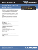
Installing a DMC Input Card
CAUTION: The DMCI is powered by the 4-position terminal block connector labeled
NET. Before installing or removing an input card, ensure that the DMCI is not
powered on. The DMC input cards are not hot swappable.
CAUTION: Cards are static sensitive. When handling cards, follow standard
electrostatic discharge precautions.
CAUTION: To avoid damaging the pins on the bottom of the card, use care when
inserting the card into the DMCI.
To install a DMC input card into the input card slot of the DMCI, do the following:
1. Using caution to avoid damage to the pins on the bottom of the card, insert the card
into the guides of the input card slot until the card is 1/4 inch from the fully seated
position.
2. Align the two thumb screws of the card with the corresponding holes in the DMCI
chassis, and then push the card inward until it is fully seated and engages the
chassis backplane.
3. Finger-tighten the two thumb screws to secure the card—do not overtighten the
screws.
Installing a DMC Input Card into the DMCI
Additional Resources
Visit the product page on the Crestron website (www.crestron.com)
for additional information and the latest rmware updates. Use a QR
reader application on your mobile device to scan the QR image.
LAN Port and Pinout Table
NOTE: The LAN port is intended only for computer console (for example, a rmware
upgrade) and for the communication of USB HID signals over an Ethernet connection.
Unlike many other Crestron products, this LAN port should not be used for program
control.
PIN Signal PIN Signal
1 TX + 5 N/C
2 TX - 6 RX -
3 RX + 7 N/C
4 N/C 8 N/C
Mounting into a Rack or onto a Rack Rail
The DMCI can be mounted into a rack or onto a rack rail:
• To mount the DMCI into a rack, use the Crestron ST-RMK Rack Mount Kit (sold
separately). For additional information, refer to the ST-RMK Rack Mount Kit
Installation Guide (Doc. 5664).
• To mount the DMCI onto a rack rail, use the Crestron UTK-1U-HALF Under-Table
Mounting Kit (sold separately). For additional information, refer to the UTK-1U-HALF
Under-Table Mounting Kit Installation Guide (Doc. 7621).
Mounting under a Table
The DMCI can be mounted under a table using the Crestron UTK-1U-HALF Under-Table
Mounting Kit (sold separately). For additional information, refer to the UTK-1U-HALF
Under-Table Mounting Kit Installation Guide (Doc. 7621).
Mounting onto a Flat Surface
The DMCI can be placed on a at surface or stacked with other equipment. Four feet are
factory installed on the DMCI to provide stability when the unit is placed on a at surface
or stacked.
Green
LED
Yellow
LED
PIN 8 PIN 1
NET:
To Control System
and Other Cresnet Devices
DMC Input Card Slot:
Install cards to receive input signals
from audio, video, and PC sources.
LAN:
10BASE-T/100BASE-TX
Computer Console
and USB HID Extension

As of the date of manufacture, this product has been tested and found to comply with specications
for CE marking.
Federal Communications Commission (FCC) Compliance Statement
This device complies with part 15 of the FCC rules. Operation is subject to the following conditions:
(1) this device may not cause harmful interference, and (2) this device must accept any interference
received, including interference that may cause undesired operation.
CAUTION: Changes or modications not expressly approved by the manufacturer responsible for
compliance could void the user’s authority to operate the equipment.
NOTE: This equipment has been tested and found to comply with the limits for a Class B digital
device, pursuant to part 15 of the FCC rules. These limits are designed to provide reasonable
protection against harmful interference in a residential installation. This equipment generates, uses and
can radiate radio frequency energy and if not installed and used in accordance with the instructions,
may cause harmful interference to radio communications. However, there is no guarantee that
interference will not occur in a particular installation. If this equipment does cause harmful interference
to radio or television reception, which can be determined by turning the equipment off and on, the
user is encouraged to try to correct the interference by one or more of the following measures:
• Reorient or relocate the receiving antenna.
• Increase separation between the equipment and the receiver.
• Connect the equipment inot an outlet on a circuit different from that to which the receiver is
connected.
• Consult the dealer or an experienced radio/TV technician for help.
Rack Mounting Safety Precautions
Elevated Operating Ambient Temperature: If the unit is installed in a closed or multiunit rack assembly,
the operating ambient temperature of the rack environment may be greater than room ambient
temperature. Therefore, consideration should be given to installing the equipment in an environment
compatible with the maximum ambient temperature (Tma) specied by the manufacturer.
Reduced Airow: Installation of the equipment in a rack should be such that the amount of airow
required for safe operation of the equipment is not compromised.
Crestron Electronics, Inc. Installation Guide - DOC. 6852B
15 Volvo Drive Rockleigh, NJ 07647 (2024732)
Tel: 888.CRESTRON 02.16
Fax: 201.767.7576 Specications subject to
www.crestron.com change without notice.
Mechanical Loading: Mounting of the equipment in the rack should be such that a hazardous
condition is not achieved due to uneven mechanical loading.
Circuit Overloading: Consideration should be given to the connection of the equipment to the supply
circuit and the effect that overloading of the circuits might have on overcurrent protection and supply
wiring. Appropriate consideration of equipment nameplate ratings should be used when addressing
this concern.
Reliable Earthing: Reliable earthing of rack-mounted equipment should be maintained. Particular
attention should be given to supply connections other than direct connections to the branch circuit
(e.g., use of power strips).
The product warranty can be found at www.crestron.com/warranty.
The specic patents that cover Crestron products are listed at patents.crestron.com.
Certain Crestron products contain open source software. For specic information, please visit
www.crestron.com/opensource.
Crestron, the Crestron logo, Cresnet, and DigitalMedia are either trademarks or registered trademarks
of Crestron Electronics, Inc. in the United States and/or other countries. HDMI, the HDMI logo, and
High Denition Multimedia Interface are either trademarks or registered trademarks of HDMI Licensing
LLC in the United States and/or other countries. Other trademarks, registered trademarks, and trade
names may be used in this document to refer to either the entities claiming the marks and names or
their products. Crestron disclaims any proprietary interest in the marks and names of others. Crestron
is not responsible for errors in typography or photography.
This document was written by the Technical Publications department at Crestron.
©2016 Crestron Electronics, Inc.
/