Page is loading ...
WWW.GRIZZLY.COM
CONTRACTOR GRADE AIR COMPRESSORS
MODEL G8297/G8298/G8299
INSTRUCTION MANUAL
COPYRIGHT © 1999 BY GRIZZLY INDUSTRIAL, INC.
1821 VALENCIA ST., BELLINGHAM, WA 98227
WARNING: NO PORTION OF THIS MANUAL MAY BE REPRODUCED IN ANY SHAPE
OR FORM WITHOUT THE WRITTEN APPROVAL OF GRIZZLY INDUSTRIAL, INC.


G8297/G8298/G8299 Air Compressors
-1-
Table Of Contents
PAGE
1. SAFETY
SAFETY RULES FOR POWER TOOLS ..........................................................2-3
ADDITIONAL SAFETY INSTRUCTIONS FOR AIR COMPRESSORS................4
2. CIRCUIT REQUIREMENTS
110V OPERATION ..............................................................................................5
GROUNDING ......................................................................................................5
EXTENSION CORDS ..........................................................................................5
3. INTRODUCTION
COMMENTARY....................................................................................................6
UNPACKING ........................................................................................................7
SITE CONSIDERATIONS ....................................................................................7
PREPARING FOR USE ......................................................................................8
4. OPERATIONS
GENERAL ............................................................................................................9
STARTING ........................................................................................................10
PRESSURE REGULATOR ................................................................................10
CONNECTING TOOLS ......................................................................................11
5. MAINTENANCE
EACH USE ........................................................................................................12
AFTER FIRST 50 HOURS ................................................................................13
WEEKLY ............................................................................................................13
EVERY 300 HOURS ..........................................................................................13
PRESSURE LIMIT ADJUSTMENT ....................................................................14
6. CLOSURE................................................................................................................15
PARTS BREAKDOWN AND PARTS LISTS................................................................16-20
TROUBLESHOOTING ......................................................................................................21
WARRANTY AND RETURNS ..........................................................................................22

-2-
G8297/G8298/G8299 Air Compressors
Safety Instructions For Power Tools
SECTION 1: SAFETY
5. KEEP CHILDREN AND VISITORS
AWAY. All children and visitors should be
kept a safe distance from work area.
6. MAKE WORK SHOP CHILD PROOF with
padlocks, master switches, or by removing
starter keys.
7. DON’T FORCE TOOL. It will do the job
better and safer at the rate for which it was
designed.
8. USE RIGHT TOOL. Don’t force tool or
attachment to do a job for which it was not
designed.
1. KEEP GUARDS IN PLACE and in working
order.
2. REMOVE ADJUSTING KEYS AND
WRENCHES. Form habit of checking to
see that keys and adjusting wrenches are
removed from tool before turning on.
3. KEEP WORK AREA CLEAN. Cluttered
areas and benches invite accidents.
4. DON’T USE IN DANGEROUS ENVIRON-
MENT. Don’t use power tools in damp or
wet locations, or where any flammable or
noxious fumes may exist. Keep work area
well lighted.
For Your Own Safety Read Instruction
Manual Before Operating This Equipment
Indicates an imminently hazardous situation which, if not
avoided, WILL result in death or serious injury.
Indicates a potentially hazardous situation which, if not
avoided, COULD
result in death or serious injury.
Indicates a potentially hazardous situation which, if not
avoided, MAY
result in minor or moderate injury. It may also
be used to alert against unsafe practices.
This symbol is used to alert the user to useful information
about proper operation of the equipment.
The purpose of safety symbols is to attract your attention to possible hazardous conditions.
This manual uses a series of symbols and signal words which are intended to convey the level
of importance of the safety messages. The progression of symbols is described below.
Remember that safety messages by themselves do not eliminate danger and are not a substi-
tute for proper accident prevention measures.
NOTICE

G8297/G8298/G8299 Air Compressors
-3-
9. USE PROPER EXTENSION CORD. Make
sure your extension cord is in good condi-
tion. Conductor size should be in accor-
dance with the chart below. The amperage
rating should be listed on the motor or tool
nameplate. An undersized cord will cause a
drop in line voltage resulting in loss of
power and overheating. Your extension
cord must also contain a ground wire and
plug pin. Always repair or replace exten-
sion cords if they become damaged.
Minimum Gauge for Extension Cords
10. WEAR PROPER APPAREL. Do not wear
loose clothing, gloves, neckties, rings,
bracelets, or other jewelry which may get
caught in moving parts. Non-slip footwear
is recommended. Wear protective hair cov-
ering to contain long hair.
11. ALWAYS USE SAFETY GLASSES. Also
use face or dust mask if cutting operation is
dusty. Everyday eyeglasses only have
impact resistant lenses, they are NOT safe-
ty glasses.
12. SECURE WORK. Use clamps or a vise to
hold work when practical. It’s safer than
using your hand and frees both hands to
operate tool.
LENGTH
AMP RATING 25ft 50ft 100ft
0-6 18 16 16
7-10 18 16 14
11-12 16 14 12
13-16 14 12 12
17-20 12 12 8
21-30 10 10 No
Safety Instructions For Power Tools
13. DON’T OVERREACH. Keep proper foot-
ing and balance at all times.
14. MAINTAIN TOOLS WITH CARE. Keep
tools sharp and clean for best and safest
performance. Follow instructions for lubri-
cating and changing accessories.
15. DISCONNECT TOOLS before servicing
and changing accessories, such as blades,
bits, cutters, and the like.
16. REDUCE THE RISK OF UNINTENTION-
AL STARTING. Make sure switch is in off
position before plugging in.
17. USE RECOMMENDED ACCESSORIES.
Consult the owner’s manual for recom-
mended accessories. The use of improper
accessories may cause risk of injury.
18. CHECK DAMAGED PARTS. Before fur-
ther use of the tool, a guard or other part
that is damaged should be carefully
checked to determine that it will operate
properly and perform its intended function.
Check for alignment of moving parts, bind-
ing of moving parts, breakage of parts,
mounting, and any other conditions that
may affect its operation. A guard or other
part that is damaged should be properly
repaired or replaced.
19. NEVER LEAVE TOOL RUNNING UNAT-
TENDED. TURN POWER OFF. Don’t
leave tool until it comes to a complete stop.
-4-
Additional Safety Instructions For Air
Compressors
1. Operate the compressor in a well-ventilated
area free of acids, vapor, explosive gases
and flammable or unstable materials.
2. Use compressor only with air, never use
with any other type of gas.
3. Never aim the air nozzle directly at yourself
or others. The air stream can be quite force-
ful and can damage skin.
4. Do not pull on rubber hoses to move the
compressor.
5. Do not use compressed air for filling breath-
ing or diving apparatus. Compressed air
from this compressor cannot be used for
pharmaceutical, food or health require-
ments without further treatment.
6. Never transport the compressor under pres-
sure. Always make sure the pressure in the
storage tanks has been released before
loading or moving the air compressor.
7. Never attempt to adjust the pressure safety
valve on the air tanks. This is preset to 150
PSI.
Operating this equipment has the potential
to propel debris into the air which can
cause eye injury. Always wear safety glass-
es or goggles when operating equipment.
Everyday glasses or reading glasses only
have impact resistant lenses, they are not
safety glasses. Be certain the safety glass-
es you wear meet the appropriate stan-
dards of the American National Standards
Institute (ANSI).
Like all power tools, there is danger asso-
ciated with the operation of air compres-
sors. Accidents are frequently caused by
lack of familiarity or failure to pay attention.
Use this equipment with respect and cau-
tion to lessen the possibility of operator
injury. If normal safety precautions are
overlooked or ignored, serious personal
injury may occur.
No list of safety guidelines can be com-
plete. Every shop environment is different.
Always consider safety first, as it applies to
your individual working conditions. Use
this and other machinery with caution and
respect. Failure to do so could result in
serious personal injury, damage to equip-
G8297/G8298/G8299 Air Compressors
-5-
110V Operation
SECTION 2: CIRCUIT REQUIREMENTS
If you find it necessary to use an extension cord
with your compressor, make sure the cord is
rated Hard Service (grade S) or better. Refer to
the chart in the standard safety instructions to
determine the minimum gauge for the extension
cord. The extension cord must also contain a
ground wire and plug pin. Always repair or
replace extension cords when they become worn
or damaged.
Extension Cords
Grounding
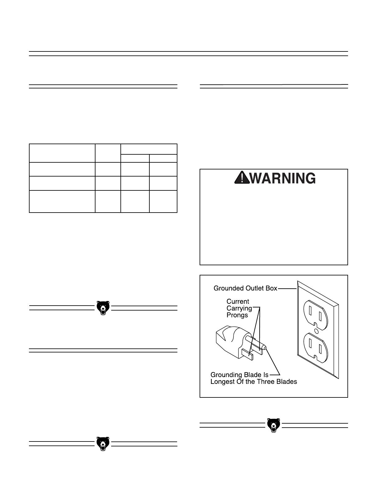
This equipment must be grounded. Verify
that any existing electrical outlet and circuit
you intend to plug into is actually ground-
ed. If it is not, it will be necessary to run a
separate 12 A.W.G. copper grounding wire
from the outlet to a known ground. Under
no circumstances should the grounding pin
from any three-pronged plug be removed.
Serious injury may occur.
In the event of an electrical short, grounding
reduces the risk of electric shock by providing a
path of least resistance to disperse electric cur-
rent. These machines are equipped with power
cords having an equipment-grounding conductor.
See Figure 1. The outlet must be properly
installed and grounded in accordance with all
local codes and ordinances.
This family of air compressors is wired for
110/120V, single phase operation only. The chart
below shows the maximum amperage draw and
recommended fusing level for each of the
machines.
Figure 1. Grounded plug configuration.
G8297
G8298
G8299 (2 Motors)
2.0
2.5
2.5
2.0
11
17
17
11
15
20
20
15
Model
Amperage
HP
Max
Fuse
It is generally best to operate a compressor on a
dedicated circuit, i.e. a circuit where there are no
other electrical appliances plugged in. The dual
motors on the G8299 should be plugged into sep-
arate circuits. The fuse requirements above
assume the use of a circuit breaker or a slow-
blow fuse. If an unusual load does not exist and
the compressor still breaks the circuit, contact a
qualified electrician or our service department.
-6-
G8297/G8298/G8299 Air Compressors
SECTION 3: INTRODUCTION
We are proud to offer the Grizzly Models
G8297/8298/8299 Contractor Grade Air
Compressors. These compressors are part of the
growing Grizzly family of heavy-duty machinery
for the contractor and professional user. When
used according to the guidelines set forth in this
manual, you can expect years of trouble-free,
enjoyable operation and proof of Grizzly’s com-
mitment to customer satisfaction.
These compressors are designed to suit the
needs of the professional contractor who requires
a reliable air source on the job site. The G8297 is
a 2.0 HP unit with a 4.25 gallon tank capacity and
delivers 4.2 CFM@90 PSI. The G8298 is similar
to the G8297 with the 2.5 HP motor which pro-
vides 5.8 CFM. The dual motor 4.5 HP G8299
delivers 10 CFM with a 9.0 gallon tank capacity.
The G8299 is conveniently portable with a wheel
built into the tank system.
We are also pleased to provide this manual with
your new air compressor. It was written to guide
you through assembly, review safety considera-
tions, and cover general operating procedures. It
represents our effort to produce the best docu-
mentation possible. If you have any comments
regarding this manual, please write to us at the
address below:
Grizzly Industrial, Inc.
C
/
O Technical Documentation
P.O. Box 2069
Bellingham, WA 98227-2069
Most importantly, we stand behind our machines.
If you have any service questions or parts
requests, please call or write us at the location
listed below.
Grizzly Industrial, Inc.
1203 Lycoming Mall Circle
Muncy, PA 17756
Phone: (570) 546-9663
Fax: (800) 438-5901
E-Mail: [email protected]
Web Site: http://www.grizzly.com
The specifications, drawings, and photographs
illustrated in this manual represent the Models
G8297/8298/8299 as supplied when the manual
was prepared. However, owing to Grizzly’s policy
of continuous improvement, changes may be
made at any time with no obligation on the part of
Grizzly. Whenever possible, though, we send
manual updates to all owners of a particular tool
or machine. Should you receive one, we urge you
to insert the new information with the old and
keep it for reference.
To operate this, or any power tool, safely
and efficiently, it is essential to become as
familiar with its characteristics as possible.
The time you invest before you begin to use
your air compressor will be time well spent.
DO NOT operate this machine until you are
completely familiar with the contents of this
manual. Make sure you read and under-
stand all of the safety procedures. If you do
not understand something, DO NOT operate
the machine.
Commentary

-7-
Unpacking
This air compressor is shipped from the manu-
facturer in a carefully packed carton. If you dis-
cover the machine is damaged after you’ve
signed for delivery, and the truck and driver are
gone, you will need to file a freight claim with the
carrier. Save the containers and all packing mate-
rials for possible inspection by the carrier or its
agent. Without the packing materials, filing a
freight claim can be difficult. If you need assis-
tance determining whether you need to file a
freight claim, or with the procedure to file one,
please contact our Customer Service.
When taking the air compressor to a job site, the
most important consideration is access to an
adequate and properly fused power supply. Refer
to Section 2: Circuit Requirements for the needs
for your particular compressor.
Also make sure the compressor is not operating
in an environment where there are any explosive,
flammable or caustic fumes or gases. A clear and
well-ventilated area is best for its safe operation.
Place the compressor on a solid and level sur-
face. Make sure that the hoses you attach to sup-
ply your pneumatic device will be unrestricted in
movement and not subject to being run over by
vehicles or punctured by any other sharp objects
in the area.
And since air compressors are often used for a
sustained period of time, sometimes in restricted
areas, it is also best to wear ear protection to
avoid the long-term exposure to the sound of the
electric motor and piston.
NOTICE
The machine should always be run in the
positions shown on the cover of this manu-
al. Never run the G8299 when it is standing
upright on its wheel and support frame.
Also never continue to operate the machine
if it has fallen over on its side. The motor
will not receive adequate oil flow in these
positions, and continued operation can

-8-
Before using your Grizzly Air Compressor, follow
these steps before the first use:
1. Remove all packing materials and the pro-
tective plastic plugs from the cylinder head
and oil plug. Do not remove the yellow cap
underneath the black plastic cover of the
pressure switch housing.
2. Screw the air filter(s) into the cylinder
head(s).
3. Place the oil dipstick into the opening of the
casing and check the oil level in the motor
crankcase. See Figure 2. Each motor
requires approximately 100 cc or 3.5 fluid
ounces of compressor oil (ISO 100 or SAE
30W viscosity, non-detergent). Make cer-
tain the oil is at the full indicator level on the
dipstick.
Operating this equipment has the potential
to propel debris into the air which can
cause eye injury. Always wear safety glass-
es or goggles when operating equipment.
Everyday glasses or reading glasses only
have impact resistant lenses, they are not
safety glasses. Be certain the safety glass-
es you wear meet the appropriate stan-
dards of the American National Standards
Institute (ANSI).
Operating this equipment has the potential
for hearing damage to occur, especially if
operated for a long period of time. Use
ANSI (American National Standards
Institute) approved ear muff or ear plugs
when using this equipment. Always wear
proper hearing protection, cotton balls or
tissue paper in the ear canal do not provide
adequate noise reduction.
Fig 2. Oil sump and dipstick.
4. Make sure drain valve(s) on the air tanks is
closed.
5. Make sure the power switch is in the OFF
position, fully pushed in. Connect the power
cord(s) to a properly protected power
source.
NOTICE
The machine should never be run without a
full oil reservoir. The oil provides lubrica-
tion to the cylinder rings which deliver the
compressed air. Severe damage to the
internal parts can occur if there is not ade-
quate oil flow. Check the oil level frequent-
ly, and change the oil on a regular sched-
G8297/G8298/G8299 Air Compressors
-9-
SECTION 4: OPERATIONS
The pump produces compressed air which goes
into the air tanks through the delivery pipe and
the check valve. When the air pressure arrives at
the factory pre-set level of 135 PSI, the pressure
switch shuts off the electrical current to the axial
electric pump. At the time it shuts off, it dis-
charges the air held in the pump cylinder to the
delivery pipe. This allows the pump to be depres-
surized so it can easily restart. When the pres-
sure in the air tanks falls below the minimum fac-
tory set pressure of 105 PSI, the pump cycles
again to build the pressure back up. The pressure
switch is supplied with a discharge valve with
delayed closing, which reduces the strain on the
pump and the motor during startup.
The compressor is operating correctly when there
is a bleed of air every time the motor is switched
off. You will notice an audible air discharge each
time the pump motor stops. On these compres-
sors, the pump will cycle first to minimize the
amperage draw and will bleed off air through the
cold-start valve. The valve will stay open until
approximately 20 PSI is reached in the air tanks
at which time it closes to allow full pressurization
of the tanks.
For the G8299 with the dual motors, both motors
can be started simultaneously for rapid pressur-
ization. As with the G8298, the 2.5 HP pump is fit-
ted with a cold-start valve which will stay open
until approximately 20 PSI is reached in the
tanks. This will allow the compressor to lubricate
properly without straining the motor and pump.
Depending on the volume of the air usage, it is
often adequate to recharge the system during
operation using only the 2 HP pump taking
advantage of its lower RPM and quieter opera-
tion.
General
Fig 3. Pressure safety relief valve.
All of the compressors are equipped with a 150
PSI safety relief valve which will discharge air
from the tanks if for any reason they should
become over-pressured. See Figure 3. These
are preset valves and are not adjustable.
Relief Valve
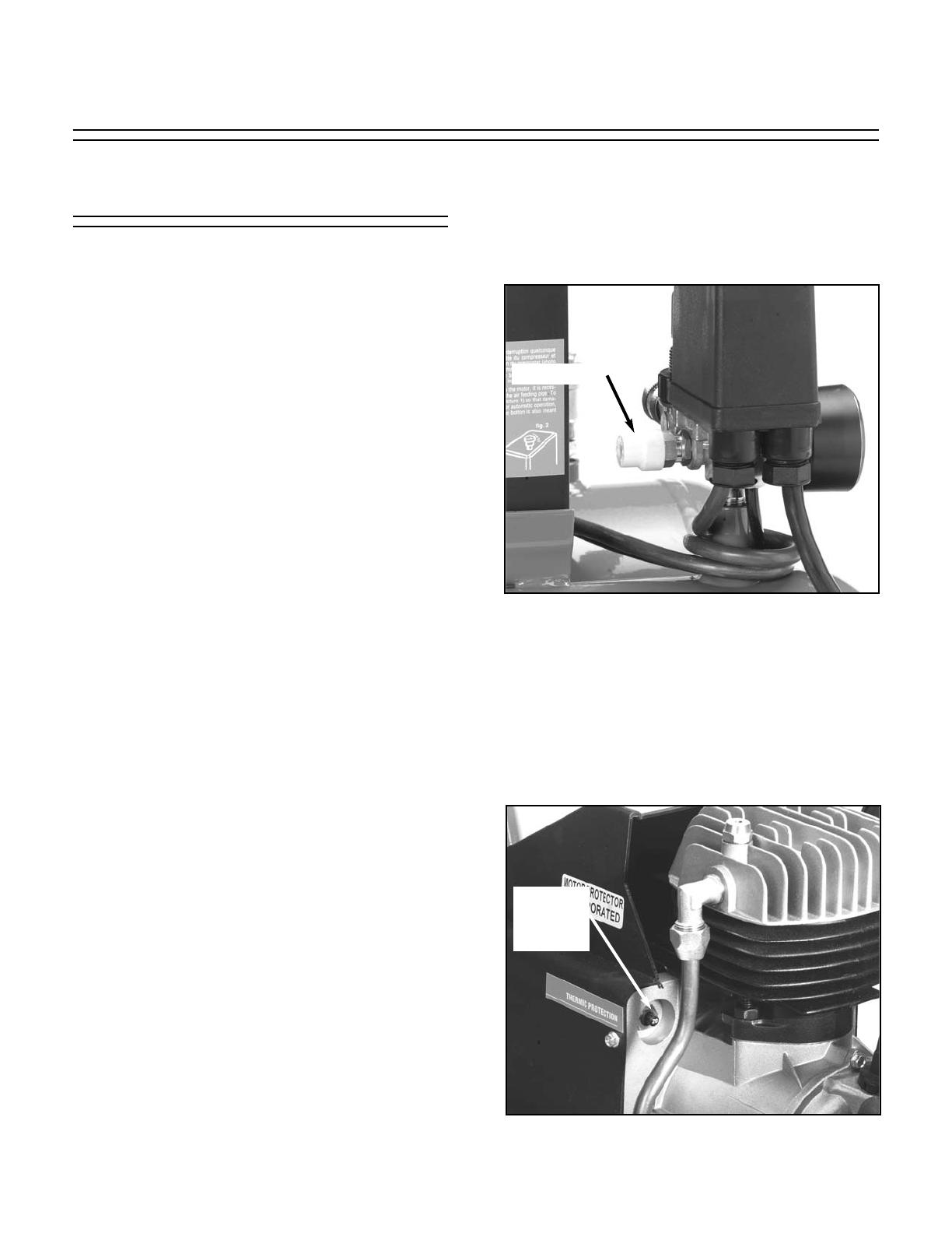
Fig 4. Thermal protection typical placement.
Thermal
Overload
Switch
These compressors are also equipped with ther-
mal overload breakers which will trip if there is
excessive load on the motors which causes a
heat buildup. In the event the breaker shuts the
compressor down, wait a few minutes for the unit
to cool down, then press the reset button shown
in Figure 4.
-10-
G8297/G8298/G8299 Air Compressors
After the compressor has fully pressurized the
tanks, turn the red knob on the pressure regula-
tor (See Figure 6) to set the pressure needed for
the air tool you will be using. Consult the manual
which accompanied your air tool to determine
what pressure setting is required for optimal oper-
ation. The gauge on the regulator will indicate the
pressure which will be delivered through the air
line.
Pressure Regulator
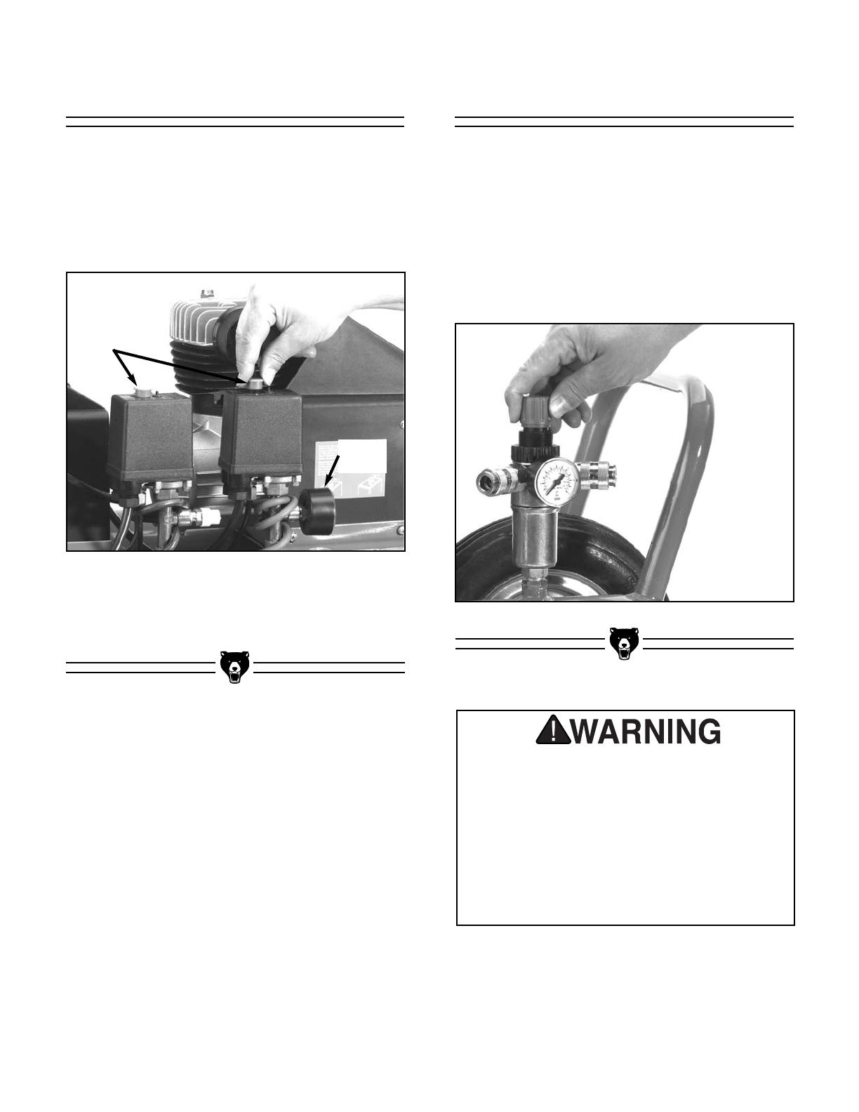
Make sure the compressor switch is in the OFF
position (the red button on top of the control box
should be in the fully depressed position, see
Figure 5) before connecting to the power supply.
Close the drain cock on the tanks. Pull the switch
to the ON position.
Starting
Fig 5. G8299 starting switches and gauge.
Check the tank pressure gauge to see that the
tank pressure gets up to approximately 120-130
PSI.
Tank
Gauge
On/Off
Switches
Fig 6. Pressure regulator and gauge.
Always wear safety glasses and use
extreme caution when working around
compressed air. The force of the air stream
can cause small bits of debris to become
airborne and cause potential injury to the
eyes or other parts of the body. Never let
the full force of the air stream come in
direct contact with the skin as it can cause
abrasions or bruising.
G8297/G8298/G8299 Air Compressors
-11-
Make sure the compressor model you use has
sufficient cubic feet per minute (CFM) output for
the air tool you plan to connect. Most air tools will
have an air requirement stated in terms of a spe-
cific CFM at a specific pressure (PSI). Most com-
mon is a rating at 90 PSI. Consult the chart below
to determine the output of your compressor
model.
Connecting Tools
Notes
G8297
G8298
G8299
2.0
2.5
4.5
4.2
5.8
10
4.25 gal
4.25 gal
9.0 gal
Model
HP
CFM
@ 90 PSI
Tank
Cap.
The compressor should put out a higher CFM
than the tool requires. If connecting multiple tools
which will be used simultaneously, then the CFM
for each tool should be added together and com-
pared to the compressor output value.
Consideration should also be given to the type of
usage. A nailer or staple gun uses air in short
bursts and it is easier for the compressor to main-
tain pressure. A paint sprayer or grinder tends to
use a more continuous stream of air as these
tools are run for longer time periods. It is always
better to oversize a compressor to allow for vari-
ation in the type of usage and the number of tools
to be powered. Air tools being operated with
insufficient air volume will not perform their func-
tion satisfactorily.
Connect the tool using a good quality air line with
an adequate length to reach from the compressor
to the point of use. Quick-connect couplers are a
good option for fast and sure connection of tools
and air hoses. Make certain the air hose will not
be placed in a position where it can become con-
stricted or cut by a sharp object. Having a hose
run over by heavy vehicles may not cause an
immediate leak, but it will shorten the life of the
hose.
G8297/G8298/G8299 Air Compressors
SECTION 5: MAINTENANCE
Regular periodic maintenance on your Air
Compressor will ensure its optimum perfor-
mance. Make a habit of inspecting your compres-
sor each time you use it. Check the following
items:
1. Check oil level. See Figure 7.
Each Use
Fig 7. Checking oil level with dipstick.
-12-
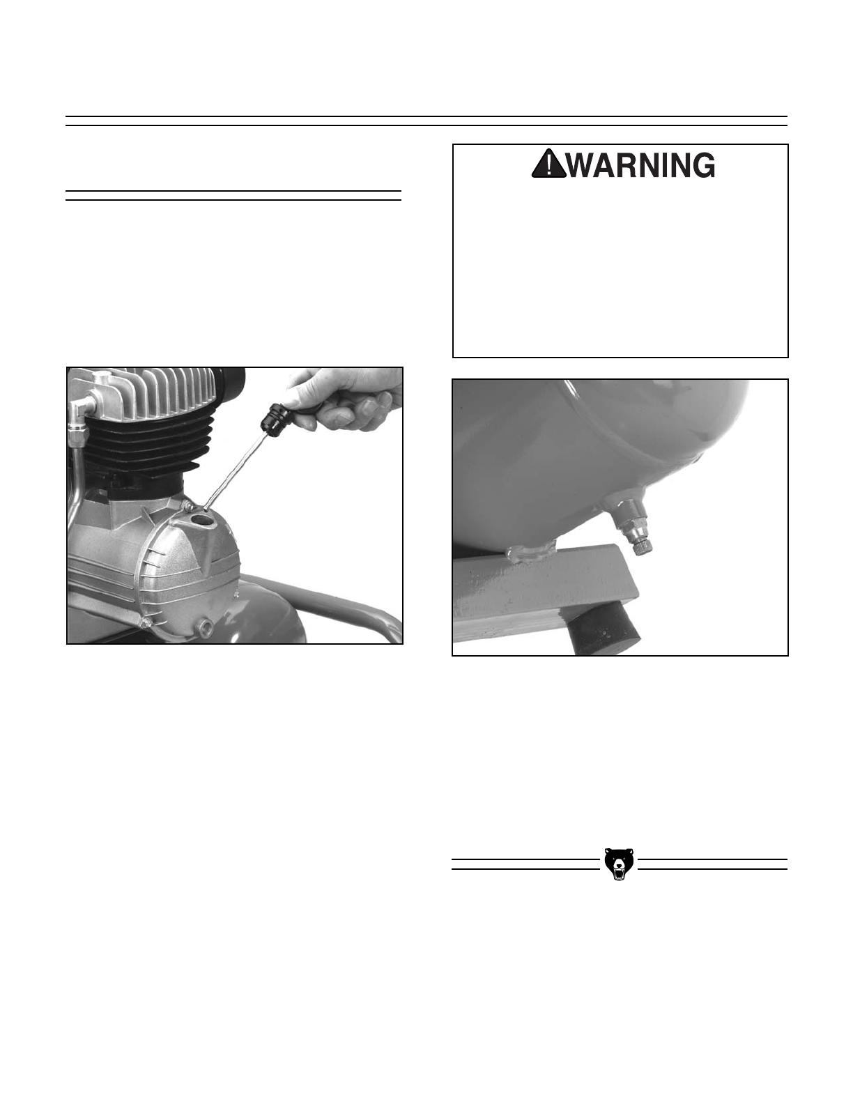
Fig 8. Typical location of drain cocks.
2. Drain tanks of any condensation by open-
ing the drain cocks on the bottom of both
tanks. See Figure 8. Depending upon the
amount of use and the weather conditions,
a certain amount of condensed water may
be released. For longevity of the compres-
sor seals and the air tools you connect, it is
best to keep the tanks free of water. The
tanks are best drained if the drain cocks are
opened when the system is pressurized.
Once water has stopped coming out, you
can close the drain cocks.
3. Clean off cylinder head cooling fins of any
dirt which might hamper air flow.
4. Check for worn or damaged cords and
plugs.
5. Check for any other condition that could
hamper the safe operation of this machine.
Always wear safety glasses and use
extreme caution when working around
compressed air. The force of the air stream
can cause small bits of debris to become
airborne and cause potential injury to the
eyes or other parts of the body. Never let
the full force of the air stream come in
direct contact with the skin as it can cause
abrasions or bruising.

G8297/G8298/G8299 Air Compressors
-13-
Weekly
Every 300 Hours
If the compressor is used on a regular daily basis,
perform the following checks each week:
1. Rinse the air filter foam element in water.
2. Check for loose bolts or fittings.
After every 300 hours or 3 months of regular
operation, perform the following maintenance
items:
1. Change compressor motor oil.
2. Rinse the air filter foam element in water.
3. Check for air leaks and correct as needed.
4. Clean cylinder head fins for proper cooling.
5. Check for loose bolts or fittings.
After First 50 Hours
After the first 50 working hours, or 30 days,
whichever comes first, replace the oil in the
motor with compressor oil (use ISO 100 or SAE
30W viscosity, non-detergent type).
Also after this initial operation period, check to
make sure that all the fittings are tight. Remove
the air filter foam element (See Figure 9) and
rinse it out in water. Allow it to dry and reinstall.
Blow out any accumulated dirt between the cylin-
der cooling fins.
Fig 9. Air filter cover and foam element.
Do not remove the pressure switch cover
with the machine plugged in to power.
When the cover is off, the electrical con-
nections are uncovered and can be a
source of electrical shock. Make the adjust-
ments progressively until the desired level
is reached, and disconnect from power
each time you turn the adjusting nut.
Serious personal injury can occur.
-14-
G8297/G8298/G8299 Air Compressors
Pressure Limit
Adjustment
The compressor is delivered with pressure switch
settings which turn the compressor pump off
when it reaches a tank pressure of 135 PSI, and
turn it back on when it reaches 105 PSI. Normally
these settings should not require any adjustment.
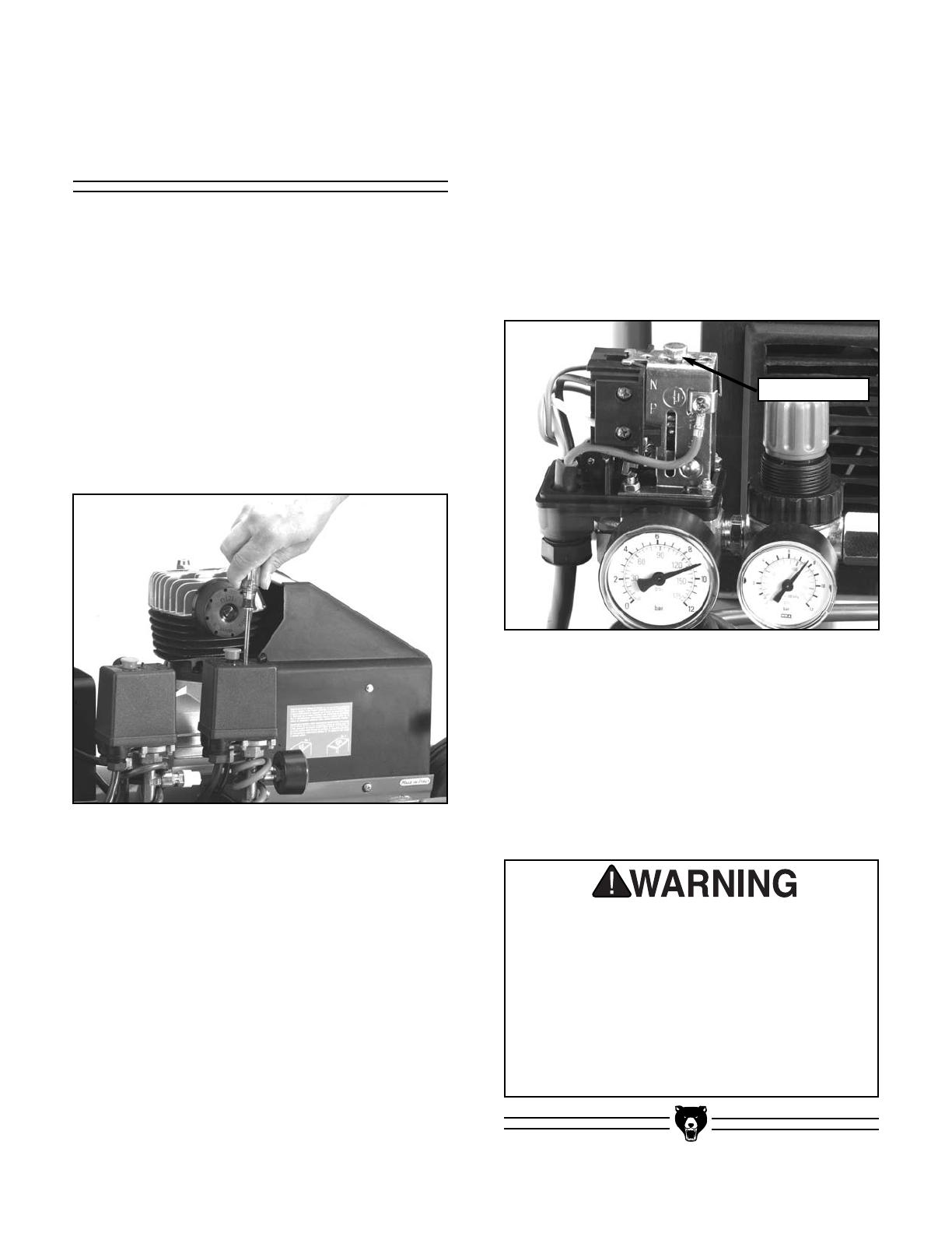
In the event it becomes necessary to change, first
make certain the compressor is disconnected
from the power source. Then remove the black
plastic cover below the On/Off switch. This is
done by removing the rubber plug on top of the
housing and inserting a Phillips
®
screwdriver. See
Figure 10.
Fig 10. Removing pressure switch cover.
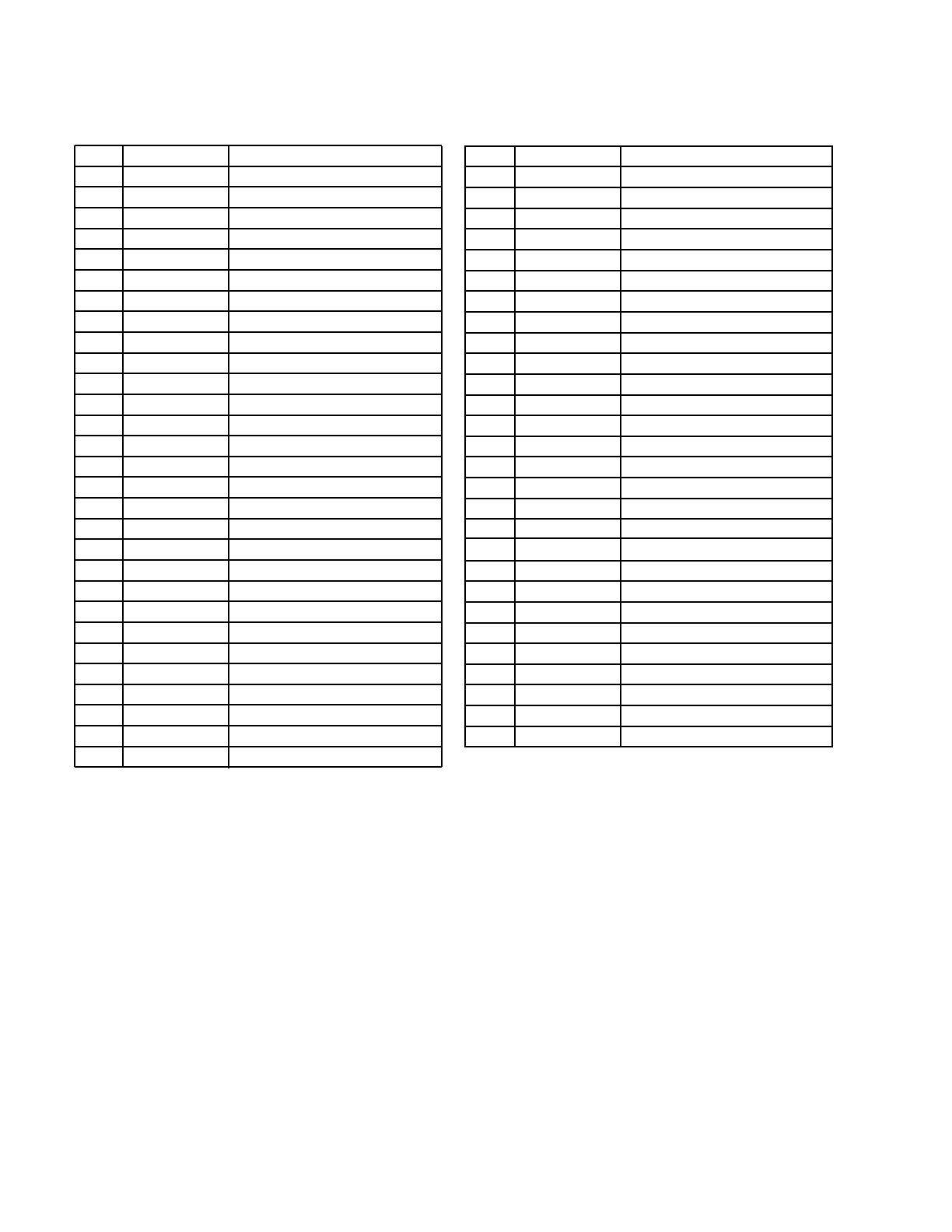
The hex nut on the top of the exposed switch is
used to adjust the pressure limits. See Figure 11.
Turn it clockwise to increase the pressure and
counterclockwise to reduce. This will move both
the maximum pressure shutoff point and the min-
imum pressure turn-on point simultaneously.
These limits are not separately adjustable. Do not
exceed a maximum cutoff pressure of 145 PSI.
After adjusting, replace the cover and reconnect
to the power source.
Fig 11. Adjusting nut on pressure switch.
Adjusting Nut
For the G8299, it is possible to control which
motor comes on first by adjusting these pressure
limits. The machine is set from the factory so the
2 HP pump comes on first to minimize amperage
draw. If this is not acceptable, adjust the limits on
the 2 HP higher, and set the limits on the 2.5 HP
lower so they will operate in reverse of the facto-
ry setting.

G8297/G8298/G8299 Air Compressors
-15-
The following pages contain general machine
data, parts diagrams/lists, troubleshooting guide
and Warranty/Return information for your Model
G8297/8298/8299 Air Compressor.
If you need parts or help in assembling your
machine, or if you need operational information,
we encourage you to call our Service
Department. Our trained service technicians will
be glad to help you.
If you have comments dealing specifically with
this manual, please write to our Bellingham,
Washington location using the address in Section
3 Introduction. The specifications, drawings, and
photographs illustrated in this manual represent
the Model G8297/8298/8299 Air Compressor as
supplied when the manual was prepared.
However, due to Grizzly’s policy of continuous
improvement, changes may be made at any time
with no obligation on the part of Grizzly.
Whenever possible, though, we send manual
updates to all owners of a particular tool or
machine. Should you receive one, add the new
information to this manual and keep it for refer-
ence.
We have included some important safety mea-
sures that are essential to this machine’s opera-
tion. While most safety measures are generally
universal, Grizzly reminds you that each work-
shop is different and safety rules should be con-
sidered as they apply to your specific situation.
We recommend you keep a copy of our current
catalog for complete information regarding
Grizzly's warranty and return policy. If you need
additional technical information relating to this
machine, or if you need general assistance or
replacement parts, please contact the Service
Department listed in Section 3: or Introduction.
Additional information sources are necessary to
realize the full potential of this machine. Trade
journals, woodworking magazines, and your local
library are good places to start.
SECTION 6: CLOSURE
The Model G8297/8298/8299 Air Compressors
are specifically designed for air tool operation.
DO NOT MODIFY AND/OR USE THIS
MACHINE FOR ANY OTHER PURPOSE.
Modifications or improper use of this tool
will void the warranty. If you are confused
about any aspect of this machine, DO NOT use
it until you have answered all your questions.
Serious personal injury may occur.
Like all power tools, there is danger asso-
ciated with operating this equipment.
Accidents are frequently caused by lack of
familiarity or failure to pay attention. Use
this tool with respect and caution to lessen
the possibility of operator injury. If normal
safety precautions are overlooked or
ignored, serious personal injury may
occur.
Operating this equipment has the potential
for flying debris to cause eye injury.
Always wear safety glasses or goggles
when operating equipment. Everyday
glasses or reading glasses only have
impact resistant lenses, they are not safety
glasses. Be certain the safety glasses you
wear meet the appropriate standards of the
American National Standards Institute
(ANSI).
-16-
G8297/G8298/G8299 Air Compressors
001 P8297001 Guard
002 P8297002 Screw M4.2 x 13
003 P8297003 Motor Flange
004 P8297004 Fan 155mm Dia.
005 P8297005 Screw M6 x 135
006 P8297006 Bearing 17 x 40 x 12
007 P8297007 Rotor
008 P8297008 Bearing 25 x 52 x 15
009 P8297009 Stator
010 P8297010 Compressor Casing
011 P8297011 Screw M8 x 35
012 P8297012 Screw M8 x 25
013 P8297013 Eccentric
014 P8297014 Connecting Rod
015 P8297015 Snap Ring 15mm
016 P8297016 Gasket
017 P8297017 Screw M4.2 x 13mm
018 P8297018 Casing Cover
019 P8297019 Oil Dipstick
020 P8297020 Piston 50mm Dia
021 P8297021 Snap Ring 12mm
022 P8297022 Piston Pin
023 P8297023 50mm Ring Set
023A P8297023A 50mm Ring Set
023B P8297024B 50mm Ring Set
024 P8297024
3
⁄8'' Elbow
025 P8297025 Cylinder Head
026 P8297026 Valve Plate
027 P8297027 Valve
028 P8297028 Nut M8
029 P8297029 Cylinder Gasket
030 P8297030 Screw M4.2 x 6.5
031 P8297031 Condensator
032 P8297032 M8 Hex Nut
033 P8297033 Valve Gasket
034 P8297034 Valve Plate
035 P8297035 Valve Gasket
036 P8297036 Valve Gasket
037 P8297037 Micro Switch
038 P8297038 Air Filter
039 P8297039 Screw M6 x 45
040 P8297040 Cylinder 50mm Dia
041 P8297041 Connector
042 P8297042 Air Pressure
043 P8297043 Pressure Gauge
044 P8297044 Connector
045 P8297045 Pressure Gauge
046 P8297046 Cable
047 P8297047 Pressure Reducer
048 P8297048 Non-Return Valve
049 P8297049 Hose, Rilsan
050 P8297050 Connecting Pipe
051 P8297051 Tank 16 liter
053 P8297053 Sticker
054 P8297054 Screw
055 P8297055 Support
056 P8297056 Washer 6mm
057 P8297057 Drain Cock
1
⁄4''
058 P8297058 Knob
Ref. # Part # Description Ref. # Part # Description
PARTS LIST G8297 AIR COMPRESSOR

G8297/G8298/G8299 Air Compressors
-17-

-18-
G8297/G8298/G8299 Air Compressors
001 P8298001 Guard
002 P8298002 Screw M4.2 x 13
003 P8298003 Motor Flange
004 P8298004 Fan 155mm Dia.
005 P8298005 Screw M6 x 135
006 P8298006 Bearing 17 x 40 x 12
007 P8298007 Rotor
008 P8298008 Bearing 25 x 52 x 15
009 P8298009 Stator
010 P8298010 Compressor Casing
011 P8298011 Screw M8 x 35
012 P8298012 Screw M8 x 25
013 P8298013 Eccentric
014 P8298014 Connecting Rod
015 P8298015 Snap Ring 15mm
016 P8298016 Gasket
017 P8298017 Screw M4.2 x 13mm
018 P8298018 Casing Cover
019 P8298019 Oil Dipstick
020 P8298020 Piston
021 P8298021 Snap Ring 12mm
022 P8298022 Piston Pin
023 P8298023 Ring Set
023A P8298023A Ring Set
023B P8298024B Ring Set
024 P8298024
3
⁄
8'' Elbow
025 P8298025 Cylinder Head
026 P8298026 Valve Plate
027 P8298027 Valve
028 P8298028 Nut M8
029 P8298029 Cylinder Gasket
030 P8298030 Screw M4.2 x 6.5
031 P8298031 Condensator
032 P8298032 M8 Hex Nut
033 P8298033 Valve Gasket
034 P8298034 Valve Plate
035 P8298035 Valve Gasket
036 P8298036 Valve Gasket
037 P8298037 Micro Switch
038 P8298038 Air Filter
039 P8298039 Screw M6 x 45
040 P8298040 Cylinder
041 P8298041 Drain Cock
1
⁄
4''
042 P8298042 Tank
043 P8298043 Knob
044 P8298044 Connector
045 P8298045 Valve
1
⁄4''
046 P8298046 Non-Return Valve
047 P8298047 Connecting Pipe
049 P8298049 Screw
050 P8298050 Hex Nut M6
051 P8298051 Washer 6mm
052 P8298052 Support
053 P8298053 Screw M6 x 30
054 P8298054 Cable
055 P8298055 Pressure Gauge
056 P8298056 Pressure Reducer
057 P8298057 Hose, Rilsan
058 P8298058 Connector
059 P8297059 Air Pressure
060 P8297060 Pressure Gauge
061 P8297060 Connector
Ref. # Part # Description Ref. # Part # Description
PARTS LIST G8298 AIR COMPRESSOR
/