Page is loading ...

Miller
June
1996
Form:
OM-1582L
Effective
With
Serial
No.
KG082453
OWNERS
MANUAL
~
~
~T'
~
D-64
Wire
Feeder
For
GMAW
And
FCAW
Wetding
CE
Type
of
Input
Power
Welding
Power
Source
Type
Wire
Feed
Speed
Range
Wire
Diameter
Range
Welding
Circuit
Rating
IP
Rating
Overall
Dimensions
Weight
24
Volts
AC
Single-Phase
10
Amperes
50/60
Hertz
Constant
Voltage
(CV)
DC
With
14-Pin
And
Contactor
Control
Standard:
50
To
780
ipm
(1.3
To
19.8
mpm)
Optional
High
Speed:
90
To
1400
1pm
(2.3
To
35.6
mpm)
.023
To
1/8
in
(0.6
To
3.2
mm)
Max
Spool
Weight:
60
lb
(27
kg)
100
Volts,
750
Amperes,
100%
Duty
Cyde
IP
23
Length:
32
in
(812
mm)
Width:
18
in
(457
mm)
Height:
14
in
(356
mm)
78
lb
(35
kg)
cover_om
4195
-
ST-143
327-B
'
1996
MILLER
Electric
Mfg.
Co.
PRINTED
IN
USA
I
tax
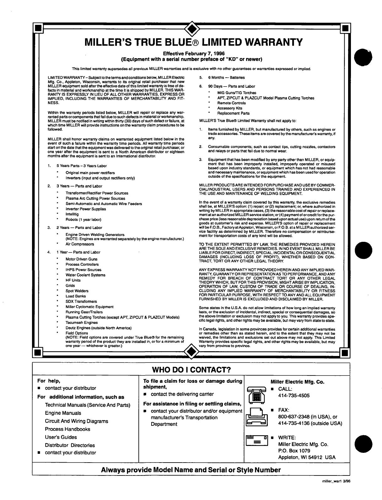
MILLERS
TRUE
BLUEfi
LIMITED
WARRANTY
Effective
February
7,
1996
(Equipment
with
a
serial
number
preface
of
KD
or
newer)
This
limited
warranty
supersedes
all
previous
MILLER
warranties
and
is
exclusive
with
no
other
guarantees
or
warranties
expressed
or
implied.
LIMITED
WARRANTY
Subject
to
theterms
and
conditions
below,
MILLER
Electric
1Mg.
Co.,
Appleton,
Wisconsin,
warrants
to
its
original
retail
purchaser
that
new
MILLER
equipment
sold
after
the
effective
date
of
this
limited
warranty
is
tree
of
de
tects
in
material
and
worfimanship
at
the
time
it
is
shipped
by
MILLER.
ThIS
WAR
RANTY
IS
EXPRESSLY
IN
LIEU
OF
ALL
OTHER
WARRANTIES,
EXPRESS
OR
IMPLIED,
INCLUDING
THE
WARRAN11ES
OF
MERCHANTABILITY
AND
FIT
NESS.
Within
the
warranty
periods
hated
below,
MILLER
will
mpair
or
replace
any
war
ranted
parts
orcomponenta
that
fail
due
to
such
defects
in
material
orworknranahip.
MILLER
must
be
notified
in
writing
within
thirty
(30)
days
of
auch
defect
or
failure,
at
which
lime
MILLER
will
provide
instructions
on
the
warranty
claim
procedures
to
be
followed.
MILLER
shall
honor
warranty
claims
on
warranted
equipment
listed
below
in
the
event
of
such
a
failure
within
the
warranty
time
periods.
All
warranty
time
periods
start
on
the
date
that
the
equipment
wax
delivered
to
the
original
retail
purchaser,
or
one
year
after
the
equipment
is
sent
to
a
North
American
distributor
or
eighteen
months
after
the
equipment
is
sent
to
an
Intemational
distributor.
t.
5YearxParts-3YearaLabor
Original
main
power
rectifiers
*
lnverterx
(input
and
output
rectifiers
only)
2.
3
Yeam
Parts
and
Labor
*
Tmnaformer/Rectifier
Power
Sources
*
Plasma
Arc
Cutting
Power
Sources
*
Semi-Automatic
and
Automatic
Wire
Feeders
*
Inverter
Power
Supplies
*
lntellitig
Robots
(t
year
labor)
3.
2
Yeam
Pans
and
Labor
Engine
Driven
Welding
Generators
(NOTE:
Engines
are
warranted
separately
by
the
engine
manufacturer.)
Air
Compmaaors
4.
t
YearPartaand
Labor
*
Motor
Driven
Guns
*
Process
Controllers
*
Il-PS
Power
Sources
Water
Coolant
Systems
HFUnita
*
Grids
*
Spot
Welders
*
Load
Banks
SDX
Tmnaformem
Miller
Cyclomatic
Equipment
*
Running
Gear/Trailem
*
Plasma
Cutting
Torches
(except
APT,
ZIPCUT
&
PLAZCUT
Models)
Tecumxeh
Engines
Deutz
Engines
(outside
North
America)
Field
Options
(NOTE:
Field
options
are
covered
under
True
Bluefi
for
the
remaining
warranty
period
of
the
product
they
are
installed
in,
or
for
a
minimum
of
one
year
whichever
is
greater.)
5.
6
Months
Batteries
e.
90
Days
Parts
and
Labor
*
MIG
Guns/fiG
Torches
APT,
ZIPCUT
&
PLAZCUT
Model
Plasma
Cutting
Torches
*
Remote
Controls
Accessory
Kita
*
Replacement
Parts
MILLERS
True
Bluefi
LImited
Warranty
ahall
not
apply
to:
t.
Items
fumiahed
by
MILLER,
but
manufactured
by
others,
such
as
engines
or
trade
accessories.
These
items
are
covered
by
the
manufacturera
warranty,
if
any.
2.
Consumable
components;
auch
as
contact
tipa,
cutting
nozzles,
contactora
and
relays
or
parts
that
fail
due
to
normal
wear.
3.
Equipment
that
has
been
modified
by
any
party
other
than
MILLER,
or
equip
ment
that
has
been
improperiy
installed,
impreperiy
operated
or
misused
based
upon
industry
standards,
or
equipment
which
has
not
had
reasonable
and
neceasary
maintenance,
or
equipment
which
has
been
used
for
operation
outside
of
the
apecificationa
for
the
equipment.
MILLER
PRODUCTSARE
INTENDED
FOR
PURCHASE
AND
USE
BY
COMMER
CIAL/INDUSTRIAL
USERS
AND
PERSONS
TRAINED
AND
EXPERIENCED
IN
ThE
USE
AND
MAINTENANCE
OF
WELDING
EQUIPMENT.
In
the
event
of
a
warranty
claim
covered
by
this
warranty,
the
exclusive
remediea
shall
be,
at
MILLERS
option:
(t)
repair;
or
(2)
replacement;
or,
where
authorized
in
writing
by
MILLER
in
appropriate
cases,
(3)
the
reasonable
coat
of
repairor
replace
ment
at
an
authorized
MILLER
service
station;
or
(4)
payment
of
orcredit
forthe
pur
chase
price
(less
reasonable
depreciation
based
upon
actual
use)
upon
retum
of
the
goods
at
customers
risk
and
expense.
MILLERS
option
of
repair
or
replacement
will
be
F.O.B.,
Factoryat
Appleton,
Wisconsin,
or
FOB.
at
a
MILLER
authorized
ser
vice
facility
as
determined
by
MILLER.
Therefore
no
compenastion
or
reimburse
ment
for
tmnaportation
costs
of
any
kind
will
be
allowed.
TO
ThE
EXTENT
PERMITTED
BY
LAW,
THE
REMEDIES
PROVIDED
HEREIN
ARE
ThE SOLE
AND
EXCLUSIVE
REMEDIES.
IN
NO
EVENTSHALL
MILLER
BE
LIABLE
FOR
DIRECT,
INDIRECT,
SPECIAL
INCIDENTAL
OR
CONSEQUENTIAL
DAMAGES
(INCLUDING
LOSS
OF
PROFIT),
WHETHER
BASED
ON
CON
TRACT,
TORT
OR
ANY
OTHER
LEGAL
ThEORY.
ANY
EXPRESS
WARRANTY
NOT
PROVIDED
HEREtN
AND
ANY
IMPLIED
WAR
RANTY,
GUARANTY
OR
REPRESENTATION
AS
TO
PERFORMANCE,
AND ANY
REMEDY
FOR
BREACH
OF
CONTRACT
TORT
OR
ANY
OThER
LEGAL
ThEORY
WHICH,
BUT
FOR
THIS
PROVISION,
MIGHTARISE
BY
IMPLICA11ON,
OPERATION
OF
LAW,
CUSTOM
OF
TRADE
OR
COURSE
OF
DEALING,
IN
CLUDING
ANY
IMPLIED
WARRANTY
OF
MERCHANTABILITY
OR
FITNESS
FOR
PARTICULAR
PURPOSE,
WITh
RESPECTTO
ANY
AND
ALL
EQUIPMENT
FURNISHED
BY
MILLER
IS
EXCLUDED
AND
DISCLAIMED BY
MILLER.
Some
states
in
the
U.S.A.
do
not
allow
limitations
of
how
long
an
implied
warranty
lasts,
or
the exclusion
of
incidental,
indirect,
special
or
consequential
damages,
so
the
above
limitation
or
exclusion
may
nut
apply
to
you.
This
warranty
provides
ape
cific
legal
rights,
and
other
rights
may
be
available,
but
may
vary
from
state
to
state.
In
Canada,
legislation
in
some
provinces
provides
for
certain
additional
warranties
or
remedies
other
than
as
stated
herein,
and
to
the
extent
that
they
may
nut
be
waived,
the
limitations
and
exclusions
aet
out
above
may
not
apply.
This
LImited
Warranty
provides
specific
legal
righta,
and
other
rights
may
be
available,
but
may
vary
from
province
to
province.
WHO
DO
I
CONTACT?
For
help,
contact
your
distributor
For
additional
information,
such
as
Technical
Manuals
(Service
And
Parts)
Engine
Manuals
Circuit
And
Wiring
Diagrams
ProcesS
Handbooks
To
file
a
claim
for
loss
or
damage
during
shipment,
a
contact
the
deliVering
carrier
For
assistance
in
filing
or
settling
claims,
contact
your
distributor
and/or
equipment
manufacturers
Transportation
Department
1rjjj~j
UJ~T]
Miller
Electric
Mfg.
Co.
CALL:
414-735-4505
U
FAX:
800-637-2348
On
USA),
or
414-735-4136
(outside
USA)
Users
Guides
Distributor
Directories
contact
your
distributor
1e
=
WRITE:
Miller
Electric
Mfg.
Co.
P.O.
BOX
1079
Appleton,
WI
54912
USA
Always
provide
Model
Name
and
Serial
or
Style
Number
.
I:
xw.,
r
I
miller_wart
3/96

Declaration
of
Conformity
for
European
Community
(CE)
Products
NOTE
L~
This
information
is
provided
for
units
with
CE
certification
(see
rating
label
on
unit).
Manufacturers
Name:
Manufacturers
Address:
conforms
to
the
following
Directives
and
Standards:
Directives
Low
Voltage
Directive:
73/23/EEC
Electromagnetic
Compatability
(EMC)
Directive:
89/336/EEC
Machinery
Directives:
89/392/EEC,
91/368/EEC,
93/C
133/04,
93/68/EEC
Standards
Arc
Welding
Equipment
Part
I:
Welding
Power
Sources:
lEG
974-1
(April
1995
Draft
Revision)
Arc
Welding
Equipment:
Wirefeed
Systems:
IEC
974-4
(May
1995
Draft
Revision)
Degrees
of
Protection
Provided
By
Enclosures
(IP
Code):
lEG
529:1989
Insulation
Coordination
For
Equipment
With
Low-Voltage
Systems:
Part
I:
Principles,
Requirments
and
Tests:
lEG
664-1:
1992
Electromagnetic
Gapatibility,
(EMC):
EN
50199
European
Contact:
Mr.
Luigi
Vacchini,
Managing
Director
MILLER
Europe
S.P.A.
Via
Privata
lseo
20098
San
Giuliano
Milanese,
Italy
Telephone:
39(02)98290-1
Fax:
39(02)98281-552
Declares
that
the
product:
Miller
Electric
Mfg.
Co.
1635
W.
Spencer
Street
Appleton,
WI
54914
USA
D-64
(product
name)
dec_con
1
7/95

.

SECTION
1
-
SAFETY
PRECAUTIONS
FOR
ARC
WELDING
OM-1
582L
6196
1-1.
Symbol
Usage
4A
Means
Warning!
Watch
Out!
There
are
possible
hazards
with
this
procedure!
The
possible
hazards
are
shown
in
the
adjoining
symbols.
A
ItT
Marks
a
special
safety
message.
Means
NOTE;
not
safety
related.
.
.1.
1-2.
Arc
Welding
Hazards
This
group
of
symbols
means
PARTS,
and
HOT
PARTS
hazar
Warning!
ds.
Consu
Watch
It
symb
Out!
ols
an
possible
d
related
ELECTRIC
instructions
SHOCK,
MOVING
below
for
necessary
actions
to
avoid
the
hazards.
a
WARNING
The
symbols
shown
below
are
used
throughout
this
manual
to
call
attention
to
and
identify
possible
hazards.
When
you
see
the
symbol,
watch
out,
and
follow
the
related
instructions
to
avoid
the
hazard.
The
safety
information
given
below
is
only
a
summary
of
the
more
complete
safety
information
found
in
the
Safety
Standards
listed
in
Section
1-4.
Read
and
follow
all
Safety
Standards.
Only
qualified
persons
should
install,
operate,
maintain,
and
repair
this
unit.
During
operation,
keep
everybody,
especially
children,
away.
ELECTRIC
SHOCK
can
kill.
Touching
live
electrical
parts
can
cause
fatal
shocks
or
severe
burns.
The
electrode
and
work
circuit
is
electrically
live
whenever
the
output
is
on.
The
input
power
circuit
and
machine
internal
circuits
are
also
live
when
power
is
on.
In
semiautomatic
or
automatic
wire
welding,
the
wire,
wire
reel,
drive
roll
housing,
and
all
metal
parts
touching
the
welding
wire
are
electrically
live.
Incorrectly
installed
or
improperly
grounded
equipment
is
a
hazard.
1.
Do
not
touch
live
electrical
parts.
2.
Wear
dry,
hole-free
insulating
gloves
and
body
protection.
3.
Insulate
yourself
from
work
and
ground
using
dry
insulating
mats
or
covers
big
enough
to
prevent
any
physical
contact
with
the
work
or
ground.
4.
Disconnect
input
power
or
stop
engine
before
installing
or
servicing
this
equipment.
Lockout/tagout
input
power
according
to
OSHA
29
CFR1910.147
(see
Safety
Standards).
5.
Properly
install
and
ground
this
equipment
according
to
its
Owners
Manual
and
national,
state,
and
local
codes.
6.
Always
verify
the
supply
ground
check
and
be
sure
that
input
oower
cord
around
wire
is
orooerlv
connected
to
around
terminal
in
disconnect
box
or
that
cord
plug
is
connected
to
a
properly
grounded
receptacle
outlet.
7.
When
making
input
connections,
attach
proper
grounding
conductor
first
double-check
connections.
8.
Frequently
inspect
input
power
cord
for
damage
or
bare
wiring
replace
cord
immediately
if
damaged
bare
wiring
can
kill.
9.
Turn
oft
all
equipment
when
not
in
use.
-
10.
Do
not
use
worn,
damaged,
undersized,
or
poorly
spliced
cables.
11.
Do
not
drape
cables
over
your
body.
12.
If
earth
grounding
of
the
workpiece
is
required,
ground
it
directly
with
a
separate
cable
do
not
use
work
clamp
or
work
cable.
13.
Do
not
touch
electrode
if
you
are
in
contact
with
the
work,
ground,
or
another
electrode
from
a
different
machine.
14.
Use
only
well-maintained
equipment.
Repair
or
replace
damaged
parts
at
once.
Maintain
unit
according
to
manual.
15.
Wear
a
safety
harness
if
working
above
floor
level.
16.
Keep
all
panels
and
covers
securely
in
place.
17.
Clamp
work
cable
with
good
metal-to-metal
contact
to
workoiece
or
worktable
as
near
the
weld
as
oractical.
safety_somi
4/95
ARC
RAYS
can
burn
eyes
and
skin;
ARC
RAYS
NOISE
can
damage
hearing;
FLYING
~
SLAG
OR
SPARKS
can
injure
eyes.
2.
Wear
a
welding
helmet
fitted
with
a
proper
shade
of
filter
to
protect
your
face
and
eyes
when
welding
or
watching
(see
ANSI
Arc
rays
from
the
welding
process
produce
intense
Z49.1
and
Z87.1
listed
in
Safety
Standards).
visible
and
invisible
(ultraviolet
and
infrared)
rays
that
can
bum
eyes
and
skin.
Noise
from
some
3.
Wear
approved
safety
glasses
with
side
shields.
processes
can
damage
hearing.
Chipping,
4.
Use
protective
screens
or
barriers
to
protect
others
from
flash
grinding,
and
welds
cooling
throw
off
pieces
of
metal
or
slag.
and
glare;
wam
others
not
to
watch
the
arc.
NOISE
5.
Wear
protective
clothing
made
from
durable,
flame-resistant
1.
Use
approved
ear
plugs
or
ear
muffs
if
noise
level
is
high.
material
(wool
and
leather)
and
foot
protection.
hazardous
to
your
health.
wearing
an
air-supplied
respirator.
Always
have
a
trained
r
FUMES
AND
GASES
can
~
5.
Work
in
a
confined
space
only
if
it
is
well
ventilated,
or
while
Welding
produces
fumes
and
gases.
Breathing
watchperson
nearby.
Welding
fumes
and
gases
can
displace
air
these
fumes
and
gases
can
be
hazardous
to
your
and
lower
the
oxygen
level
causing
injury
or
death.
Be
sure
the
health.
breathing
air
is
safe.
6.
Do
not
weld
in
locations
near
degreasing,
cleaning,
or
spraying
1.
Keep
your
head
out
of
the
fumes.
Do
not
breathe
the
fumes.
operations.
The
heat
and
rays
of
the
arc
can
react
with
vapors
to
2.
If
inside,
ventilate
the
area
and/or
use
exhaust
at
the
arc
to
form
highly
toxic
and
irritating
gases.
remove
welding
fumes
and
gases.
7.
Do
not
weld
on
coated
metais,
such
as
galvanized,
lead,
or
3.
If
ventilation
is
poor,
use
an
approved
air-supplied
respirator.
cadmium
plated
steel,
unless
the
coating
is
removed
from
the
4.
Read
the
Material
Safety
Data
Sheets
(MSDSs)
and
the
weld
area,
the
area
is
well
ventilated,
and
if
necessary,
while
manufacturers
instruction
for
metals,
consumables,
coatings,
wearing
an
air-supplied
respirator.
The
coatings
and
any
metals
cleaners,
and
degreasers.
containing
these
elements
can
give
off
toxic
fumes
if
welded.
OM-1582
Page
1
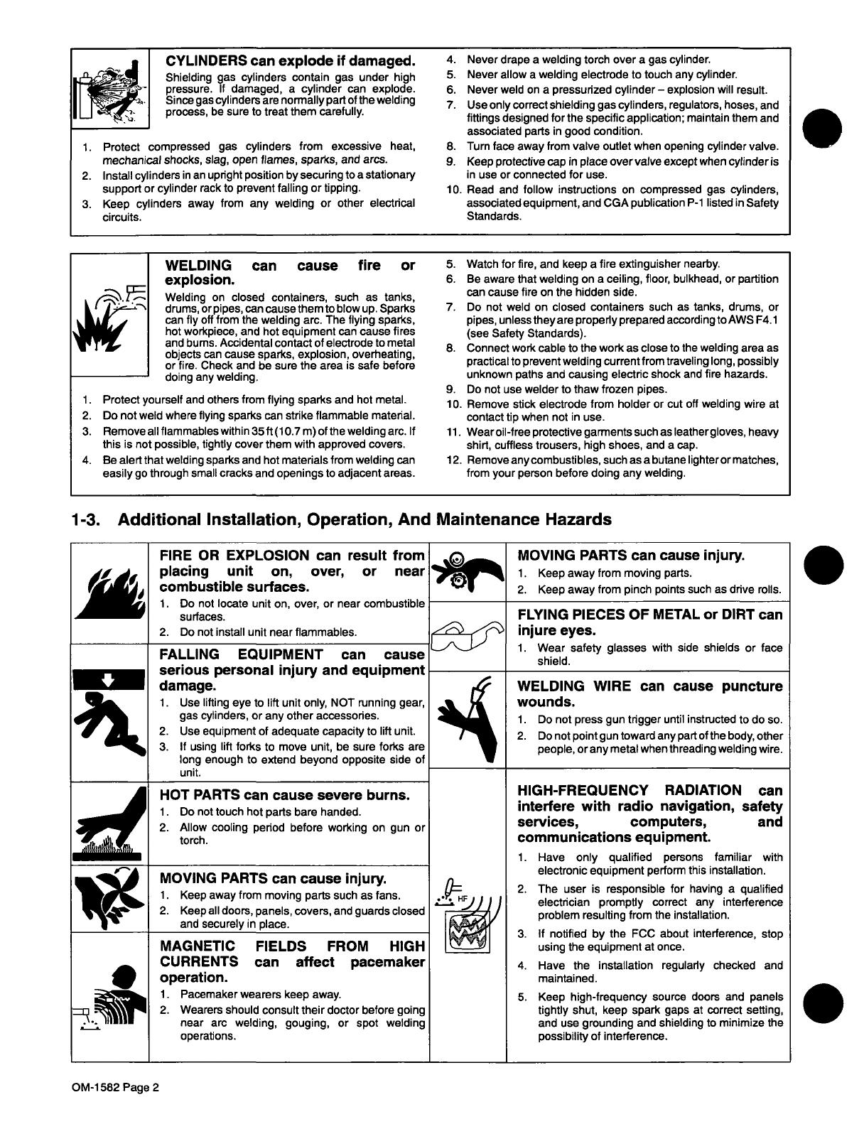
CYLINDERS
can
explode
if
damaged.
Shielding
gas
cylinders
contain
gas
under
high
pressure.
If
damaged,
a
cylinder
can
explode.
Since
gas
cylinders
are
normally
part
of
the
welding
process,
be
sure
to
treat
them
carefully.
1.
Protect
compressed
gas
cylinders
from
excessive
heat,
mechanical
shocks,
slag,
open
flames,
sparks,
and
arcs.
2.
Install
cylinders
in
an
upright
position
by
securing
to
a
stationary
support
or
cylinder
rack
to
prevent
falling
or
tipping.
3.
Keep
cylinders
away
from
any
welding
or
other
electrical
circuits.
4.
Never
drape
a
welding
torch
over
a
gas
cylinder.
5.
Never
allow
a
welding
electrode
to
touch
any
cylinder.
6.
Never
weld
on
a
pressurized
cylinder
explosion
will
result.
7.
Use
only
correct
shielding
gas
cylinders,
regulators,
hoses,
and
fittings
designed
for
the
specific
application;
maintain
them
and
associated
parts
in
good
condition.
8.
Turn
face
away
from
valve
outlet
when
opening
cylinder
valve.
9.
Keep
protective
cap
in
place
over
valve
except
when
cylinder
is
in
use
or
connected
for
use.
10.
Read
and
follow
instructions
on
compressed
gas
cylinders,
associated
equipment,
and
CGA
publication
P-i
listed
in
Safety
Standards.
WELDING
can
cause
fire
or
explosion.
Welding
on
closed
containers,
such
as
tanks,
drums,
or
pipes,
can
cause
them
to
blow
up.
Sparks
can
fly
off
from
the
welding
arc.
The
flying
sparks,
hot
workpiece,
and
hot
equipment
can
cause
fires
and
bums.
Accidental
contact
of
electrode
to
metal
objects
can
cause
sparks,
explosion,
overheating,
or
fire.
Check
and
be
sure
the
area
is
safe
before
doing
any
welding.
Protect
yourself
and
others
from
flying
sparks
and
hot
metal.
Do
not
weld
where
flying
sparks
can
strike
flammable
material.
Remove
all
flammables
within
35
ft
(10.7
m)
of
the
welding
arc.
If
this
is
not
possible,
tightly
cover
them
with
approved
covers.
4.
Be
alert
that
welding
sparks
and
hot
materials
from
welding
can
easily
go
through
small
cracks
and
openings
to
adjacent
areas.
5.
Watch
for
fire,
and
keep
a
fire
extinguisher
nearby.
6.
Be
aware
that
welding
on
a
ceiling,
floor,
bulkhead,
or
partition
can
cause
fire
on
the
hidden
side.
7.
Do
not
weld
on
closed
containers
such
as
tanks,
drums,
or
pipes,
unless
they
are
properly
prepared
according
to
AWS
F4.
1
(see
Safety
Standards).
8.
Connect
work
cable
to
the
work
as
close
to
the
welding
area
as
practical
to
prevent
welding
current
from
traveling
long,
possibly
unknown
paths
and
causing
electric
shock
and
fire
hazards.
9.
Do
not
use
welder
to
thaw
frozen
pipes.
10.
Remove
stick
electrode
from
holder
or
cut
oft
welding
wire
at
contact
tip
when
not
in
use.
11.
Wearoil-free
protective
garments
such
as
Ieathergloves,
heavy
shirt,
cuffless
trousers,
high
shoes,
and
a
cap.
12.
Remove
any
combustibles,
such
as
a
butane
lighteror
matches,
from
your
person
before
doing
any
welding.
1-3.
Additional
Installation,
Operation,
And
Maintenance
Hazards
Do
not
locate
unit
on,
over,
or
near
combustible
surfaces.
Do
not
install
unit
near
flammables.
FALLING
EQUIPMENT
can
cause
serious
personal
injury
and
equipment
damage.
1.
Use
lifting
eye
to
lift
unit
only,
NOT
running
gear,
gas
cylinders,
or
any
other
accessories.
Use
equipment
of
adequate
capacity
to
lift
unit.
If
using
lift
forks
to
move
unit,
be
sure
forks
are
long
enough
to
extend
beyond
opposite
side
of
unit.
HOT
PARTS
can
cause
severe
burns.
Do
not
touch
hot
parts
bare
handed.
Allow
cooling
period
before
working
on
gun
or
torch.
MOVING
PARTS
can
cause
injury.
Keep
away
from
moving
parts
such
as
fans.
Keep
all
doors,
panels,
covers,
and
guards
closed
and
securely
in
place.
MAGNETIC
FIELDS
FROM
HIGH
CURRENTS
can
affect
pacemaker
operation.
1.
Pacemaker
wearers
keep
away.
Wearers
should
consult
their
doctor
before
going
near
arc
welding,
gouging,
or
spot
welding
operations.
MOVING
PARTS
can
cause
injury.
1.
Keep
away
from
moving
parts.
2.
Keep
away
from
pinch
points
such
as
drive
rolls.
FLYING
PIECES
OF
METAL
or
DIRT
can
injure
eyes.
1.
Wear
safety
glasses
with
side
shields
or
face
shield.
WELDING
WIRE
can
cause
puncture
wounds.
2.
Do
not
point
gun
toward
any
part
of
the
body,
other
people,
or
any
metal
when
threading
welding
wire.
HIGH-FREQUENCY
RADIATION
interfere
with
radio
navigation,
services,
computers,
communications
equipment.
Have
only
qualified
persons
familiar
with
electronic
equipment
perform
this
installation.
The
user
is
responsible
for
having
a
qualified
electrician
promptly
correct
any
interference
problem
resulting
from
the
installation.
If
notified
by
the
FCC
about
interference,
stop
using
the
equipment
at
once.
Have
the
installation
regularly
checked
and
maintained.
Keep
high-frequency
source
doors
and
panels
tightly
shut,
keep
spark
gaps
at
correct
setting,
and
use
grounding
and
shielding
to
minimize
the
possibility
of
interference.
1.
2.
3.
FIRE
OR
EXPLOSION
can
result
from
placing
unit
on,
over,
or
near
combustible
surfaces.
~I1~
1.
Do
not
press
gun
trigger
until
instructed
to
do
so.
can
safety
and
.
OM-i
582
Page
2

I
I
OVERUSE
can
cause
OVERHEATED
EQUIPMENT.
1.
Allow
cooling
period.
2.
Reduce
current
or
reduce
duty
cycle
before
starting
to
weld
again,
3.
Follow
rated
duty
cycle,
~
SIGNIFICANT
DC
VOLTAGE
exists
after
removal
of
input
power
on
inverters.
1.
Turn
Off
inverter,
disconnect
input
power,
and
discharge
input
capacitors
according
to
instructions
in
Maintenance
Section
before
touching
any
parts.
on
circuit
boards.
1.
Put
on
grounded
wrist
strap
BEFORE
handling
STATIC
ELECTRICITY
can
damage
parts
boards
or
parts.
2.
Use
proper
static-proof
bags
and
boxes
to
store,
move,
or
ship
PC
boards.
-
BUILDUP
OF
SHIELDING
GAS
can
harm
health
or
kill.
1.
Shut
off
shielding
gas
supply
when
not
in
use.
1-4.
Principal
Safety
Standards
Safety
in
Welding
and
Cutting,
ANSI
Standard
Z49.
1
from
Safe
Handling
of
Compressed
Gases
in
Cylinders,
CGA
Pamphlet
American
Welding
Society,
550
N.W.
LeJeune
Rd,
Miami
FL
33126
P-i,
from
Compressed
Gas
Association,
1235
Jefferson
Davis
Highway,
Suite
501,
Arlington,
VA
22202.
Safety
and
Health
Standards,
OSHA
29
CFR
1910,
from
Superintendent
of
Documents,
U.S.
Government
Printing
Office,
Code
for
Safety
in
Welding
and
Cutting,
CSA
Standard
W117.2,
Washington,
D.C.
20402.
from
Canadian
Standards
Association,
Standards
Sales,
178
Rexdale
Boulevard,
Rexdale,
Ontario,
Canada
M9W
1
R3.
Recommended
Safe
Practices
for
the
Preparation
for
Welding
and
Safe
Practices
For
Occupation
And
Educational
Eye
And
Face
Cutting
of
Containers
That
Have
Held
Hazardous
Substances,
Protection,
ANSI
Standard
Z87.1,
from
American
National
American
Welding
Society
Standard
AWS
F4.1,
from
American
Standards
Institute,
1430
Broadway,
New
York,
NY
10018.
Welding
Society,
550
N.W.
LeJeune
Rd,
Miami,
FL
33126
Cutting
And
Welding
Processes,
NFPA
Standard
SiB,
from
National
Electrical
Code,
NFPA
Standard
70,
from
National
Fire
National
Fire
Protection
Association,
Batterymarch
Park,
Quincy,
Protection
Association,
Batterymarch
Park,
Quincy,
MA
02269.
MA
02269.
1-5.
EMF
Information
Considerations
About
Welding
And The
Effects
Of
Low
Frequency
To
reduce
magnetic
fields
in
the
workplace,
use
the
following
Electric
And
Magnetic
Fields
procedures:
The
following
is
a
quotation
from
the
General
Conclusions
Section
1.
Keep
cables
close
together
by
twisting
or
taping
them.
of
the
U.S.
Congress,
Office
of
Technology
Assessment,
Biological
Effects
of
Power
Frequency
Electric
&
Magnetic
Fields
2.
Arrange
cables
to
one
side
and
away
from
the
operator.
Background
Paper,
OTA-BP-E-53
(Washington,
DC:
U.S.
Government
Printing
Office,
May
1989):
there
is
now
a
very
3.
Do
not
coil
or
drape
cables
around
the
body.
large
volume
of
scientific
findings
based
on
experiments
at
the
cellular
level
and
from
studies
with
animals
and
people
which
clearly
4.
Keep
welding
power
source
and
cables
as
far
away
as
establish
that
low
frequency
magnetic
fields
can
interact
with,
and
practical.
produce
changes
in,
biological
systems.
While
most
of
this
work
is
of
very
high
quality,
the
results
are
complex.
Current
scientific
5.
Connect
work
clamp
to
workpiece
as
close
to
the
weld
as
understanding
does
not
yet
allow
us
to
interpret
the
evidence
in
a
possible.
single
coherent
framework.
Even
more
frustrating,
it
does
not
yet
About
Pacemakers:
allow
us
to
draw
definite
conclusions
about
questions
of
possible
riskortoofferclearscience-basedadviceonstrategiestorninimize
The
above
procedures
are
also
recommended
for
pacemaker
or
avoid
potential
risks.
wearers.
Consult
your
doctor
for
complete
information.
OM-1
582
Page
3
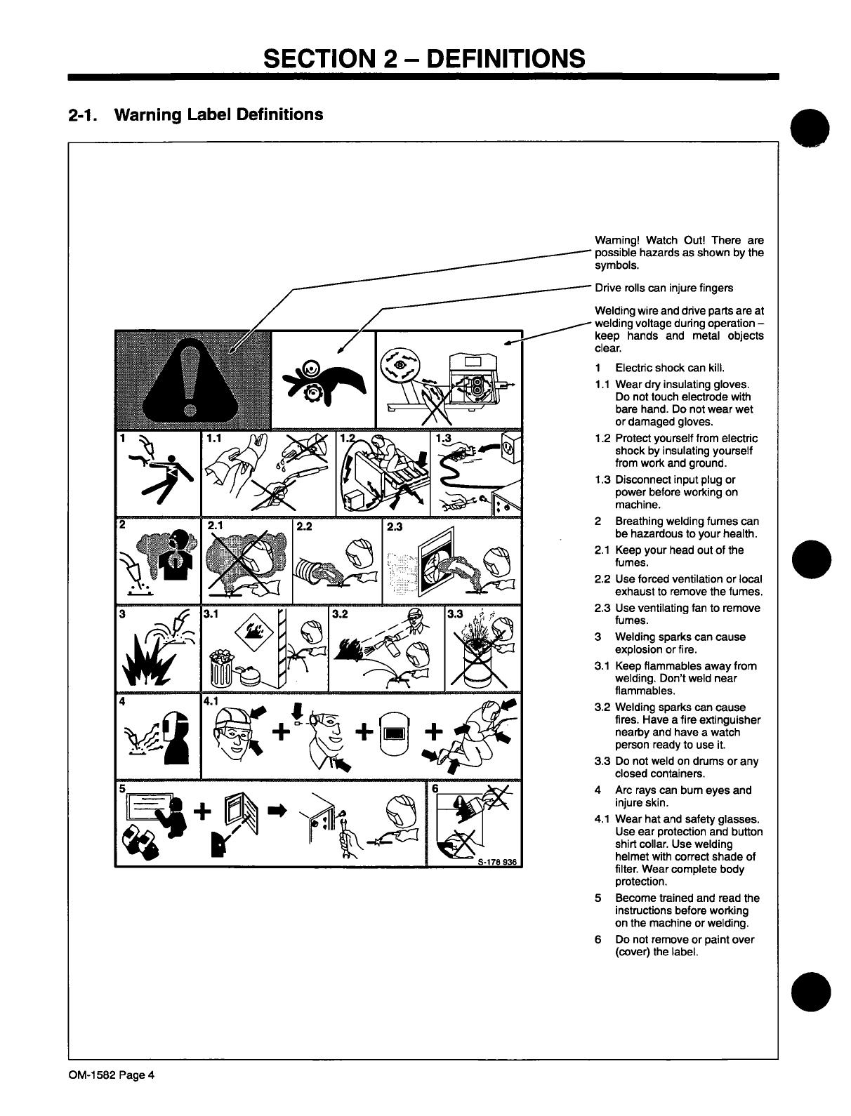
SECTION
2-
DEFINITIONS
2-1.
Warning
Label
Definitions
Warning!
Watch
Out!
There
are
possible
hazards
as
shown
by
the
symbols.
Drive
rolls
can
injure
fingers
Welding
wire
and
drive
parts
are
at
welding
voltage
during
operation
keep
hands
and
metal
objects
clear.
1
Electric
shock
can
kill.
1.1
Wear
dry
insulating
gloves.
Do
not
touch
electrode
with
bare
hand.
Do
not
wear
wet
or
damaged
gloves.
1.2
Protect
yourself
from
electric
shock
by
insulating
yourself
from
work
and
ground.
1.3
Disconnect
input
plug
or
power
before
working
on
machine.
2
Breathing
welding
fumes
can
be
hazardous
to
your
health.
2.1
Keep
your
head
out
of
the
fumes.
2.2
Use
forced
ventilation
or
local
exhaust
to
remove
the
fumes.
2.3
Use
ventilating
fan
to
remove
fumes.
3
Welding
sparks
can
cause
explosion
or
fire.
3.1
Keep
flammables
away
from
welding.
Dont
weld
near
flammables.
3.2
Welding
sparks
can
cause
fires.
Have
a
fire
extinguisher
nearby
and
have
a
watch
person
ready
to
use
it.
3.3
Do
not
weld
on
drums
or
any
closed
containers.
4
Arc
rays
can
bum
eyes
and
injure
skin.
4.1
Wear
hat
and
safety
glasses.
Use
ear
protection
and
button
shirt
collar.
Use
welding
helmet
with
correct
shade
of
filter.
Wear
complete
body
protection.
5
Become
trained
and
read
the
instructions
before
working
on
the
machine
or
welding.
6
Do
not
remove
or
paint
over
(cover)
the
label.
OM-1582
Page
4
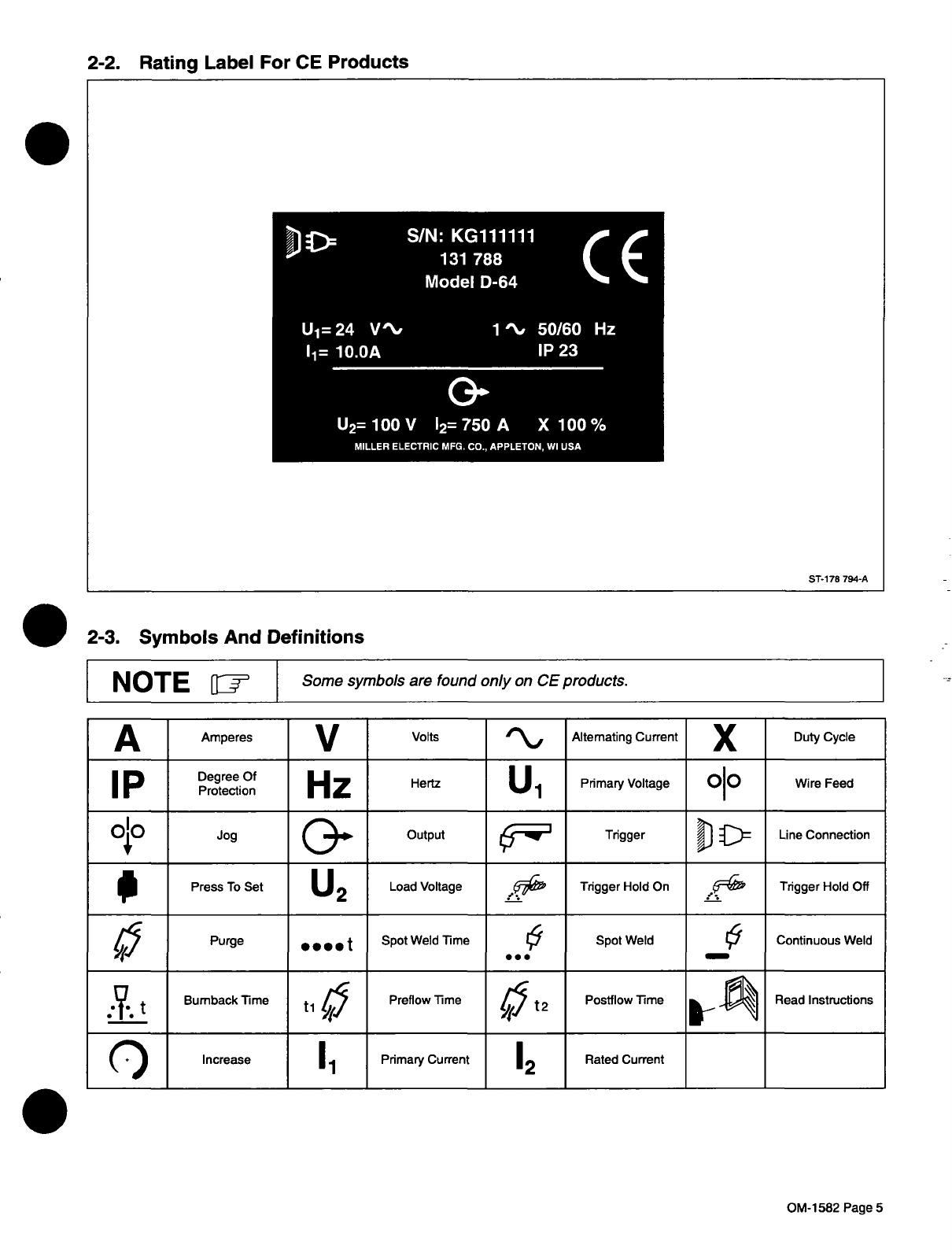
2-2.
Rating
Label
For
CE
Products
2-3.
Symbols
And
Definitions
NOTE
~
Some
symbols
are
found
only
on
CE
products.
A
Amperes
V
Volts
4t~%~,
Alternating
Current
Duty
Cycle
I
P
Hz
Hertz
~.1
Pnmary
Voltage
010
Wire
Feed
010
Jog
(~~up-
Output
Trigger
~J
~
Line
Connection
0
Press
To
Set
U2
Load
Voltage
Trigger
Hold
On
Trigger
Hold
Off
Purge
....
t
Spot
Weld
Time
Spot
Weld
t9
Continuous
Weld
~
t
Bumback
Time
ti
Preflow
Time
t2
Postflow
Time
Read
Instructions
(:)
Increase
Primary
Current
12
Rated
Current
S/N:KG111111
CE
Model
D-64
U1=24
V\~
1\~
50/60
Hz
11=10.OA
1P23
0~
U2=
100
V
12=
750
A
X
100
%
MILLER
ELECTRIC
MFG.
CO.,
APPLETON,
WI
USA
ST-i
78
794-A
OM-l
582
Page
5

3-1.
Site
Selection
SECTION
3-
INSTALLATION
3-2.
Gun
Recommendation
Table
Process
I
Gun
I
GMAW
Hard
or
Cored
Wires
M25, M40,
GA-50C,
GW-500,
Or
GW-600
FCAW
Self-Shielding
Wires
GA-4OGL
Or
GA-5OGL
OM-1582
Page
6
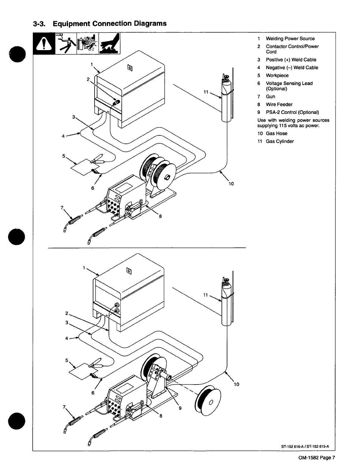
3-3.
Equipment
Connection
Diagrams
Welding
Power
Source
Contactor
Control/Power
Cord
Positive
(+)
Weld
Cable
Negative
()
Weld
Cable
Workpiece
Voltage
Sensing
Lead
(Optional)
8
Wire
Feeder
9
PSA-2
Control
(Optional)
Use
with
welding
power
sources
supplying
115
volts
ac
power.
10
Gas
Hose
11
Gas
Cylinder
7~
OM-1582
Page
7

3-4.
Rear
Panel
Connections
~jI.~*
Pin
Information
A
24
volts
ac
with
respect
to
socket
G.
B
Contact
closure
to
A
completes
24
volts
ac
contactor
control
circuit.
G
Circuit
common
for
24
volts
AC
circuit.
C
+10
volts
dc
output
to
remote
control
with
respect
to
socket
D.
D
Remote
control
circuit
common.
E
0
to
+10
volts
dc
input
command
signal
from
remote
control
with
respect
to
socket
D.
H
Voltage
feedback;
0
to
+10
volts
dc,
1
volt
per
10
arc
volts.
F
Current
feedback;
0
to
+10
volts
dc,
1
volt
per
100
amperes.
*The
remaining
pins
are
not
used.
3-5.
14-Pin
Plug
Information
OM-1582
Page
8
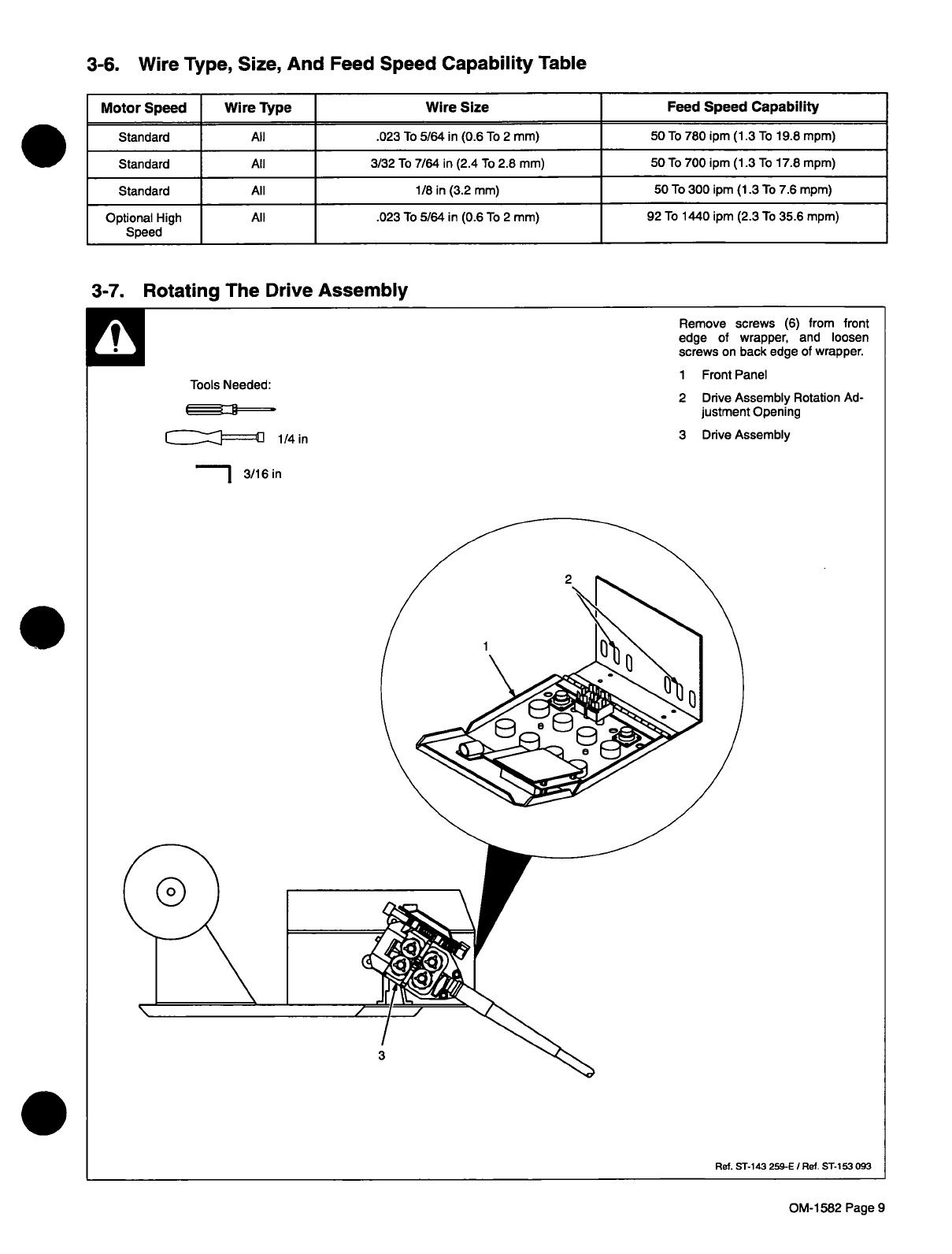
3-6.
Wire
Type,
Size,
And
Feed
Speed
Capability
Table
Motor
Speed
Wire
Type
Wire
Size
Feed
Speed
Capability
Standard
All
.023
To
5/64
in
(0.6
To
2
mm)
50
To
780
1pm
(1.3
To
19.8
mpm)
Standard
All
3/32
To
7/64
in
(2.4
To
2.8
mm)
50
To
700
1pm
(1.3
To
17.8
mpm)
Standard
All
1/8
in
(3.2
mm)
50
To
300
ipm
(1.3
To
7.6
mpm)
Optional
High
Speed
All
.023
To
5/64
in
(0.6
To
2
mm)
92
To
1440
ipm
(2.3
To
35.6
mpm)
3-7.
Rotating
The
Drive
Assembly
OM-1
582
Page
9
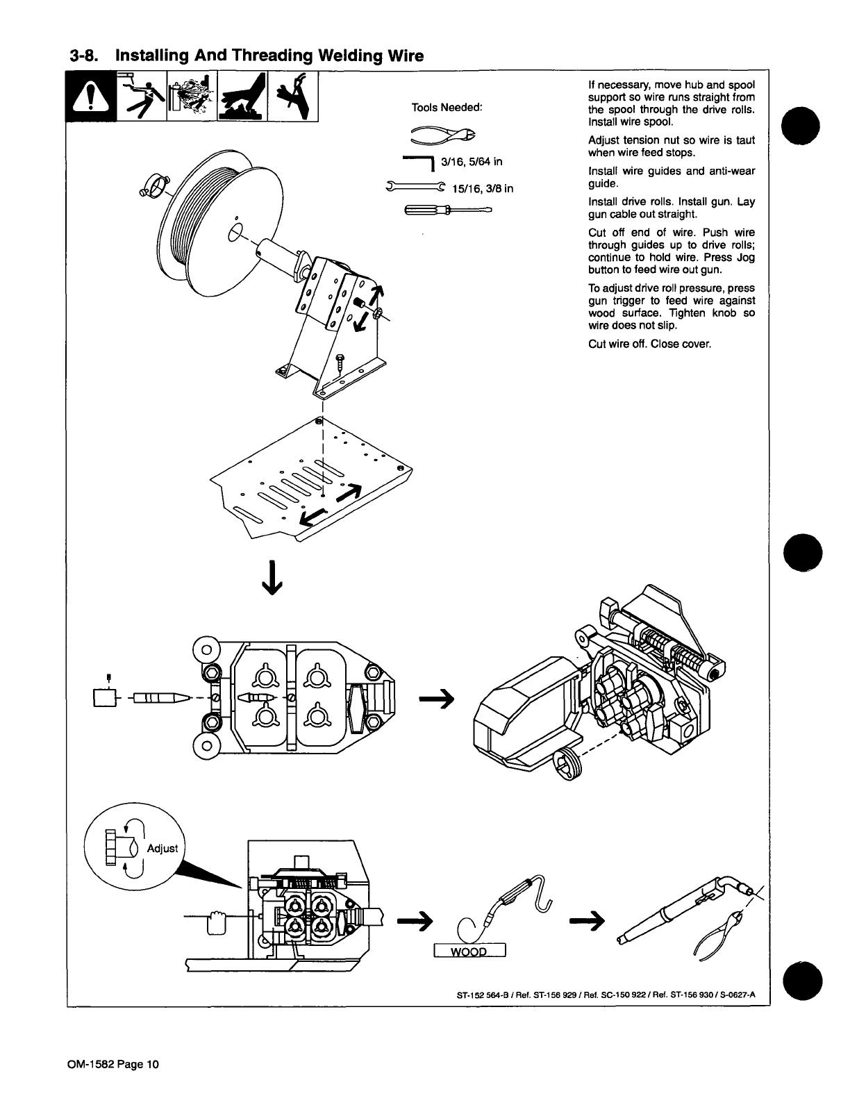
3-8.
Installing
And
Threading
Welding
Wire
If
necessary,
move
hub
and
spool
support
so
wire
runs
straight
from
the
spool
through
the
drive
rolls.
Install
wire
spool.
Adjust
tension
nut
so
wire
is
taut
when
wire
feed
stops.
Install
wire
guides
and
anti-wear
guide.
Install
drive
rolls.
Install
gun.
Lay
gun
cable
out
straight.
Cut
off
end
of
wire.
Push
wire
through
guides
up
to
drive
rolls;
continue
to
hold
wire.
Press
Jog
button
to
feed
wire
out
gun.
To
adjust
drive
roll
pressure,
press
gun
trigger
to
feed
wire
against
wood
surface.
Tighten
knob
so
wire
does
not
slip.
Cut
wire
oft.
Close
cover.
-*
ST-i
52564-B
/
Ref.
ST-i
56
929
I
Ref.
SC-i
50
922/Ref.
ST-i
56
930
/
S-0627-A
Tools
Needed:
3/16,5/64
in
15/16,3/8
in
.
4,
Eoii~-1z~
lk~
O~
\\_~1
cA0
OM-1
582
Page
10
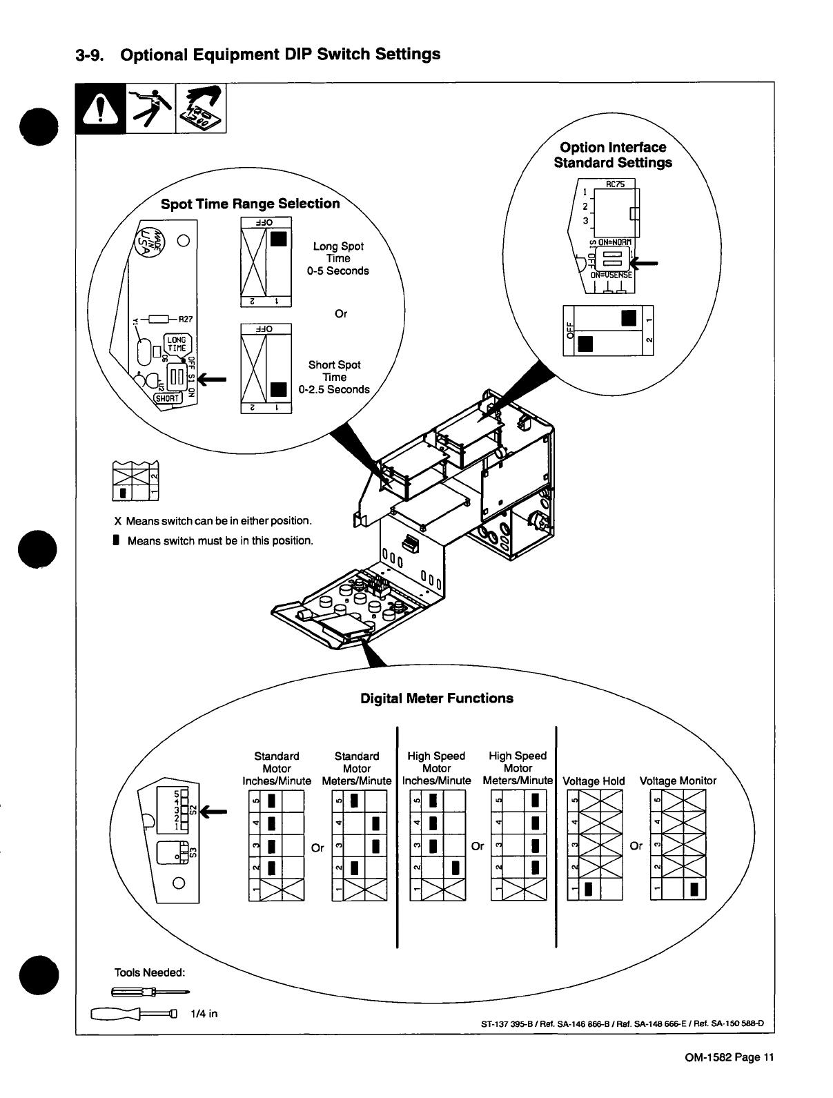
3-9.
Optional
Equipment
DIP
Switch
Settings
X
Means
switch
can
be
in
either
position.
I
Means
switch
must
be
in
this
position.
Digital
Meter
Functions
Option
Interface
Standard
Settings
0-5
Seconds
ddO
.
Or
..-
ci.
Standard
Motor
Inches/Minute
Standard
Motor
Meters/Minute
U
~
I
~
I
C.
~
~
Or
High
Speed
Motor
Inches/Minute
0~
~
High
Speed
Motor
Meters/Minute
I
U
CU
Or
Voltage
Hold
I~
Lk~
Lk~fl~
rr~
LL~
L~i
Tools
Needed:
c~~I====zn
1/4
in
ST-137
395-BI
Ref.
SA-146
866-B
/
Ref.
SA-148
666-E
/
Ref.
SA-150
588-0
OM-1582
Page
11

3-10.
Changing
Optional
Digital
Voltage
Control
For
Use
With
A
MILLER
Inverter-Type
Power
Source
1
Digital
Voltage
Control
Board
Connections
For
Standard
Use
2
Digital
Voltage
Control
Board
Connections
For
Use
With
In
verter-Type
Welding
Power
Source
Change
plug
connections
as
shown.
3
Calibration
Potentiometer
R31
___________
/1
~LI
LII
3
E
Tools
Needed:
Calibrate
Volts
meter
as
follows:
Rotate
Schedule
A
or
Schedule
B
Voltage
Control,
whichever
is
ac
tive,
to
the
maximum
position.
Turn
On
wire
feeder
and
welding
power
source.
Adjust
R31
until
wire
feeder
Volts
meter
displays
a
voltage
equal
to
the
maximum
voltage
listed
on
the
Voltage/Amperage
control
of
the
welding
power
source
nameplate.
Make
a
sample
weld
(at
desired
preset
voltage)
to
see
if
actual
arc
voltage
displayed
by
the
wire
feed
er
Volts
meter
is
different
than
pre
set
arc
voltage
due
to
cable
resis
tance,
poor
connections,
etc.
If
there
is
a
difference,
R31
can
be
adjusted
until
preset
voltage
is
closer
to
actual
arc
voltage.
Close
and
secure
front
panel,
and
reinstall
wrapper.
.
If
wire
feeder
is
being
used
with
a
MILLER
inverter-type
power
source
that
has
a
volt
age
range
of
10
to
35
volts
in
the
CV
mode,
no
calibration
is
required.
cIII:::::J====in
1/4
in
.
ST-137
395-B
I
S-0891
OM-1
582
Page
12

4-1.
Front
Panel
Controls
3
4
5
6
7
8
9
10
SECTION
4-
OPERATION
ST-152
647
1
Voltmeter
(Optional)
(See
Section
3-9)
2
Wire
Speed
Meter
(Optional)
Factory
set
to
display
inches
per
minute.
If
display
of
meters
per
minute
is
desired,
see
Section
4-2.
3
Schedule
A
Wire
Speed
Control
The
scale
is
calibrated
in
inches
per
minute
x
100
and
meter
per
minute.
4
Schedule
A
Voltage
Control
(Optional)
When
a
digital
voltage
control
is
used
with
a
MILLER
inverter-type
welding
power
source,
the
control
functions
as
a
remote
digital
voltage
control
to
preset
arc
voltage.
l~
For
dual
schedule
applications,
a
dual
schedule
switch
is
required
for
the
gun.
Obtain
a
proper
dual
schedule
switch
and
install
according
to
its
instructions.
5
Schedule
B
Indicator
Light
(Optional)
6
Schedule
B
Wire
Speed
Control
(Optional)
7
Schedule
B
Voltage
Control
(Optional)
8
Press
To
Set
Button
(Optional)
Press
and
hold
button
to
preset
Schedule
B
wire
feed
speed
and/or
voltage.
9
Left
And
Right
Indicator
Lights
10
Jog/Purge
Switch
Pushup
to
momentarily
feed
welding
wire
at
speed
set
on
Wire
Speed
control
without
energizing
welding
circuit
or
shielding
gas
valve.
Push
down
to
momentarily
energize
gas
valve
to
purge
air
from
gun
or
adjust
gas
regulator.
Center
position
is
off.
OM-1
582
Page
13
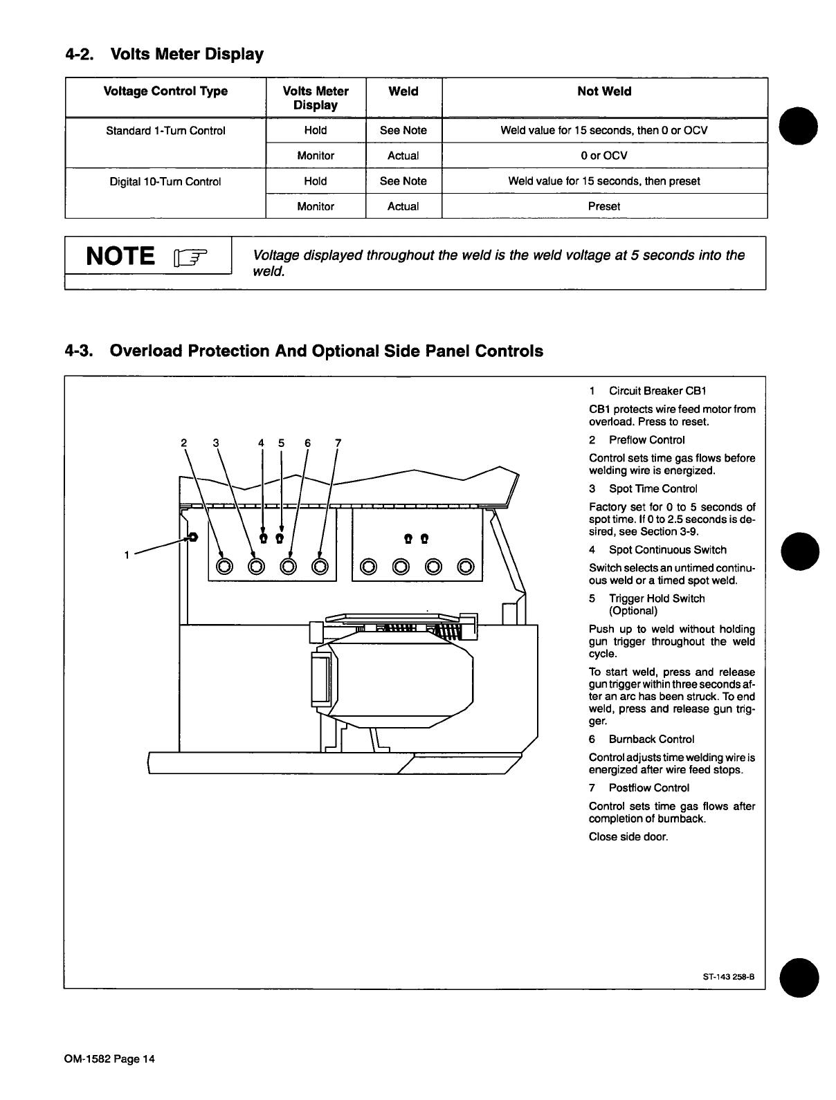
4-2.
Volts
Meter
Display
1
Circuit
Breaker
CB1
CB1
protects
wire
feed
motor
from
overload.
Press
to
reset.
2
Preflow
Control
Control
sets
time
gas
flows
before
welding
wire
is
energized.
3
Spot
Time
Control
Factory
set
for
0
to
5
seconds
of
spot
time.
ItO
to
2.5
seconds
is
de
sired,
see
Section
3-9.
4
Spot
Continuous
Switch
Switch
selects
an
untimed
continu
ous
weld
or
a
timed
spot
weld.
5
Trigger
Hold
Switch
(Optional)
Push
up
to
weld
without
holding
gun
trigger
throughout
the
weld
cycle.
To
start
weld,
press
and
release
gun
trigger
within
three
seconds
af
ter
an
arc
has
been
struck.
To
end
weld,
press
and
release
gun
trig-
ger.
6
Burnback
Control
Control
adjusts
time
welding
wire
is
energized
after
wire
feed
stops.
7
Postflow
Control
Control
sets
time
gas
flows
after
completion
of
bumback.
Close
side
door.
.
Voltage
Control
Type
Volts
Meter
Display
Weld
Not
Weld
Standard
1-Turn
Control
Hold
See
Note
Weld
value
for
15
seconds,
then
0
or
CCV
Monitor
Actual
0
or
CCV
Digital
10-Turn
Control
Hold
See
Note
Weld
value
for
15
seconds,
then
preset
Monitor
Actual
Preset
NOTE
~
Voltage
displayed
throughout
the
weld
is
the
weld
voltage
at
5
seconds
into
the
weld.
4-3.
Overload
Protection
And
Optional
Side
Panel
Controls
ST-143
258-B
OM-1582
Page
14
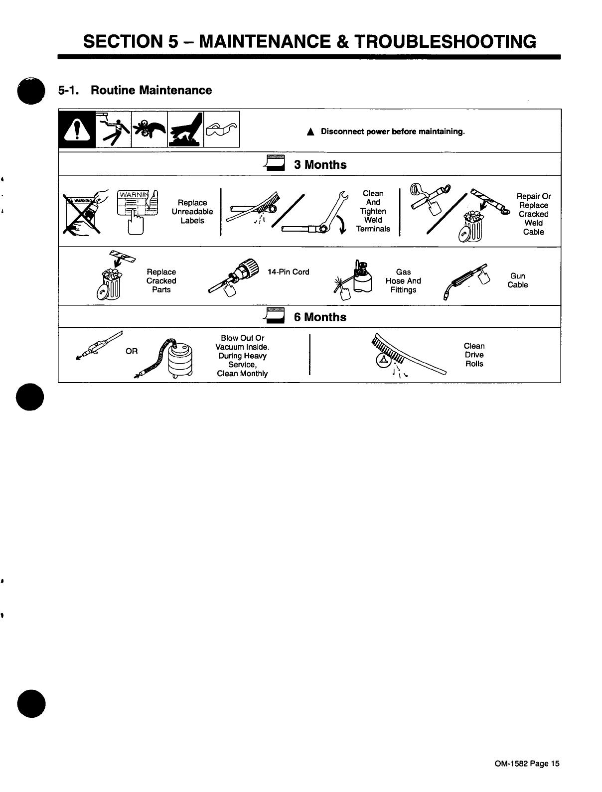
SECTION
5-
MAINTENANCE
&
TROUBLESHOOTING
5-1.
Routine
Maintenance
OM-1
582
Page
15

5-2.
Troubleshooting
A
Disconnect
power
before
troubleshooting
Trouble
Remedy
Wire
feeds,
shielding
gas
flows,
but
electrode
wire
is
not
energized.
Check
interconnecting
cord
connections,
If
secure,
check
cord
for
continuity
and
repair
or
replace
(see
Sections
3-3
and
3-4).
Wire
feeder
is
on,
meter(s)
do
not
light
up,
motor
does
not
run,
gas
valve
and
welding
power
source
contactor
do
not
pull
in.
Check
and
reset
CB1
(see
Section
4-3).
Electrode
wire
feeding
stops
or
feeds
erratically
during
welding.
Check
gun
trigger
connection.
See
gun
Owners
Manual.
Check
gun
trigger.
See
gun
Owners
Manual.
Readjust
hub
tension
and
drive
roll
pressure
(see
Section
3-8).
Change
to
correct
size
drive
roll
(see
Table
7-1).
Clean
or
replace
dirty
or
worn
drive
roll.
Incorrect
size
or
worn
wire
guides.
Replace
contact
tip
or
liner.
See
gun
Owners
Manual.
Remove
weld
spatter
or
foreign
matter
from
around
nozzle
opening.
Have
Factory
Authorized
Service
Agency
check
drive
motor
or
motor
control
board
PCi.
Motor
runs
slowly.
Check
for
correct
input
voltage.
Wire
does
not
feed
until
trigger
is
pulled,
but
continues
to
feed
after
trigger
is
re-
leased,
and
trigger
hold
is
not
on.
Check
for
a
short
between
welding
gun
trigger
leads
and
weld
cable.
Repair
short
or
replace
welding
gun.
Gas
valve
in
feeder
is
rattling
loudly
along
with
possible
erratic
or
slow
wire
feed
speed.
Check
for
a
short
between
welding
gun
trigger
leads
and
weld
cable.
Repair
short
or
replace
welding
gun.
Unit
does
not
switch
out
of
Run-In
Speed.
Install,
reconnect,
or
replace
voltage
sensing
lead
(see
Section
3-3).
Wire
feeder
power
is
on,
displays
light
up,
but
unit
is
inoperative.
Check
welding
gun
trigger
leads
for
continuity,
and
repair
leads
or
replace
gun.
Schedule
A
Wire
Feed
Speed
works,
but
Schedule
B
Wire
Feed
Speed
does
not
work
or
is
erratic.
DIP
Switch
S1(1)
on
Option
Interface
Board
PC7O
must
be
in
the
On
position
(see
Section
3-9).
Wire
Feed
Speed
Meter
display
does
not
match
actual
wire
feed
speed.
Set
DIP
Switch
S2
on
Meter
Board
PC6O
in
Inches/Minute
mode
(see
Section
3-9).
Actual
arc
voltage
display
on
meter
is
held
after
trigger
is
released,
or
arc
volt
age
does
not
change
while
welding.
Set
DIP
Switch
S2
on
Meter
Board
PC6O
in
Voltage
Monitor
mode
(see
Section
3-9).
.
OM-1582
Page
16
/