TECHNICAL & SERVICE MANUAL
CONTENTS
1. PART NAMES AND FUNCTIONS ········2
2. SPECIFICATIONS·································4
3. OUTLINES AND DIMENSIONS··········14
4. WIRING DIAGRAM ·····························15
5.
REFRIGERANT SYSTEM DIAGRAM
·······16
6. HEATER CONTROL ···························17
7. TROUBLESHOOTING·························20
8. DISASSEMBLY PROCEDURE ···········30
INDOOR UNIT
Indoor unit
[Model names] [Service Ref.]
SEZ-KD09NA SEZ-KD09NA.TH
SEZ-KD12NA SEZ-KD12NA.TH
SEZ-KD15NA SEZ-KD15NA.TH
SEZ-KD18NA SEZ-KD18NA.TH
SPLIT-TYPE, HEAT PUMP AIR CONDITIONERS
WIRED REMOTE
CONTROLLER
ON/OFF
TEMP.
Model name
indication
No.HWE08020
REVISED EDITION-B
November 2008
CM
I
N
T
E
R
T
E
K
L
I
S
T
E
D

2
1PART NAMES AND FUNCTIONS
Indoor Unit
SEZ-KD09NA.TH
SEZ-KD12NA.TH
SEZ-KD15NA.TH
SEZ-KD18NA.TH
Air outlet duct flange
Air outlet
Air inlet
● Operation buttons
Once the controls are set, the same operation mode can be repeated by simply pressing the ON/OFF button.
Wired remote controller
PAR-21MAA
ON/OFF
FILTER
CHECK
OPERATION
CLEAR
TEST
TEMP.
MENU
BACK DAY
MONITOR/SET
CLOCK
ON/OFF
Set Temperature buttons
Down
Up
Timer Menu button
(Monitor/Set button)
Mode button (Return button)
Set Time buttons
Back
Ahead
Timer On/Off button
(Set Day button)
Opening the
door
Start/Stop button
Fan Speed button
Filter button
(<return sign> button)
Test Run button
Service button (Clear button)
Airflow Up/Down button
Louver button
( Operation button)
To preceding operation
number
Ventilation button
( Operation button)
To next operation number

3
●Display
For purposes of this explanation,
all parts of the display are shown
as lit. During actual operation, only
the relevant items will be lit.
˚F˚C
˚F˚C
ERROR CODE
AFTER
TIMER
TIME SUN MON TUE WED THU FRI SAT
ON
OFF
Hr
AFTER
FILTER
FUNCTION
ONLY1Hr.
WEEKLY
SIMPLE
AUTO OFF
Identifies the current operation
Shows the operating mode, etc.
* Multilanguage display is sup-
ported.
“Centrally Controlled” indicator
Indicates that operation of the re-
mote controller has been prohib-
ited by a master controller.
“Timer Is Off” indicator
Indicates that the timer is off.
Temperature Setting
Shows the target temperature.
Day-of-Week
Shows the current day of the week.
Time/Timer Display
Shows the current time (The 12 hour clock or The 24
hour clock), unless the simple or Auto Off timer is set.
If the simple or Auto Off timer is set, shows the time
remaining.
“Sensor” indication
Displayed when the remote controller
sensor is used.
“Locked” indicator
Indicates that remote controller but-
tons have been locked.
“Clean The Filter” indicator
Comes on when it is time to clean the
filter.
Timer indicators
The indicator comes on if the corre-
sponding timer is set.
Up/Down Air Direction indica-
tor
The indicator shows the direc-
tion of the outcoming airflow.
“One Hour Only” indicator
Displayed if the airflow is set to
Low and downward during COOL
or DRY mode. (Operation varies
according to model.)
The indicator goes off after one
hour, at which time the airflow di-
rection also changes.
Room Temperature display
Shows the room temperature.
Louver display
Indicates the action of the swing
louver. Does not appear if the
louver is stationary.
(Power On indicator)
Indicates that the power is on.
Fan Speed indicator
Shows the selected fan speed.
Ventilation indicator
Appears when the unit is running in
Ventilation mode.
Caution
●Only the Power on indicator lights when the unit is stopped and power supplied to the unit.
●If you press a button for a feature that is not installed in the indoor unit, the remote controller will display the “Not Available”
message.
If you are using the remote controller to operate multiple indoor units, this message will appear only if the feature is not
present at the parent unit.
●When power is turned ON for the first time, it is normal that “PLEASE WAIT” is displayed on the room temperature indication
(For max. 2minutes). Please wait until this “PLEASE WAIT” indication disappears then start the operation.

4
2SPECIFICATIONS
BTU/h
kW
A
˚F(˚C)
Fan
in.WG(Pa)
kW
m3/min
CFM
L/S
mm
In.
kg
in.(mm)
A
Liquid in.(mm)
Gas in.(mm)
in.(mm)
dB<A>
Net weight
R410A
Motor output
Airflow rate(Low-Mid-High)
Airflow rate(Low-Mid-High)
Airflow rate(Low-Mid-High)
Motor type
External finish
Wiring
Capacity
Model Name
Power source
Remark
Document
Standard
attachment
Power input
Current
Type x Quantity
Airflow direction
Temperature set range Remote controller
Varistor
External static press
Driving mechanism
External dimension
Drain piping diameter
H x W x D
<Cooling> Indoor:80˚FD.B. / 67˚FW.B. (26.7˚CD.B. / 19.4˚CW.B.) Outdoor:95˚FD.B. (35˚CD.B.)
Insulation material
Air filter
Refrigerant control device
Protection devices
Note
Pipe length:24-9/16ft (7.5m) Height difference:0ft (0m)
2.Power consumption. Run current at 0.06[in.WG] (15Pa) (external static pressure)
3.Cooling capacity value at 1:1system
Heating capacity value at 1:1system
<Heating> Indoor:70˚FD.B. (21.1˚CD.B.) Outdoor:47˚FD.B. / 43˚FW.B. (8.3˚CD.B. / 6.1˚CW.B.)
1.Cooling/Heating capacity indicates the maximum value at operation under the following condition.
Refrigerant
piping diameter R410A
Sound level (Low-Mid-High)
(measured in anechoic room)
Heat exchanger
Terminal block
Power outlet A
Accessory
Min.size of wire
Amperage of wire breaker
Cooling
9000
0.06
0.51
67 to 86 (19 to 30)
Heating
10900
0.04
0.39
63 to 83 (17 to 28)
208/230V (60Hz)
-
Sirocco fan x 2
0.02-0.06-0.14-0.20 (5-15-35-50)
DC brushless motor
0.096
Direct-driven
5.5-7.0-9.0
194-247-317
91-116-150
Galvanized
200 x 790 x 700
7-7/8 x 31-1/8 x 27-9/16
18
1/8 (1.6)
15
ø1/4 (ø6.35) Flare
ø3/8 (ø9.52) Flare
O.D. 1-9/32 (32)
23-26-30
Polystyrene foam, Polyethylene foam, Urethane foam
PP Honeycomb fabric (washable)
-
Fuse (250V 6.3A)
Cross fin (Aluminum fin and copper tube)
ERZV10D471
To outdoor unit : 3P To wired remote controller : 2P
10
Installation Manual, Instruction Book
Drain hose (flexible joint), Wired Remote Controller
SEZ-KD09NA
Cooling
12000
0.07
0.57
67 to 86 (19 to 30)
Heating
13600
0.05
0.46
63 to 83 (17 to 28)
208/230V (60Hz)
-
Sirocco fan x 2
0.02-0.06-0.14-0.20 (5-15-35-50)
DC brushless motor
0.096
Direct-driven
7.0-9.0-11.0
247-317-388
116-150-183
Galvanized
200 x 990 x 700
7-7/8 x 39 x 27-9/16
21
1/8 (1.6)
15
ø1/4 (ø6.35) Flare
ø3/8 (ø9.52) Flare
O.D. 1-9/32 (32)
23-28-33
Polystyrene foam, Polyethylene foam, Urethane foam
PP Honeycomb fabric (washable)
-
Fuse (250V 6.3A)
Cross fin (Aluminum fin and copper tube)
ERZV10D471
To outdoor unit : 3P To wired remote controller : 2P
10
Installation Manual, Instruction Book
Drain hose (flexible joint), Wired Remote Controller
SEZ-KD12NA

5
3.Cooling capacity value at 1:1system
Heating capacity value at 1:1system
BTU/h
kW
A
˚F(˚C)
Fan
in.WG(Pa)
kW
m3/min
CFM
L/S
mm
In.
kg
in.(mm)
A
Liquid in.(mm)
Gas in.(mm)
in.(mm)
dB<A>
Net weight
R410A
Motor output
Airflow rate(Low-Mid-High)
Airflow rate(Low-Mid-High)
Airflow rate(Low-Mid-High)
Motor type
External finish
Wiring
Capacity
Model Name
Power source
Remark
Document
Standard
attachment
Power input
Current
Type x Quantity
Airflow direction
Temperature set range Remote controller
Varistor
External static press
Driving mechanism
External dimension
Drain piping diameter
H x W x D
<Cooling> Indoor:80˚FD.B. / 67˚FW.B. (26.7˚CD.B. / 19.4˚CW.B.) Outdoor:95˚FD.B. (35˚CD.B.)
Insulation material
Air filter
Refrigerant control device
Protection devices
Note
Pipe length:24-9/16ft (7.5m) Height difference:0ft (0m)
2.Power consumption. Run current at 0.06[in.WG] (15Pa) (external static pressure)
<Heating> Indoor:70˚FD.B. (21.1˚CD.B.) Outdoor:47˚FD.B. / 43˚FW.B. (8.3˚CD.B. / 6.1˚CW.B.)
1.Cooling/Heating capacity indicates the maximum value at operation under the following condition.
Refrigerant
piping diameter R410A
Sound level (Low-Mid-High)
(measured in anechoic room)
Heat exchanger
Terminal block
Power outlet A
Accessory *3
Min.size of wire
Amperage of wire breaker
Cooling
15000
0.09
0.74
67 to 86 (19 to 30)
Heating
18000
0.07
0.63
63 to 83 (17 to 28)
208/230V (60Hz)
-
Sirocco fan x 3
0.02-0.06-0.14-0.20 (5-15-35-50)
DC brushless motor
0.096
Direct-driven
10.0-12.5-15.0
353-441-529
167-208-250
Galvanized
200 x 990 x 700
7-7/8 x 39 x 27-9/16
23
1/8 (1.6)
15
ø1/4 (ø6.35) Flare
ø1/2 (ø12.7) Flare
O.D. 1-9/32 (32)
30-34-37
Polystyrene foam, Polyethylene foam, Urethane foam
PP Honeycomb fabric (washable)
-
Fuse (250V 6.3A)
Cross fin (Aluminum fin and copper tube)
ERZV10D471
To outdoor unit : 3P To wired remote controller : 2P
20
Installation Manual, Instruction Book
Drain hose (flexible joint), Wired Remote Controller
SEZ-KD15NA
Cooling
17200
0.09
0.74
67 to 86 (19 to 30)
Heating
20100
0.07
0.63
63 to 83 (17 to 28)
208/230V (60Hz)
-
Sirocco fan x 4
0.02-0.06-0.14-0.20 (5-15-35-50)
DC brushless motor
0.096
Direct-driven
12.0-15.0-18.0
423-529-635
200-250-300
Galvanized
200 x 1190 x 700
7-7/8 x 46-7/8 x 27-9/16
27
1/8 (1.6)
15
ø1/4 (ø6.35) Flare
ø1/2 (ø12.7) Flare
O.D. 1-9/32 (32)
30-34-38
Polystyrene foam, Polyethylene foam, Urethane foam
PP Honeycomb fabric (washable)
-
Fuse (250V 6.3A)
Cross fin (Aluminum fin and copper tube)
ERZV10D471
To outdoor unit : 3P To wired remote controller : 2P
20
Installation Manual, Instruction Book
Drain hose (flexible joint), Wired Remote Controller
SEZ-KD18NA

6
90
80
70
60
50
40
30
20
10
63 125 250 500 1000 2000 4000 8000
APPROXIMATE
TERESHOLD OF
HEARING FOR
CONTINUOUS
NOISE
NC-60
NC-50
NC-40
NC-30
NC-20
NC-70
OCTAVE BAND SOUND PRESSURE LEVEL, dB (0 dB = 0.0002 μbar)
BAND CENTER FREQUENCIES, Hz
SEZ-KD09NA.TH
External static pressure:
0.06[in.WG](15Pa)
High
Middle
30
SPL(dB)
26
Low 23
LINE
<60Hz>
NOTCH
90
80
70
60
50
40
30
20
10
63 125 250 500 1000 2000 4000 8000
APPROXIMATE
TERESHOLD OF
HEARING FOR
CONTINUOUS
NOISE
NC-60
NC-50
NC-40
NC-30
NC-20
NC-70
OCTAVE BAND SOUND PRESSURE LEVEL, dB (0 dB = 0.0002 μbar)
BAND CENTER FREQUENCIES, Hz
SEZ-KD09NA.TH
External static pressure:
0.02[in.WG](5Pa)
High
Middle
29
SPL(dB)
25
Low 22
LINE
<60Hz>
NOTCH
90
80
70
60
50
40
30
20
10
63 125 250 500 1000 2000 4000 8000
APPROXIMATE
TERESHOLD OF
HEARING FOR
CONTINUOUS
NOISE
NC-60
NC-50
NC-40
NC-30
NC-20
NC-70
OCTAVE BAND SOUND PRESSURE LEVEL, dB (0 dB = 0.0002 μbar)
BAND CENTER FREQUENCIES, Hz
SEZ-KD09NA.TH
External static pressure:
0.20[in.WG](50Pa)
High
Middle
33
SPL(dB)
29
Low 25
LINE
<60Hz>
NOTCH
90
80
70
60
50
40
30
20
10
63 125 250 500 1000 2000 4000 8000
APPROXIMATE
TERESHOLD OF
HEARING FOR
CONTINUOUS
NOISE
NC-60
NC-50
NC-40
NC-30
NC-20
NC-70
OCTAVE BAND SOUND PRESSURE LEVEL, dB (0 dB = 0.0002 μbar)
BAND CENTER FREQUENCIES, Hz
SEZ-KD09NA.TH
External static pressure:
0.14[in.WG](35Pa)
High
Middle
31
SPL(dB)
28
Low 24
LINE
<60Hz>
NOTCH
SOUND CRITERION CURVES
NOTE: The sound level is measured in an anechoic room where echoes are few, when compressor stops. The sound
may be bigger than displayed level under actual installation condition by surrounding echoes. The sound level
can be higher by about 2 dB than the displayed level during cooling and heating operation.

7
90
80
70
60
50
40
30
20
10
63 125 250 500 1000 2000 4000 8000
APPROXIMATE
TERESHOLD OF
HEARING FOR
CONTINUOUS
NOISE
NC-60
NC-50
NC-40
NC-30
NC-20
NC-70
OCTAVE BAND SOUND PRESSURE LEVEL, dB (0 dB = 0.0002 μbar)
BAND CENTER FREQUENCIES, Hz
SEZ-KD12NA.TH
External static pressure:
0.06[in.WG](15Pa)
High
Middle
33
SPL(dB)
28
Low 23
LINE
<60Hz>
NOTCH
90
80
70
60
50
40
30
20
10
63 125 250 500 1000 2000 4000 8000
APPROXIMATE
TERESHOLD OF
HEARING FOR
CONTINUOUS
NOISE
NC-60
NC-50
NC-40
NC-30
NC-20
NC-70
OCTAVE BAND SOUND PRESSURE LEVEL, dB (0 dB = 0.0002 μbar)
BAND CENTER FREQUENCIES, Hz
SEZ-KD12NA.TH
External static pressure:
0.02[in.WG](5Pa)
High
Middle
33
SPL(dB)
28
Low 23
LINE
<60Hz>
NOTCH
90
80
70
60
50
40
30
20
10
63 125 250 500 1000 2000 4000 8000
APPROXIMATE
TERESHOLD OF
HEARING FOR
CONTINUOUS
NOISE
NC-60
NC-50
NC-40
NC-30
NC-20
NC-70
OCTAVE BAND SOUND PRESSURE LEVEL, dB (0 dB = 0.0002 μbar)
BAND CENTER FREQUENCIES, Hz
SEZ-KD12NA.TH
External static pressure:
0.20[in.WG](50Pa)
High
Middle
35
SPL(dB)
31
Low 25
LINE
<60Hz>
NOTCH
90
80
70
60
50
40
30
20
10
63 125 250 500 1000 2000 4000 8000
APPROXIMATE
TERESHOLD OF
HEARING FOR
CONTINUOUS
NOISE
NC-60
NC-50
NC-40
NC-30
NC-20
NC-70
OCTAVE BAND SOUND PRESSURE LEVEL, dB (0 dB = 0.0002 μbar)
BAND CENTER FREQUENCIES, Hz
SEZ-KD12NA.TH
External static pressure:
0.14[in.WG](35Pa)
High
Middle
34
SPL(dB)
29
Low 24
LINE
<60Hz>
NOTCH
NOTE: The sound level is measured in an anechoic room where echoes are few, when compressor stops. The sound
may be bigger than displayed level under actual installation condition by surrounding echoes. The sound level
can be higher by about 2 dB than the displayed level during cooling and heating operation.

8
90
80
70
60
50
40
30
20
10
63 125 250 500 1000 2000 4000 8000
APPROXIMATE
TERESHOLD OF
HEARING FOR
CONTINUOUS
NOISE
NC-60
NC-50
NC-40
NC-30
NC-20
NC-70
OCTAVE BAND SOUND PRESSURE LEVEL, dB (0 dB = 0.0002 μbar)
BAND CENTER FREQUENCIES, Hz
SEZ-KD15NA.TH
External static pressure:
0.06[in.WG](15Pa)
High
Middle
37
SPL(dB)
34
Low 30
LINE
<60Hz>
NOTCH
90
80
70
60
50
40
30
20
10
63 125 250 500 1000 2000 4000 8000
APPROXIMATE
TERESHOLD OF
HEARING FOR
CONTINUOUS
NOISE
NC-60
NC-50
NC-40
NC-30
NC-20
NC-70
OCTAVE BAND SOUND PRESSURE LEVEL, dB (0 dB = 0.0002 μbar)
BAND CENTER FREQUENCIES, Hz
SEZ-KD15NA.TH
External static pressure:
0.02[in.WG](5Pa)
High
Middle
36
SPL(dB)
33
Low 29
LINE
<60Hz>
NOTCH
90
80
70
60
50
40
30
20
10
63 125 250 500 1000 2000 4000 8000
APPROXIMATE
TERESHOLD OF
HEARING FOR
CONTINUOUS
NOISE
NC-60
NC-50
NC-40
NC-30
NC-20
NC-70
OCTAVE BAND SOUND PRESSURE LEVEL, dB (0 dB = 0.0002 μbar)
BAND CENTER FREQUENCIES, Hz
SEZ-KD15NA.TH
External static pressure:
0.20[in.WG](50Pa)
High
Middle
39
SPL(dB)
36
Low 32
LINE
<60Hz>
NOTCH
90
80
70
60
50
40
30
20
10
63 125 250 500 1000 2000 4000 8000
APPROXIMATE
TERESHOLD OF
HEARING FOR
CONTINUOUS
NOISE
NC-60
NC-50
NC-40
NC-30
NC-20
NC-70
OCTAVE BAND SOUND PRESSURE LEVEL, dB (0 dB = 0.0002 μbar)
BAND CENTER FREQUENCIES, Hz
SEZ-KD15NA.TH
External static pressure:
0.14[in.WG](35Pa)
High
Middle
38
SPL(dB)
35
Low 31
LINE
<60Hz>
NOTCH
NOTE: The sound level is measured in an anechoic room where echoes are few, when compressor stops. The sound
may be bigger than displayed level under actual installation condition by surrounding echoes. The sound level
can be higher by about 2 dB than the displayed level during cooling and heating operation.

9
90
80
70
60
50
40
30
20
10
63 125 250 500 1000 2000 4000 8000
APPROXIMATE
TERESHOLD OF
HEARING FOR
CONTINUOUS
NOISE
NC-60
NC-50
NC-40
NC-30
NC-20
NC-70
OCTAVE BAND SOUND PRESSURE LEVEL, dB (0 dB = 0.0002 μbar)
BAND CENTER FREQUENCIES, Hz
SEZ-KD18NA.TH
External static pressure:
0.06[in.WG](15Pa)
High
Middle
38
SPL(dB)
34
Low 30
LINE
<60Hz>
NOTCH
90
80
70
60
50
40
30
20
10
63 125 250 500 1000 2000 4000 8000
APPROXIMATE
TERESHOLD OF
HEARING FOR
CONTINUOUS
NOISE
NC-60
NC-50
NC-40
NC-30
NC-20
NC-70
OCTAVE BAND SOUND PRESSURE LEVEL, dB (0 dB = 0.0002 μbar)
BAND CENTER FREQUENCIES, Hz
SEZ-KD18NA.TH
External static pressure:
0.02[in.WG](5Pa)
High
Middle
37
SPL(dB)
33
Low 29
LINE
<60Hz>
NOTCH
90
80
70
60
50
40
30
20
10
63 125 250 500 1000 2000 4000 8000
APPROXIMATE
TERESHOLD OF
HEARING FOR
CONTINUOUS
NOISE
NC-60
NC-50
NC-40
NC-30
NC-20
NC-70
OCTAVE BAND SOUND PRESSURE LEVEL, dB (0 dB = 0.0002 μbar)
BAND CENTER FREQUENCIES, Hz
SEZ-KD18NA.TH
External static pressure:
0.20[in.WG](50Pa)
High
Middle
39
SPL(dB)
36
Low 32
LINE
<60Hz>
NOTCH
90
80
70
60
50
40
30
20
10
63 125 250 500 1000 2000 4000 8000
APPROXIMATE
TERESHOLD OF
HEARING FOR
CONTINUOUS
NOISE
NC-60
NC-50
NC-40
NC-30
NC-20
NC-70
OCTAVE BAND SOUND PRESSURE LEVEL, dB (0 dB = 0.0002 μbar)
BAND CENTER FREQUENCIES, Hz
SEZ-KD18NA.TH
External static pressure:
0.14[in.WG](35Pa)
High
Middle
39
SPL(dB)
35
Low 31
LINE
<60Hz>
NOTCH
NOTE: The sound level is measured in an anechoic room where echoes are few, when compressor stops. The sound
may be bigger than displayed level under actual installation condition by surrounding echoes. The sound level
can be higher by about 2 dB than the displayed level during cooling and heating operation.

10
INDOOR FAN PERFORMANCE AND CORRECTED AIR FLOW
SEZ-KD09NA
(External static pressure 0.06[in.WG](15Pa)) 208/230V 60Hz
0
10
20
30
40
50
45678910
Airflow rate(m3/min)[CFM]
[141] [176] [212] [247] [282] [318] [353]
External static pressure [in.WG](Pa)
[0.20]
[0.16]
[0.12]
[0.08]
[0.04]
Middle
Low
High
Limit
Rated point
0
40
30
20
10
45678910
Airflow rate(m3/min)[CFM]
External static pressure [in.WG](Pa)
SEZ-KD09NA
(External static pressure 0.02[in.WG](5Pa)) 208/230V 60Hz
Middle
Low
High
Rated point
Limit
[0.16]
[0.12]
[0.08]
[0.04]
[141] [176] [212] [247] [282] [318] [353]
45678910
Airflow rate(m3/min)[CFM]
[141] [176] [212] [247] [282] [318] [353]
0
10
20
30
40
50
60
70
80
External static pressure [in.WG](Pa)
SEZ-KD09NA
(External static pressure 0.20[in.WG](50Pa)) 208/230V 60Hz
45678910
Airflow rate(m3/min)[CFM]
[141] [176] [212] [247] [282] [318] [353]
Middle
Low
High
Limit
Rated point
[0.32]
[0.28]
[0.24]
[0.20]
[0.16]
[0.12]
[0.08]
[0.04]
0
10
20
30
40
50
60
70
80
SEZ-KD09NA
(External static pressure 0.14[in.WG](35Pa)) 208/230V 60Hz
45678910
Airflow rate(m3/min)[CFM]
[141] [176] [212] [247] [282] [318] [353]
External static pressure [in.WG](Pa)
[0.32]
[0.28]
[0.24]
[0.20]
[0.16]
[0.12]
[0.08]
[0.04]
Middle
Low
High
Limit
Rated point

11
SEZ-KD12NA
(External static pressure 0.06[in.WG](15Pa)) 208/230V 60Hz
6 7 8 9 101112
0
10
20
30
40
50
External static pressure [in.WG](Pa)
[0.20]
[0.16]
[0.12]
[0.08]
[0.04]
Airflow rate(m3/min)[CFM]
[212] [282][247] [353] [388][318] [424]
Middle
Low
High
Limit
Rated point
6789101112
SEZ-KD12NA
(External static pressure 0.02[in.WG](5Pa)) 208/230V 60Hz
0
40
30
20
10
External static pressure [in.WG](Pa)
[0.16]
[0.12]
[0.08]
[0.04]
Airflow rate(m3/min)[CFM]
[212] [282][247] [353] [388][318] [424]
Middle
Low
High
Limit
Rated point
0
20
10
30
40
50
60
70
80
SEZ-KD12NA
(External static pressure 0.20[in.WG](50Pa)) 208/230V 60Hz
6 7 8 9 101112
External static pressure [in.WG](Pa)
[0.32]
[0.28]
[0.24]
[0.20]
[0.16]
[0.12]
[0.08]
[0.04]
Airflow rate(m3/min)[CFM]
[212] [282][247] [353] [388][318] [424]
Middle
Low
High
Limit
Rated point
0
20
10
30
40
50
60
70
80
SEZ-KD12NA
(External static pressure 0.14[in.WG](35Pa)) 208/230V 60Hz
6789101112
External static pressure [in.WG](Pa)
[0.32]
[0.28]
[0.24]
[0.20]
[0.16]
[0.12]
[0.08]
[0.04]
Airflow rate(m3/min)[CFM]
[212] [282][247] [353] [388][318] [424]
Middle
Low
High
Limit
Rated point

12
SEZ-KD15NA
(External static pressure 0.06[in.WG](15Pa)) 208/230V 60Hz
8 9 10 11 12 13 14 15 16
0
10
20
30
40
50
External static pressure [in.WG](Pa)
[0.20]
[0.16]
[0.12]
[0.08]
[0.04]
Airflow rate(m3/min)[CFM]
[282] [318] [353] [388] [424] [494][459] [530] [565]
High
Limit
Rated point
Middle
Low
SEZ-KD15NA
(External static pressure 0.02[in.WG](5Pa)) 208/230V 60Hz
Airflow rate(m3/min)[CFM]
8 9 10 11 12 13 14 15 16
0
40
30
20
10
External static pressure [in.WG](Pa)
[0.16]
[0.12]
[0.08]
[0.04]
[282] [318] [353] [388] [424] [494][459] [530] [565]
Middle
Low
High
Limit
Rated point
SEZ-KD15NA
(External static pressure 0.20[in.WG](50Pa)) 208/230V 60Hz
8 9 10 11 12 13 14 15 16
0
10
20
30
40
50
60
70
80
External static pressure [in.WG](Pa)
[0.32]
[0.28]
[0.24]
[0.20]
[0.16]
[0.12]
[0.08]
[0.04]
Airflow rate(m3/min)[CFM]
[282] [318] [353] [388] [424] [494][459] [530] [565]
Middle
Low
High
Limit
Rated point
SEZ-KD15NA
(External static pressure 0.14[in.WG](35Pa)) 208/230V 60Hz
8 9 10 11 12 13 14 15 16
0
10
20
30
40
50
60
70
80
External static pressure [in.WG](Pa)
[0.32]
[0.28]
[0.24]
[0.20]
[0.16]
[0.12]
[0.08]
[0.04]
Airflow rate(m3/min)[CFM]
[282] [318] [353] [388] [424] [494][459] [530] [565]
Middle
Low
High
Limit
Rated point

13
SEZ-KD18NA
(External static pressure 0.06[in.WG](15Pa)) 208/230V 60Hz
9 10111213141516171819
0
10
20
30
40
50
External static pressure [in.WG](Pa)
[0.20]
[0.16]
[0.12]
[0.08]
[0.04]
[318] [353] [388] [424] [494][459] [530] [565] [600] [671][636]
Middle
Low
High
Limit
Rated point
Airflow rate(m3/min)[CFM]
SEZ-KD18NA
(External static pressure 0.02[in.WG](5Pa)) 208/230V 60Hz
Airflow rate(m3/min)[CFM]
9 10111213141516171819
0
40
30
20
10
External static pressure [in.WG](Pa)
[0.16]
[0.12]
[0.08]
[0.04]
[318] [353] [388] [424] [494][459] [530] [565] [600] [671][636]
Middle
Low
High
Limit
Rated point
SEZ-KD18NA
(External static pressure 0.20[in.WG](50Pa)) 208/230V 60Hz
9 10111213141516171819
0
10
20
30
40
60
70
50
80
External static pressure [in.WG](Pa)
[0.32]
[0.28]
[0.24]
[0.20]
[0.16]
[0.12]
[0.08]
[0.04]
[318] [353] [388] [424] [494][459] [530] [565] [600] [671][636]
Middle
Limit
Rated point
Low
High
Airflow rate(m3/min)[CFM]
SEZ-KD18NA
(External static pressure 0.14[in.WG](35Pa)) 208/230V 60Hz
9 10111213141516171819
0
10
20
30
40
60
70
50
80
External static pressure [in.WG](Pa)
[0.32]
[0.28]
[0.24]
[0.20]
[0.16]
[0.12]
[0.08]
[0.04]
[318] [353] [388] [424] [494][459] [530] [565] [600] [671][636]
Airflow rate(m3/min)[CFM]
Middle
Limit
Rated point
Low
High

14
OUTLINES AND DIMENSIONS
3
Unit : mm(in.)
SEZ-KD09NA.TH
SEZ-KD12NA.TH
SEZ-KD15NA.TH
SEZ-KD18NA.TH
(46-7/8)
1190
(39)
990
(31-1/8)
790
N
(48-25/32)
1239
(40-29/32)
1039
(33-1/16)
839
M
Drain pipe(O.D.ø32(1-1/4))
Terminal block (Remote controller transmission line)
Terminal block (Indoor/outdoor connecting line)
2
Refrigerant piping
flare connection (liquid)
ø12.7(1/2)
mm(in.)
(35-7/16)
(27-9/16)
(19-11/16)
(41-3/4)
(33-7/8)
(26)
(47-1/4)
(39-3/8)
(31-1/2)
(39-3/8)
(31-1/2)
(23-5/8)
(41-3/4)
(33-7/8)
(26)
(47-3/16)
(39-5/16)
(31-7/16)
(45-3/8)
(37-1/2)
(29-5/8)
(43-5/16)
(35-7/16)
(27-9/16)
700
Drain pipe(O.D.ø32(1-1/4))
(Emergency draining)
ø6.35(1/4)
ø9.52(3/8)
SEZ-KD15NA
900 952 998 860 9800 1000 860 7700 20
24
16
L
900
500
K
9
5
J
1060
660
H
800600
7
660798752
Knockout hole ø27(1-3/32)
(Remote controller transmission line)
Knockout hole ø27(1-3/32)
(Indoor/outdoor connecting line)
G
1200
F
1000
E
11
D
1060
C
1100
B
1152
SEZ-KD09NA
SEZ-KD12NA
SEZ-KD18NA
Model A
1198
Gas pipe Liquid pipe
L-ø2.9(1/8)
2X2-ø2.9(1/8)
2XE-ø2.9(1/8)
Control box
Air filter
Suspension bolt hole
4-14X30(9/16X1-3/16) Slot
Refrigerant piping
flare connection (gas)
1
12
Drain pipe(O.D.ø32(1-1/4))
(Spontaneous draining)
Air
inlet
Air
outlet
N
M
175±5(6-29/32±7/32)
Less than 300
Less than 550
(11-13/16)
(21-21/32)
More than 20
More than 10
57(2-1/4)
57(2-1/4)
(1-31/32 ~ 5-29/32)
(30-19/32)
(17-23/32)
(11-13/16)
(17-23/32)
More than 300
(13/16)
(13/32)
(3-9/16)
(5-29/32)
(2-25/32)(4-19/32)
70
10(13/32)
(3-15/16)
(1-15/16) (24-5/8)
450
37(1-15/32)
200(7-7/8)
H
157.5(6-7/32)20(13/16)
100(3-15/16)
37(1-15/32)
12(1/2)
12(1/2)
88(3-15/32)
100(3-15/16)XJ=K
100(3-15/16)
88(3-15/32)
777
50(1-31/32)
50 ~ 150
50(1-31/32)
G450
10(13/32)
49
25(1)
170(6-23/32)
102(4-1/32)
116
100 25(1)
23(29/32)
C
B (Suspension bolt pitch)23(29/32)
A
90
D (Duct)
100(3-15/16)X(E-1)=F
100(3-15/16)
15(19/32)
Drain hose (I.D.ø32(1-1/4))
<accessory>
(Actual length)
Note2
Access door
Required space for service and maintenance
Access door
Ceiling surface
Make the access door at the appointed position properly
for service maintenance.
Note1.Use M10 screw for the suspension bolt (field supply).
2.Keep the service space for the maintenance at the bottom.
3.This chart indicates for SEZ-KD15NA model,which has 3 fans.
SEZ-KD09,12NA models have 2 fans.
SEZ-KD18NA models have 4 fans.
4.In case an inlet duct is used,remove the air filter(supply with
the unit), then install the filter(field supply) at suction side.
159(6-9/32)
345(13-19/32)
20(13/16)
30(1-3/16)
23(29/32)
270(10-21/32)
20(13/16)
625(Suspension bolt pitch)
700(27-9/16)
677(26-21/32)
150(Duct)

15
4WIRING DIAGRAM
SEZ-KD09NA.TH
SEZ-KD12NA.TH
SEZ-KD15NA.TH
SEZ-KD18NA.TH
21
1~
M
135
31
1456734
12
423112
3
TB15 TB4
PARTS LOCATION
I
. B.
CONTROL BOX
Drainpump
(Yellow)
CN24
LED1
INSIDE SECTION OF CONTROL BOX
CN22
(Red)
LED1
CN3C
CNMF
SW2SW1
CN90
CN32
CN20CN44CN4F
CN41
SWE
ON OFF
CN51
(Blue)
TO MA REMOTE
CONTROLLER
FS TH2 TH5 TH1 Fan motor
TB15
CN2L (Blue)
LED3 LED2
I. B.
S1
TB4
S3
S2
TO
OUTDOOR
UNIT
CONNECTOR (BACK-UP HEATING)CN24
CN90 CONNECTOR (WIRELESS)
TB4
LED2
LED3
LED1 POWER SUPPLY(I.B.)
TRANSMISSION(INDOOR-OUTDOOR)
POWER SUPPLY(I.B.)
FS FLOAT SWITCH
TB15
ZNR01,02 VARISTOR
AUX. RELAYX1
FUSE FUSE AC250V 6.3A
DSA
CONNECTOR (CENTRALLY CONTROL)
CN41
CN51
CONNECTOR (HA TERMINAL-A)
CN2L
NAME
SYMBOL EXPLANATION
SW1
SW2
INDOOR CONTROLLER BOARD
CN32
I. B.
SYMBOL SYMBOL NAME
CONNECTOR (LOSSNAY)
CONNECTOR (REMOTE SWITCH)
SWE
ARRESTER
SWITCH (FOR MODE SELECTION)
SWITCH (FOR CAPACITY CODE)
CONNECTOR (EMERGENCY OPERATION)
TH1 INTAKE AIR TEMP. THERMISTOR
TH2 PIPE TEMP. THERMISTOR/LIQUID
TH5 COND./EVA. TEMP. THERMISTOR
TERMINAL BLOCK
(REMOTE CONTROLLER TRANSMISSION LINE)
TERMINAL BLOCK
(INDOOR/OUTDOOR CONNECTING LINE)
Note1.Since the outdoor side electric wiring may change be sure
to check the outdoor unit electric wiring for servicing.
2.Indoor and outdoor connecting wires are made with polarities,
make wiring matching terminal numbers(S1,S2,S3).
3.Symbols used in wiring diagram above are, :Connector, :Terminal.
4.Use copper supply wire.
X1
DC310~340V
Rectify circuit
U
U
FUSE
ZNR01
(Black)
CN01
CNP
ZNR02
(Blue)
DSA
1
M
1
2
t°t°t°

16
REFRIGERANT SYSTEM DIAGRAM
5
Pipe temperature
thermistor/liquid
(TH2)
Distributor
Condenser/evaporator
temperature thermistor
(TH5)
Room temperature
thermistor (TH1)
Refrigerant flow in cooling
Refrigerant flow in heating
Strainer
#50
Strainer
#50
Heat exchanger
Refrigerant GAS pipe connection
(Flare)
Refrigerant LIQUID pipe connection
(Flare)
SEZ-KD09NA.TH
SEZ-KD12NA.TH
SEZ-KD15NA.TH
SEZ-KD18NA.TH

17
6HEATER CONTROL
6-1. Control specifications and Function setting
Table 1 shows how the field-installed heater is controlled. Select the desired pattern in the table below, and set the
Function on the indoor units as shown in Table 1.
Table.1 [Function table]
Select unit numbers 01 to 03 or all units (AL[wired remote controller] / 07[wireless remote controller])
*Refer to the Installation Manual for function settings.
Mode Setting Mode no. Setting
Initial setting
Heater control
23 1
23 2 -
Heater OFF
Inlet air temp. set temp.
Heater ON
Inlet air temp. < set temp.-4.5˚F(2.5˚C)
The fan will stop and the heater will turn off when
[DEFROST] or [ERROR] is displayed.
The fan will drive and the heater will turn on when
[DEFROST] or [ERROR] is displayed.
Set temp.
Set temp.-1.8
˚
F(1
˚C
)
Set temp.-4.5
˚
F(2.5
˚C
)
Inlet air tem p.
Heater output OFF
ON
Heater OFF
Inlet air temp. set temp.
Heater ON
Inlet air temp. < set temp.-1.8˚F(2.5˚C)
Set temp.
Set temp.-1.8
˚
F(2.5
˚C
)
Inlet air temp.
Heater output OFF
ON
6-2. Fan control
*Refer to the Installation Manual for function settings.
By setting the Mode No. 23 in the Function Table in section 6-1 to 2 and using CN4Y on the optional parts PAC-YU25HT, the
following patterns of fan control will become possible when [DEFROST] or [ERROR] is displayed.
Fan control patterns when [DEFROST] or [ERROR] is displayed
*1 Fan speed setting
* If a heater is installed in the duct, do not use CN4Y. By doing so, the fan will turn off when the heater is on,
which may result in fire.
Heater is installed in the duct. No heater is installed in the duct.
Use of CN4Y (PAC-YU25HT)
Heater is off.
Heater is on.
Unused*
Fan ON*1
Fan ON*1
Fan OFF
Fan OFF
Used
Setting Mode no. Setting
Mode
Fan control
Very low
Heating Thermo-OFF [DEFROST] or [ERROR]
STOP
Remote controller setting
Remote controller setting
Remote controller setting
Very low 25
25
25
1
2
3
Initial setting
-
-

18
The following section describes installation of the External Heater Adapter that connects to SEZ-KD NA
series indoor unit. This products is the special wiring parts to drive an electric heater with the air conditioner.
(1) Parts list
Check that the following parts are included in the package.
1) External output cable (with a yellow connector).............................2 in total
Two types of cables with different connectors are included.
2) Panel heater connector.................................................................. 3 in total
White: 1
Green: 2 (2 types)
(2) Connection to the indoor unit
Use the cables that fit the connectors on the indoor unit control board.
1) External output cable (with a yellow connector)
This cable is used to connect a relay circuit for an interlocked operation with either an electric or a panel heater.
Connect the cable to CN24 on the indoor unit control board.
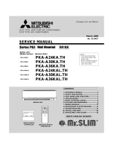
2) Panel heater connector (with a white connector)
This connector is used to perform an interlocked operation with a panel heater. Depending on the indoor unit
control board specification, connect the cable to CN4Y as appropriate
CN4Y for FAN control
(PAC-YU25HT)
<Image>
6-3. PAC-YU25HT (Optional Parts) installation
(3) Locally procured wiring
A basic connection method is shown below.
CN24
X
X
Remote control board Relay circuit Adapter
Indoor unit
control board
Electric Heater
power source
Electric Heater
or panel
heater
Red 1
White 2
Preparations in the field Maximum cable length
is 10 m (32ft)
YellowWhite
White 1
(applicable only when a panel
heater is connected)
3
CN4Y

19
For relay X use the specifications given below Operation coil
Rated voltage: 12VDC
Power consumption: 0.9W or less
* Use the diode that is recommended by the relay manufacturer at both ends of the relay coil.
The length of the electrical wiring for the PAC-YU25HT is 2 meters (6-1/2 ft.)
To extend this length, use sheathed 2-core cable.
Control cable type: CVV, CVS, CPEV or equivalent.
Cable size: 0.5 mm2 ~ 1.25 mm2 (16 to 22 AWG)
Don't extend the cable more than 10 meters (32ft)
(4) Wiring restrictions
Keep the length of the cable connecting to the circuit board of the indoor unit shorter than 10 meters (32ft).
Longer than 10 meters (32ft) could cause improper operation.
Use a transit relay when extending wiring such as remote wiring.
Recommended circuit
Wiring diagram
1-phase
power supply
208V, 230V/60Hz
Control board
FS1, 2 ----- Thermal fuse
H1, H2 ----- Heater
26H --------- Overheat
protection thermostat
88H --------- Electromagnetic contactor
FS1
FS2
FS1
FS2
R
S
R
S
CN24
H2
88H
H1
88H
26H
88H

20
7TROUBLESHOOTING
7-1. CAUTIONS ON TROUBLESHOOTING
(1) Before troubleshooting, check the followings:
1Check the power supply voltage.
2Check the indoor/outdoor connecting wire for mis-wiring.
(2) Take care the followings during servicing.
1Before servicing the air conditioner, be sure to turn off the remote controller first to stop the main unit, and then turn
off the breaker.
2When removing the indoor controller board, hold the edge of the board with care NOT to apply stress on the
components.
3When connecting or disconnecting the connectors, hold the housing of the connector. DO NOT pull the lead wires.
Lead wires
PAR-21MAA
ON/OFF
FILTER
CHECK
OPERATION
CLEAR
TEST
TEMP.
MENU
BACK DAY
MONITOR/SET
CLOCK
ON/OFF
B
C
A
E D F
ERROR CODE
7-2. SELF-CHECK FUNCTION
Wired remote controller
(1) Turn on the power.
(2) Press the [CHECK] button twice.
(3) Set refrigerant address with [TEMP] button
if system control is used.
(4) Press the [ON/OFF] button to stop the
self-check.
A
A
CHECK button
B
B
Indoor Unit’sRefrigerant address
C
C
TEMP button
D
D
IC : Indoor unit
OC : Outdoor unit
E
E
Check code
F
F
Indoor Unit No.
1 Check code Symptom Remark
P1 Intake sensor error
P2 Pipe (TH2) sensor error
P9 Pipe (TH5) sensor error
E6,E7 Indoor/outdoor unit communication error
P4 Drain sensor error
P5 Drain pump error
P6 Freezing/Overheating protection operation
EE Communication error between indoor and outdoor units
P8 Pipe temperature error
E0, E3~E5 Remote controller transmission error
E1, E2 Remote controller control board error
Fb Indoor unit control system error (memory error, etc.)
E9 Indoor/outdoor unit communication error (Transmitting error) (Outdoor unit)
UP Compressor overcurrent interruption
U3,U4 Open/short of outdoor unit thermistors
UF Compressor overcurrent interruption (When compressor locked)
U2 Abnormal high discharging temperature/49C worked/insufficient refrigerant
U1,Ud Abnormal high pressure (63H worked)/Overheating protection operation
U5 Abnormal temperature of heat sink
U8 Outdoor unit fan safeguard stop
U6 Compressor overcurrent interruption/Abnormal of power module
U7 Abnormality of super heat due to low discharge temperature
U9,UH Abnormality such as overvoltage or voltage shortage and abnormal synchronous signal to main circuit
/Current sensor error
Others Other errors (Refer to the technical manual for the outdoor unit.)
For details, check the LED display
of the outdoor controller board.
As for outdoor unit, refer to
service manual OC322.
• On wired remote controller.
1 Check code displayed in the LCD.
• For description of each check code, refer to the following table.
Page is loading ...
Page is loading ...
Page is loading ...
Page is loading ...
Page is loading ...
Page is loading ...
Page is loading ...
Page is loading ...
Page is loading ...
Page is loading ...
Page is loading ...
Page is loading ...
Page is loading ...
Page is loading ...
Page is loading ...
/